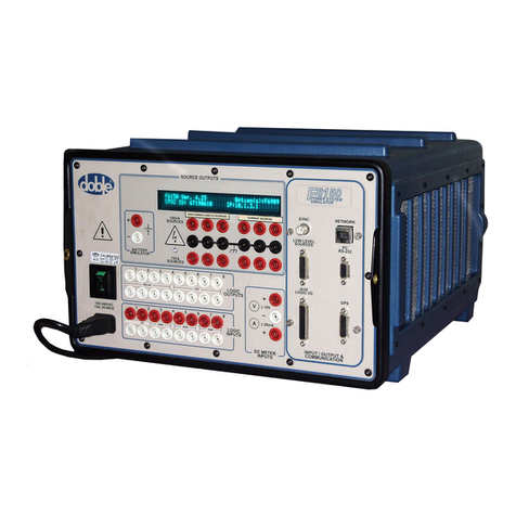
doble F6000 User manual

D
DD
DR
RR
RA
AA
AF
FF
FT
TT
T
2
22
2/
//
/1
11
15
55
5/
//
/0
00
01
11
1
Doble Engineering Company
85 Walnut Street
Watertown, Massachusetts 02472-4037
(USA)
PN 500-0206 72A-1589 Rev. C 02/01
F6000 Family of
Power System Simulators
User Guide

This Manual is solely the property of the Doble Engineering Company
(Doble) and, along with the ProTesT software to which it applies, is
provided for the exclusive use of Doble Clients under contractual
agreement for Doble test equipment and services.
In no event does the Doble Engineering Company assume the liability for
any technical or editorial errors of commission or omission; nor is Doble
liable for direct, indirect, incidental, or consequential damages arising
out of the inability to use this Manual.
Government Restricted Rights Legend: Use, Duplication, or Disclosure
by the US Government is subject to restrictions as set forth in
subparagraphs (c) (1) and (c) (2) of the Commercial Computer Software -
Restricted Rights Clause at FAR 52.227-19.
This manual is protected by copyright, all rights reserved. No part of this
book shall be reproduced, stored in a retrieval system, or transmitted by
any means, electronic, mechanical, photocopying, recording, or
otherwise without written permission from the Doble Engineering
Company.
Doble, the Doble logo, ProTesT, F2000, and F6000 are trademarks of
Doble Engineering Company.
Microsoft, Windows, Windows 95, Windows 98 and Windows NT are
registered trademarks of Microsoft Corporation in the United States
and/or other countries. SQL Anywhere is a registered trademark of
Sybase Corporation.
Copyright 2000-2001.
By Doble Engineering Company
All Rights Reserved

Warranty
Equipment Limited
Warranty
Doble Engineering Company (DOBLE) warrants the products that it manu-
factures to be free from defects in material and workmanship for a period of
one year from the date shipped from the factory.
During the one year warranty period, DOBLE will repair or replace, at its
option, any defective products or components thereof at no additional
charge, provided that the product or component is returned, shipping
prepaid, to DOBLE. The Purchaser is responsible for insuring any product
or component so returned and assumes the risk of loss during shipment.
All replaced products and components become the property of DOBLE.
THIS LIMITED WARRANTY DOES NOT EXTEND TO ANY PRODUCTS
WHICH HAVE BEEN DAMAGED AS A RESULT OF ACCIDENT, MISUSE,
ABUSE, OR AS A RESULT OF MODIFICATION BY ANYONE OTHER
THAN DOBLE OR AN AUTHORIZED DOBLE REPRESENTATIVE.
EXCEPT AS EXPRESSLY SET FORTH ABOVE, NO OTHER WARRANTIES,
EXPRESSED OR IMPLIED, ARE MADE WITH RESPECT TO THE PRODUCT
INCLUDING, BUT NOT LIMITED TO, ANY IMPLIED WARRANTIES OF
MERCHANTABILITY AND FITNESS FOR A PARTICULAR PURPOSE. DOBLE
EXPRESSLY DISCLAIMS ALL WARRANTIES NOT STATED HEREIN. IN THE
EVENT THE PRODUCT IS NOT FREE FROM DEFECTS AS WARRANTED
ABOVE, THE PURCHASER’S SOLE REMEDY SHALL BE REPAIR OR
REPLACEMENT AS PROVIDED ABOVE. UNDER NO CIRCUMSTANCES
WILL DOBLE BE LIABLE TO THE PURCHASER OR ANY USER FOR ANY
DAMAGES, INCLUDING WITHOUT LIMITATION, PERSONAL INJURY OR
PROPERTY DAMAGE CAUSED BY THE PRODUCT, ANY INCIDENTAL OR
CONSEQUENTIAL DAMAGES, EXPENSES, LOST PROFITS, LOST SAVINGS,
OR OTHER DAMAGES ARISING OUT OF THE USE OF OR INABILITY TO
USE THIS PRODUCT.

Software Limited
Warranty
Doble warrants that: (i) for a period of one hundred twenty (120) days
from the date of shipment from Doble, the media on which the Software
is furnished will be free of defects in materials and workmanship under
normal use; and (ii) for a period of one year from the date of shipment
from Doble, the Software will perform in substantial conformance to its
published specifications. This limited warranty extends only to Customer
as the original licensee. Customer’s exclusive remedy and Doble’s entire
liability under this limited warranty will be, at Doble’s option, to repair or
replace the Software, or to refund a pro rata portion of the purchase
price. Doble makes no warranty or representation that its software
products will meet Customer’s requirements, that the operation of the
software products will be uninterrupted or error free, or that all defects in
the software products will be corrected.
This warranty does not apply if the software (a) has been altered, except
by Doble, (b) has not been installed, operated, repaired, or maintained in
accordance with instructions supplied by Doble, (c) has been subjected
to abnormal physical or electrical stress, misuse, negligence, or accident,
or (d) is used in ultrahazardous activities.
Disclaimer THE FOREGOING WARRANTIES AND REMEDIES ARE EXCLUSIVE
AND ARE IN LIEU OF ALL OTHER WARRANTIES, TERMS, OR
CONDITIONS, EXPRESS OR IMPLIED, WHETHER ALLEGED TO ARISE
BY LAW, BY REASON OF CUSTOM OR USAGE IN THE TRADE, OR BY
COURSE OF DEALING, INCLUDING WARRANTIES, TERMS, OR
CONDITIONS OF MERCHANTABILITY, FITNESS FOR A PARTICULAR
PURPOSE, SATISFACTORY QUALITY, CORRESPONDENCE WITH
DESCRIPTION, AND NONINFRINGEMENT, ALL OF WHICH ARE
EXPRESSLY DISCLAIMED.
IN NO EVENT WILL DOBLE BE LIABLE FOR ANY LOST REVENUE,
PROFIT, OR DATA, OR FOR SPECIAL, INDIRECT, CONSEQUENTIAL,
INCIDENTAL, OR PUNITIVE DAMAGES HOWEVER CAUSED AND
REGARDLESS OF THE THEORY OF LIABILITY ARISING OUT OF THE
USE OF OR INABILITY TO USE THE SOFTWARE EVEN IF DOBLE HAS
BEEN ADVISED OF THE POSSIBILITY OF SUCH DAMAGES. In no event
shall Doble’s liability to Customer, whether in contract, tort (including
negligence), or otherwise, exceed the price paid by Customer. The
foregoing limitations shall apply even if the above-stated warranty fails of
its essential purpose. SOME STATES DO NOT ALLOW LIMITATION OR
EXCLUSION OF LIABILITY OR CONSEQUENTIAL OR INCIDENTAL
DAMAGES.

Limitations of
Remedies
DOBLE’s entire liability and Purchaser’s exclusive remedy shall be:
1. The replacement of any disks not meeting DOBLE’S “limited
warranty” which are returned to DOBLE.
2. If DOBLE is unable to deliver replacement disks which are free from
defects in materials and workmanship, Purchaser may terminate this
agreement. By returning the software product and all copies thereof
in any form and affirming compliance with this requirement in
writing, DOBLE will refund the purchase price.
IN NO EVENT WILL DOBLE BE LIABLE TO PURCHASER FOR ANY
DAMAGES, INCLUDING ANY LOST PROFITS, LOST SAVINGS OR
OTHER INCIDENTAL OR CONSEQUENTIAL DAMAGES ARISING OUT
OF THE USE OR INABILITY TO USE SUCH SOFTWARE PRODUCT,
EVEN IF DOBLE OR AN AUTHORIZED DEALER HAS BEEN ADVISED
OF THE POSSIBILITY OF SUCH DAMAGES, OR FOR ANY CLAIM BY
ANY OTHER PARTY.
Some states do not allow the limitation or exclusion of liability for
incidental or consequential damages, so the above limitation or
exclusion may not apply.
For Equipment Maintenance, contact:
Customer Service Manager (Extension 321)
Doble Engineering Company
85 Walnut Street
Watertown, MA 02472-4037 (USA)
Telephone: 617-926-4900
FAX: 617-926-0528
Email: customerservice@doble.com


72A-1589 Rev. C 02/01 i
D
DD
DR
RR
RA
AA
AF
FF
FT
TT
T
3
33
3/
//
/5
55
5/
//
/0
00
01
11
1
Contents
Preface ......................................................................................................... xiii
Structure of This Manual ...................................................................................................... xiii
Document Conventions..........................................................................................................xv
Notes, Cautions, and Warnings .............................................................................................xvi
Safety...................................................................................................................................xvii
1. Introducing the F6150 ...............................................................................1-1
Hardware Architecture.........................................................................................................1-2
ProTesT................................................................................................................................1-3
Control Panel .......................................................................................................................1-5
Options................................................................................................................................1-6
2. Instrument Front Panel ..............................................................................2-1
Source Outputs ....................................................................................................................2-2
Instrument Display..........................................................................................................2-2
Voltage and Current Sources........................................................................................... 2-3
Battery Simulator ............................................................................................................2-6
Auxiliary Functions ..............................................................................................................2-6
Communications ............................................................................................................2-7
Logic Outputs.................................................................................................................2-7
Logic Inputs....................................................................................................................2-8
DC Meter Inputs .............................................................................................................2-8
Power.............................................................................................................................2-8
3. Setup and Configuration ............................................................................3-1
Getting Started .....................................................................................................................3-1
Setup Display.......................................................................................................................3-5
F6000 Instrument Communications ................................................................................ 3-6
F6000 Configuration ............................................................................................................ 3-7
Pre-set Configurations...................................................................................................3-10
F6000 Control Panel .......................................................................................................... 3-11

ii 72A-1589 Rev. C 02/01
D
DD
DR
RR
RA
AA
AF
FF
FT
TT
T
3
33
3/
//
/5
55
5/
//
/0
00
01
11
1
4. Control Panel Operations ......................................................................... 4-1
Source Table........................................................................................................................ 4-2
Ramp/Set Sources ................................................................................................................4-6
Sources to Change.......................................................................................................... 4-6
Variable to Change......................................................................................................... 4-7
Control Arrows............................................................................................................... 4-7
Mode and Ramp/Delta Step............................................................................................ 4-8
Store and Recall ............................................................................................................. 4-8
Phasor Diagram ................................................................................................................... 4-8
Range Settings................................................................................................................ 4-9
Fault Rotate.................................................................................................................. 4-10
Multiple Phasors........................................................................................................... 4-11
Logic and Timer Settings.................................................................................................... 4-13
Inputs Tab .................................................................................................................... 4-13
Outputs Tab ................................................................................................................. 4-15
Timers Tab ................................................................................................................... 4-16
Notes Tab..................................................................................................................... 4-23
Timers................................................................................................................................ 4-24
Timing Status................................................................................................................ 4-25
Timer Controls ............................................................................................................. 4-25
Measurement Units ...................................................................................................... 4-25
Input and Output Indicators............................................................................................... 4-26
Battery Simulator ...............................................................................................................4-28
Saving the F6000 Control Panel Configuration................................................................... 4-29
Summary ........................................................................................................................... 4-29

F6000 Family of Power System Simulators User Guide
72A-1589 Rev. C 02/01 iii
D
DD
DR
RR
RA
AA
AF
FF
FT
TT
T
3
33
3/
//
/5
55
5/
//
/0
00
01
11
1
5. Basic Test Procedures ................................................................................5-1
Prepare for a Pickup Test......................................................................................................5-1
Control Panel Operations.....................................................................................................5-3
Source Table ..................................................................................................................5-4
Settings Display..............................................................................................................5-5
Ramp/Set Sources ...........................................................................................................5-6
Conduct the Test ............................................................................................................ 5-7
Time Test .............................................................................................................................5-8
Fault Rotate........................................................................................................................5-17
Reach Test..........................................................................................................................5-21
Source Table ................................................................................................................5-22
Settings Display............................................................................................................5-24
Ramp/Set Sources .........................................................................................................5-25
Conduct the Test .......................................................................................................... 5-26
6. Troubleshooting Guide ..............................................................................6-1
Troubleshooting Flow Charts................................................................................................6-1
General Troubleshooting Techniques...................................................................................6-4
LED Status Indicators............................................................................................................6-5
Amplifier Circuit Boards .................................................................................................6-5
CPU Circuit Board..........................................................................................................6-6
Analog I/O Circuit Board................................................................................................6-7
Power Supply Circuit Board............................................................................................6-8
Component Checkout Procedures ........................................................................................ 6-9
Power Supply Checks ..................................................................................................... 6-9
Logic I/O Printed Circuit Board Checks...........................................................................6-9
Voltage or Current Amplifier Board Checks ..................................................................6-10
Battery Simulator Checks..............................................................................................6-10
Cooling Fan Checks......................................................................................................6-10
Resolving Communications Problems.................................................................................6-11
Error Types.........................................................................................................................6-11
Hardware Errors............................................................................................................6-11
Source Errors ................................................................................................................6-14
System Errors ................................................................................................................6-16

iv 72A-1589 Rev. C 02/01
D
DD
DR
RR
RA
AA
AF
FF
FT
TT
T
3
33
3/
//
/5
55
5/
//
/0
00
01
11
1
7. Field Replacement Procedures .................................................................. 7-1
Preparatory Steps ................................................................................................................. 7-1
Remove the Instrument Cover ........................................................................................ 7-2
Power Up and Perform a Visual Check........................................................................... 7-5
Instrument Front Panel......................................................................................................... 7-5
Communications Board ..................................................................................................... 7-13
Circuit Board Replacement ................................................................................................ 7-17
Battery Simulator ...............................................................................................................7-19
Cooling Fans...................................................................................................................... 7-22
Verify the Replacement...................................................................................................... 7-26
Replaceable Components and Cables ................................................................................ 7-26
8. Safety and Maintenance ............................................................................ 8-1
F6150 Rules for Safe Operation ........................................................................................... 8-1
Cleaning the F6150..............................................................................................................8-2
Customer Service ........................................................................................................... 8-2
Safe Packing of the F6150.................................................................................................... 8-3
Appendix A. Software Maintenance ..............................................................A-1
Flash Loader ........................................................................................................................A-1
Loading New Firmware..................................................................................................A-2
Communications Parameters..........................................................................................A-3
Key Code Update.................................................................................................................A-5
Appendix B. Ethernet Communications .........................................................B-1
Connect the Control PC to the F6150................................................................................... B-2
Configure the Control PC..................................................................................................... B-3
Set the F6000 IP Address...................................................................................................... B-8
Appendix C. Source Configurations ..............................................................C-1
Convertible Voltage/Current Sources....................................................................................C-1
Current Sources ...................................................................................................................C-1
Rules for Source Selection....................................................................................................C-2
Compliance Voltage and Current Range ..............................................................................C-3
Pre-set Configurations..........................................................................................................C-5

F6000 Family of Power System Simulators User Guide
72A-1589 Rev. C 02/01 v
D
DD
DR
RR
RA
AA
AF
FF
FT
TT
T
3
33
3/
//
/5
55
5/
//
/0
00
01
11
1
Appendix D. Global Positioning System .......................................................D-1
GPS Synchronization........................................................................................................... D-1
Equipment Setup .................................................................................................................D-3
Conduct the Test ................................................................................................................. D-4
Appendix E. Timing Between State Changes ..................................................E-1
Appendix F. Field Calibration Verification ....................................................F-1
Testing Specifications........................................................................................................... F-1
Ambient Accuracy.......................................................................................................... F-1
Test Setup....................................................................................................................... F-1
Test Equipment............................................................................................................... F-1
Amplitude and Distortion Checks......................................................................................... F-2
75 VA High Current Source ............................................................................................ F-2
150 VA High Current Source.......................................................................................... F-4
300 VA High Current Source.......................................................................................... F-5
450 VA High Current Source.......................................................................................... F-6
75 VA Convertible Low Current Source .......................................................................... F-8
150 VA Convertible Low Current Source........................................................................ F-9
300 VA Convertible Low Current Source...................................................................... F-10
450 VA Convertible Low Current Source...................................................................... F-12
75 VA Convertible Voltage Source................................................................................ F-13
150 VA Convertible Voltage Source.............................................................................. F-14
Phase Shift Testing.............................................................................................................. F-16
75 VA (Right Bank) High Current Sources at 50 or 60 Hz ............................................. F-16
75 VA Convertible Voltage Sources at 50 or 60 Hz....................................................... F-17

vi 72A-1589 Rev. C 02/01
D
DD
DR
RR
RA
AA
AF
FF
FT
TT
T
3
33
3/
//
/5
55
5/
//
/0
00
01
11
1
Appendix G. F6150 Specifications ............................................................... G-1
Convertible Voltage/Current Sources....................................................................................G-1
Source Configurations ....................................................................................................G-1
Ranges and Resolution ...................................................................................................G-1
Current Sources ...................................................................................................................G-3
Source Configurations ....................................................................................................G-3
Ranges and Resolution ...................................................................................................G-3
Battery Simulator .................................................................................................................G-4
General Specifications .........................................................................................................G-5
Source Operation...........................................................................................................G-5
Electrostatic Discharge Immunity ...................................................................................G-5
Surge Withstand Capability ............................................................................................G-5
AC Amplitude Accuracy at 50/60 Hz .............................................................................G-5
Distortion.......................................................................................................................G-5
Noise (10-30 kHz)..........................................................................................................G-5
Phase Angle ...................................................................................................................G-6
Frequency ......................................................................................................................G-6
Ramp/Set........................................................................................................................G-6
Logic Outputs.................................................................................................................G-6
Logic Inputs....................................................................................................................G-7
Triggers ..........................................................................................................................G-7
Timers............................................................................................................................G-7
Input Power Supply........................................................................................................G-7
Temperature...................................................................................................................G-7
Humidity........................................................................................................................G-7
Interfaces........................................................................................................................G-7
Safety.............................................................................................................................G-8
Electromagnetic Compatibility (EMC) .............................................................................G-8
Enclosure .......................................................................................................................G-8
Measurements................................................................................................................G-8
Index .............................................................................................................I-1

72A-1589 Rev. C 02/01 vii
D
DD
DR
RR
RA
AA
AF
FF
FT
TT
T
3
33
3/
//
/5
55
5/
//
/0
00
01
11
1
Figures
Figure 1.1 F6000 Power System Simulator ........................................................................ 1-1
Figure 1.2 Instrument Architecture ...................................................................................1-2
Figure 1.3 Test Setup with ProTesT, F6000 Instrument, and Relay Under Test .................. 1-4
Figure 1.4 F6000 Control Panel ........................................................................................ 1-5
Figure 2.1 F6000 Instrument Front Panel .......................................................................... 2-1
Figure 2.2 F6000 Instrument Front Panel Source Outputs .................................................2-3
Figure 2.3 Six 150 VA Sources .........................................................................................2-4
Figure 2.4 Four 150 VA Sources and Four 75 VA Sources ................................................ 2-5
Figure 2.5 Six 75 VA Sources ...........................................................................................2-6
Figure 3.1 Instrument Display After Successful Bootup......................................................3-2
Figure 3.2 Login Display ...................................................................................................3-4
Figure 3.3 Setup Display ..................................................................................................3-5
Figure 3.4 Configuration Display.......................................................................................3-7
Figure 3.5 Configuration Display with Source Summary ...................................................3-8
Figure 3.6 F6000 Control Panel ......................................................................................3-11
Figure 4.1 F6000 Control Panel ........................................................................................ 4-1
Figure 4.2 Source Table ....................................................................................................4-3
Figure 4.3 Ramp/Set Sources Section.................................................................................4-6
Figure 4.4 Phasor Diagram................................................................................................4-9
Figure 4.5 Phasors for Three Voltage Sources Separated 120° ........................................4-11
Figure 4.6 Dotted Lines Show New Position of Phasors Before Release ..........................4-12
Figure 4.7 Phasors for Three Voltage Sources Shifted ~45° ............................................. 4-12
Figure 4.8 Inputs Tab .....................................................................................................4-13
Figure 4.9 Outputs Tab ..................................................................................................4-15
Figure 4.10 Timers Tab ....................................................................................................4-16
Figure 4.11 Triggers Display..............................................................................................4-17
Figure 4.12 Set Trigger Logic.............................................................................................4-18
Figure 4.13 Trigger Logic Set for Trigger 1.........................................................................4-20
Figure 4.14 Start and Stop Conditions Set in the Timers Tab .............................................4-22
Figure 4.15 Notes Tab ......................................................................................................4-23
Figure 4.16 Timers Section................................................................................................4-24
Figure 4.17 Output and Input Status Indicators.................................................................. 4-26
Figure 4.18 Input and Output Indicators for Four Voltage Sources and
Four Current Sources......................................................................................4-26

Figures
viii 72A-1589 Rev. C 02/01
D
DD
DR
RR
RA
AA
AF
FF
FT
TT
T
3
33
3/
//
/5
55
5/
//
/0
00
01
11
1
Figure 4.19 Input and Output Indicators for Three Voltage Sources
and Three Current Sources............................................................................. 4-27
Figure 4.20 Input and Output Indicators for Six Current Sources....................................... 4-27
Figure 4.21 Battery Section............................................................................................... 4-28
Figure 5.1 Configuration Display ...................................................................................... 5-2
Figure 5.2 F6000 Control Panel ....................................................................................... 5-3
Figure 5.3 Source Table Settings for the Pickup Test ........................................................ 5-4
Figure 5.4 Inputs Tab of the Settings Display .................................................................... 5-5
Figure 5.5 Settings in the Ramp/Set Sources Section ......................................................... 5-6
Figure 5.6 Source Table Settings for Time Test ................................................................. 5-8
Figure 5.7 Inputs Tab ....................................................................................................... 5-9
Figure 5.8 Timers Tab .................................................................................................... 5-10
Figure 5.9 Triggers Display ............................................................................................. 5-11
Figure 5.10 Set Trigger Logic ............................................................................................ 5-12
Figure 5.11 Trigger Logic Set for Input 1 ........................................................................... 5-12
Figure 5.12 Verify Trigger Logic........................................................................................ 5-13
Figure 5.13 Start and Stop Condition Definitions for Timer 1 ........................................... 5-14
Figure 5.14 Timer 1 Enabled on the Control Panel ........................................................... 5-15
Figure 5.15 Initial Setup for the Fault Rotate Test ............................................................. 5-18
Figure 5.16 Fault Rotated to I2 ......................................................................................... 5-19
Figure 5.17 Fault Rotated to I3 ......................................................................................... 5-20
Figure 5.18 Configuration Display .................................................................................... 5-21
Figure 5.19 Source Table Settings for the Reach Test ....................................................... 5-23
Figure 5.20 Inputs Tab of the Settings Display .................................................................. 5-24
Figure 5.21 Settings in the Ramp/Set Sources Section........................................................ 5-25
Figure 5.22 Control Panel Settings for the Reach Test ...................................................... 5-26
Figure 6.1 Troubleshooting Flow Chart — Part 1 ............................................................. 6-2
Figure 6.2 Troubleshooting Flow Chart — Part 2 ............................................................. 6-3
Figure 6.3 CPU Board Status Indicator LEDs and Push Button .......................................... 6-6
Figure 6.4 System Error Message .................................................................................... 6-16
Figure 6.5 System Error Diagnostic Information ............................................................. 6-16
Figure 7.1 Top View of the F6150 Instrument .................................................................. 7-2
Figure 7.2 Rubber Feet at the Back of the Instrument ........................................................ 7-3
Figure 7.3 Instrument Rear with Cover Removed .............................................................. 7-4
Figure 7.4 Instrument Front Panel Tilted Forward 30° ....................................................... 7-6
Figure 7.5 Front Panel Lying Face Down in Front of the Instrument ................................. 7-7
Figure 7.6 Instrument Front Panel with Wires Disconnected ............................................ 7-8
Figure 7.7 Wire Connections at the Front Panel Circuit Breaker ....................................... 7-9

F6000 Family of Power System Simulators User Guide
72A-1589 Rev. C 02/01 ix
D
DD
DR
RR
RA
AA
AF
FF
FT
TT
T
3
33
3/
//
/5
55
5/
//
/0
00
01
11
1
Figure 7.8 Circuit Breaker with Wires Disconnected ......................................................7-10
Figure 7.9 Communications Board Ready for Removal ...................................................7-14
Figure 7.10 Right Side of the Instrument Front Panel .........................................................7-15
Figure 7.11 Battery Simulator Mounted at the Back of the Instrument................................7-19
Figure 7.12 Removal of the Power Supply and Voltage Amplifiers
for Access to the Battery Simulator ................................................................7-20
Figure 7.13 Back Panel After Removal of Battery Simulator...............................................7-21
Figure 7.14 Side View of the Instrument Before Removal of Cooling Fans ........................7-22
Figure 7.15 Retaining Bracket for Cooling Fans ................................................................7-23
Figure 7.16 Cooling Fans with Wires Connected ..............................................................7-24
Figure 7.17 Cooling Fan Assembly ...................................................................................7-25
Figure A.1 Flash Loader ....................................................................................................A-1
Figure A.2 Set Communications Parameters ......................................................................A-3
Figure A.3 Save Communications Settings ........................................................................A-4
Figure A.4 Key Code Update ............................................................................................A-5
Figure B.1 Alternate 50 Ohm Terminator Connections for the Coax Cable .......................B-2
Figure B.2 Network Display: Scroll to the TCP/IP Network Component ............................B-3
Figure B.3 TCP/IP Properties .............................................................................................B-4
Figure B.4 IP Address Tab in TCP/IP Properties .................................................................B-5
Figure B.5 Successful Ping ................................................................................................B-6
Figure B.6 Unsuccessful Ping ...........................................................................................B-6
Figure B.7 Setup Display Configured for Ethernet Communications ..................................B-7
Figure B.8 Set F6000 IP Address .......................................................................................B-8
Figure C.1 3 Voltages and 3 Currents ................................................................................C-6
Figure C.2 3 Voltages and 3 Transient Currents ................................................................C-6
Figure C.3 4 Voltages and 4 Currents ................................................................................C-7
Figure C.4 6 Currents (right bank) .....................................................................................C-7
Figure C.5 1 Voltage and 2 Low Range Currents ...............................................................C-8
Figure C.6 1 Voltage 150 VA and 1 Current 450 VA .........................................................C-8
Figure C.7 4 Voltages and 4 Transient Currents ................................................................C-9
Figure C.8 6 Voltages .......................................................................................................C-9
Figure C.9 6 Low Range Currents ...................................................................................C-10
Figure C.10 6 Low Range Transients .................................................................................C-10
Figure C.11 6 Transient Currents ......................................................................................C-11
Figure C.12 1 Voltage and 2 Low Range Transients ..........................................................C-11
Figure D.2 Equipment Setup for GPS Synchronization ..................................................... D-4
Figure F.1 75 VA High Current Source Measurement ....................................................... F-3
Figure F.2 150 VA High Current Source Measurement ..................................................... F-5
Figure F.3 300 VA High Current Source Measurement ..................................................... F-6

x72A-1589 Rev. C 02/01
D
DD
DR
RR
RA
AA
AF
FF
FT
TT
T
3
33
3/
//
/5
55
5/
//
/0
00
01
11
1
Figure F.4 450 VA High Current Source Measurement ......................................................F-7
Figure F.5 75 VA Convertible Low Current Source Measurement ......................................F-8
Figure F.6 150 VA Convertible Low Current Source Measurement ..................................F-10
Figure F.7 300 VA Convertible Low Current Source Measurement ..................................F-11
Figure F.8 450 VA Convertible Low Current Source Measurement ..................................F-13
Figure F.9 75 VA Convertible Voltage Source Measurement ...........................................F-14
Figure F.10 150 VA Convertible Voltage Source Measurement .........................................F-15
Figure F.11 Test Setup for Phase Testing Six Current Sources ............................................F-16
Figure F.12 Test Setup for Phase Testing Six Voltage Sources ............................................F-17

72A-1589 Rev. C 02/01 xi
D
DD
DR
RR
RA
AA
AF
FF
FT
TT
T
3
33
3/
//
/5
55
5/
//
/0
00
01
11
1
Tables
Table 2.1 150 VA Convertible Sources Configured to
Supply Low Current at a High Compliance Voltage .......................................... 2-4
Table 2.2 Requirements for Serial and Ethernet Connections............................................2-7
Table 4.1 Indications for Activated Sources......................................................................4-5
Table 4.2 Rotation of a Phase-to-Ground Fault...............................................................4-10
Table 4.3 Sense Conditions for Input Types....................................................................4-14
Table 6.1 Voltage/Current Amplifier Board LED Indicators............................................... 6-5
Table 6.2 CPU Board LED Indicators................................................................................6-6
Table 6.3 Analog I/O Board LED Indicators......................................................................6-7
Table 6.4 Power Supply Board LED Indicators .................................................................6-8
Table 6.5 Hardware Errors .............................................................................................6-12
Table 6.6 Common Source Errors...................................................................................6-15
Table 6.7 System Errors..................................................................................................6-17
Table 7.1 Status Indicator Lights on the Amplifier Boards.................................................7-5
Table 7.2 Wire Connections...........................................................................................7-12
Table 7.3 Circuit Boards in the F6150............................................................................7-17
Table 7.4 Field Replaceable Parts...................................................................................7-26
Table 7.5 Cable and Adapter Replacement List ..............................................................7-27
Table C.1 Maximum Compliance Voltage for Low Current Source Combinations.............C-3
Table C.2 Maximum Compliance Voltage for Low Transient Current
Source Combinations .......................................................................................C-4
Table C.3 Maximum Compliance Voltage for Current Source Combinations ....................C-4
Table C.4 Maximum Compliance Voltage for Transient Current Source Combinations .....C-5
Table F.1 Test Equipment................................................................................................. F-2
Table F.2 75 VA High Current Source Specification......................................................... F-3
Table F.3 150 VA High Current Source Specification....................................................... F-4
Table F.4 300 VA High Current Source Specification....................................................... F-6
Table F.5 450 VA High Current Source Specification....................................................... F-7
Table F.6 75 VA Convertible Low Current Source Specification....................................... F-8
Table F.7 150 VA Convertible Low Current Specification............................................... F-10
Table F.8 300 VA Convertible Low Current Source Specification................................... F-11
Table F.9 450 VA Convertible Low Current Source Specification................................... F-13
Table F.10 75 VA Convertible Voltage Source Specifications ........................................... F-14
Table F.11 150 VA Convertible Voltage Source Specification .......................................... F-15

xii 72A-1589 Rev. C 02/01
D
DD
DR
RR
RA
AA
AF
FF
FT
TT
T
3
33
3/
//
/5
55
5/
//
/0
00
01
11
1

72A-1589 Rev. C 02/01 xiii
D
DD
DR
RR
RA
AA
AF
FF
FT
TT
T
2
22
2/
//
/2
22
20
00
0/
//
/0
00
01
11
1
Preface
The F6000 family of power system simulators consists of an integrated
group of precision test instruments, related options, and associated
control software. The F6000 Family of Power System Simulators User
Guide contains detailed information regarding the setup, operation and
maintenance of the F6000. The sections below explain how the book is
organized and the conventions it uses.
Structure of This Manual
This user guide consists of eight chapters and seven appendices:
Chapter 1 ”Introducing the F6150”
Chapter 1 gives an overview of the F6000
Instrument. Included is a description of the
instrument’s hardware architecture, ProTesT
software, and the options available for the F6000.
Chapter 2 ”Instrument Front Panel”
Chapter 2 explains the features and functions on
the front panel of the F6000 Instrument.
Chapter 3 ”Setup and Configuration”
Chapter 3 shows how to get started with the F6000.
It explains how to configure the software and set
up the instrument.
Chapter 4 ”Control Panel Operations”
Chapter 4 describes the settings and controls on
the F6000 Control Panel and associated displays.
Chapter 5 ”Basic Test Procedures”
Chapter 5 explains how to use the F6000
Instrument to conduct simple tests, and how to
make use of the various features on the Control
Panel.
Chapter 6 ”Troubleshooting Guide”
Chapter 6 provides a diagnostic flow chart for
identifying problems, defines LED status indicators
and lists hardware and software error messages.

Preface
D
DD
DR
RR
RA
AA
AF
FF
FT
TT
T
2
22
2/
//
/2
22
20
00
0/
//
/0
00
01
11
1
xiv 72A-1589 Rev. C 02/01
Chapter 7 ”Field Replacement Procedures”
Chapter 7 gives detailed instructions about how
to remove the various circuit boards in the
instrument, and how to replace them with new
boards.
Chapter 8 ”Safety and Maintenance”
Chapter 8 lists rules for safe use of the F6000
Instrument, discusses routine maintenance of the
equipment, and explains how to obtain service for
the instrument from Doble Engineering.
Appendix A ”Software Maintenance”
Appendix A explains how to use the Flash Loader
to update the F6000 firmware, and how to enable
pre-installed options.
Appendix B ”Ethernet Communications”
Appendix B explains how to assign the control PC
an IP address for the purpose of communicating on
a private internet, and how to change the IP
address of the F6000 Instrument.
Appendix C ”Source Configurations”
Appendix C discusses the different kinds of sources
available on the instrument front panel, gives rules
for source selection, and illustrates the pre-set
source configurations available.
Appendix D ”Global Positioning System”
Appendix D explains how to conduct an
end-to-end test with two F6000 Instruments
synchronized using the Global Positioning System.
Appendix E ”Timing Between State Changes”
Appendix E contains technical information on the
operating characteristics of the F6000 Instrument.
Appendix F ”Field Calibration Verification”
Appendix F lists testing specifications and
procedures for performing amplitude and distortion
tests and phase shift tests on configured current
and voltage sources.
Other manuals for F6000
1
This manual suits for next models
1
Table of contents
Other doble Power Supply manuals