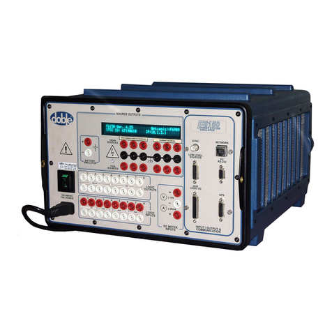
doble F6300 User manual

Doble Engineering Company
85 Walnut Street
Watertown, Massachusetts 02472-4037
(USA)
PN 500-0462 72A-2337-01 Rev. B 11/05
F6300 Power
System Simulator
User Guide

This Manual is solely the property of the Doble Engineering Company (Doble) and,
along with the ProTesT software to which it applies, is provided for the exclusive
use of Doble Clients under contractual agreement for Doble test equipment and
services.
In no event does the Doble Engineering Company assume the liability for any
technical or editorial errors of commission or omission; nor is Doble liable for
direct, indirect, incidental, or consequential damages arising out of the inability to
use this Manual.
Government Restricted Rights Legend: Use, Duplication, or Disclosure by the US
Government is subject to restrictions as set forth in subparagraphs (c) (1) and (c) (2)
of the Commercial Computer Software - Restricted Rights Clause at FAR 52.227-19.
This manual is protected by copyright, all rights reserved. No part of this book shall
be reproduced, stored in a retrieval system, or transmitted by any means, electronic,
mechanical, photocopying, recording, or otherwise without written permission from
the Doble Engineering Company.
Microsoft, Windows, Windows 95, Windows 98, Windows 2000, Windows NT, and
Windows XP are registered trademarks of Microsoft Corporation in the United States
and/or other countries.
Copyright © 2005
By Doble Engineering Company
All Rights Reserved

Warranty
Software Limited Warranty
Doble warrants that: (i) for a period of one year from the date of shipment from Doble, the media
on which the Software is furnished will be free of defects in materials and workmanship under
normal use; and (ii) for a period of one year from the date of shipment from Doble, the Software
will perform in substantial conformance to its published specifications. This limited warranty
extends only to Customer as the original licensee. Customer’s exclusive remedy and Doble’s
entire liability under this limited warranty will be, at Doble’s option, to repair or replace the
Software, or to refund a pro rata portion of the purchase price. Doble makes no warranty or
representation that its software products will meet Customer’s requirements, that the operation of
the software products will be uninterrupted or error free, or that all defects in the software
products will be corrected.
This warranty does not apply if the software (a) has been altered, except by Doble, (b) has not
been installed, operated, repaired, or maintained in accordance with instructions supplied by
Doble, (c) has been subjected to abnormal physical or electrical stress, misuse, negligence, or
accident, or (d) is used in ultrahazardous activities.
Disclaimer
THE FOREGOING WARRANTIES AND REMEDIES ARE EXCLUSIVE AND ARE IN LIEU OF ALL
OTHER WARRANTIES, TERMS, OR CONDITIONS, EXPRESS OR IMPLIED, WHETHER
ALLEGED TO ARISE BY LAW, BY REASON OF CUSTOM OR USAGE IN THE TRADE, OR BY
COURSE OF DEALING, INCLUDING WARRANTIES, TERMS, OR CONDITIONS OF
MERCHANTABILITY, FITNESS FOR A PARTICULAR PURPOSE, SATISFACTORY QUALITY,
CORRESPONDENCE WITH DESCRIPTION, AND NONINFRINGEMENT, ALL OF WHICH ARE
EXPRESSLY DISCLAIMED.
IN NO EVENT WILL DOBLE BE LIABLE FOR ANY LOST REVENUE, PROFIT, OR DATA, OR FOR
SPECIAL, INDIRECT, CONSEQUENTIAL, INCIDENTAL, OR PUNITIVE DAMAGES HOWEVER
CAUSED AND REGARDLESS OF THE THEORY OF LIABILITY ARISING OUT OF THE USE OF
OR INABILITY TO USE THE SOFTWARE EVEN IF DOBLE HAS BEEN ADVISED OF THE
POSSIBILITY OF SUCH DAMAGES. In no event shall Doble’s liability to Customer, whether in
contract, tort (including negligence), or otherwise, exceed the price paid by Customer. The
foregoing limitations shall apply even if the above-stated warranty fails of its essential purpose.
SOME STATES DO NOT ALLOW LIMITATION OR EXCLUSION OF LIABILITY OR
CONSEQUENTIAL OR INCIDENTAL DAMAGES.

Limitations of Remedies
DOBLE’s entire liability and Purchaser’s exclusive remedy shall be:
• The replacement of any disks not meeting DOBLE’S “limited warranty” that are returned
to DOBLE.
• If DOBLE is unable to deliver replacement disks that are free from defects in materials
and workmanship, Purchaser may terminate this agreement. By returning the software
product and all copies thereof in any form and affirming compliance with this
requirement in writing, DOBLE will refund the purchase price.
IN NO EVENT WILL DOBLE BE LIABLE TO PURCHASER FOR ANY DAMAGES, INCLUDING
ANY LOST PROFITS, LOST SAVINGS OR OTHER INCIDENTAL OR CONSEQUENTIAL
DAMAGES ARISING OUT OF THE USE OR INABILITY TO USE SUCH SOFTWARE PRODUCT,
EVEN IF DOBLE OR AN AUTHORIZED DEALER HAS BEEN ADVISED OF THE POSSIBILITY OF
SUCH DAMAGES, OR FOR ANY CLAIM BY ANY OTHER PARTY.
Some states do not allow the limitation or exclusion of liability for incidental or consequential
damages, so the above limitation or exclusion may not apply.
For Equipment Maintenance, contact:
Customer Service Manager 1-617-293-2921
Doble Engineering Company
85 Walnut Street
Watertown, MA 02472-4037 (USA)
Telephone: 617-926-4900
FAX: 617-926-0528
Email: customerservice@doble.com

F6300 Power System Simulator User Guide
72A-2337-01 Rev. B 11/05 i
Contents
1. Introducing the F6300 ...............................................................................1-1
Hardware Architecture............................................................................................................................... 1-2
Control Panel Version 2 ............................................................................................................................. 1-3
What is ProTesTTM.................................................................................................................................... 1-4
2. F6300 Front Panel .....................................................................................2-1
Source Outputs .......................................................................................................................................... 2-1
Instrument Display ..................................................................................................................................... 2-2
Current Sources.......................................................................................................................................... 2-2
Auxiliary Functions .................................................................................................................................... 2-3
Communications ................................................................................................................................. 2-3
Connecting the F6300 and F6150 .............................................................................................................. 2-3
Ethernet 10Base 2 Communications with a “T” Connector .................................................................. 2-3
Ethernet 10Base 2 Communication using Terminators ......................................................................... 2-5
Ethernet Communication to F6000 Instruments ................................................................................... 2-5
Serial Communication to F6000 Instruments ..................................................................................... 2-10
Low Level Source Connections ................................................................................................................ 2-13
Power ...................................................................................................................................................... 2-14
3. Setup and Configuration ............................................................................3-1
Getting Started ........................................................................................................................................... 3-1
Using the Setup Preferences ....................................................................................................................... 3-3
Using the F6300 Configuration Window .................................................................................................... 3-3
4. Troubleshooting the F6300 ........................................................................4-1
Troubleshooting Flow Charts...................................................................................................................... 4-1
General Troubleshooting Techniques......................................................................................................... 4-4
LED Status Indicators.................................................................................................................................. 4-4
Current Amplifier Circuit Boards.......................................................................................................... 4-5
CPU1 and CPU2 Circuit Boards .......................................................................................................... 4-6
Analog Multiplexer Circuit Board ........................................................................................................ 4-8
High Voltage Power Supply Circuit Board ........................................................................................... 4-9
Component Checkout Procedures ............................................................................................................ 4-10
Checking the Power Supply............................................................................................................... 4-10

ii 72A-2337-01 Rev. B 11/05
Checking the Current Amplifier Board................................................................................................4-10
Checking the Cooling Fans.................................................................................................................4-10
Resolving Communications Problems.......................................................................................................4-11
Error Types ...............................................................................................................................................4-11
Hardware Errors .................................................................................................................................4-11
Source Errors......................................................................................................................................4-13
System Errors......................................................................................................................................4-14
5. Field Replacement Procedures .................................................................. 5-1
Preparatory Steps........................................................................................................................................5-1
Remove the Instrument Cover ..............................................................................................................5-2
Perform a Power Up and a Visual Check to Identify a Faulty Component.............................................5-4
Remove and Replace the Instrument Front Panel ........................................................................................5-4
Removing and Replacing the Communications Board ................................................................................5-8
Removing and Replacing Circuit Boards.....................................................................................................5-9
Removing and Replacing the Cooling Fans...............................................................................................5-10
Verify the Replacement ............................................................................................................................5-12
Replaceable Components and Cables.......................................................................................................5-13
6. Safety and Maintenance ............................................................................ 6-1
F6300 Rules for Safe Operation ..................................................................................................................6-1
Cleaning the F6300 ....................................................................................................................................6-1
Customer Service .................................................................................................................................6-2
Returning the F6300 ...................................................................................................................................6-2
Appendix A. Firmware Maintenance .............................................................A-1
Flash Loader .............................................................................................................................................. A-1
About F6XXX Firmware....................................................................................................................... A-2
Communications Parameters............................................................................................................... A-3
Appendix B. Configuring Windows for
Ethernet Communications ..........................................................B-1
Configuring the Control PC........................................................................................................................ B-1
Setting the F6300 IP Address ..................................................................................................................... B-4
Appendix C. Source Configurations ..............................................................C-1
Current Sources ......................................................................................................................................... C-1
Rules for Source Selection ......................................................................................................................... C-1
Compliance Voltage and Current Range .................................................................................................... C-1

F6300 Power System Simulator User Guide
72A-2337-01 Rev. B 11/05 iii
User Defined Configurations ......................................................................................................................C-3
Appendix D. Field Calibration Verification ..................................................D-1
Testing Specifications................................................................................................................................ D-1
Ambient Accuracy.............................................................................................................................. D-1
Test Setup........................................................................................................................................... D-1
Test Equipment................................................................................................................................... D-1
Testing a 150 VA High Current Source ............................................................................................... D-2
Testing a 450 VA High Current Source ............................................................................................... D-3
Phase Shift Testing .................................................................................................................................... D-5
Appendix E. F6300 Specifications ..................................................................E-1
Current Sources.......................................................................................................................................... E-1
Ranges and Resolution ............................................................................................................................... E-1
General Specifications ............................................................................................................................... E-2

iv 72A-2337-01 Rev. B 11/05

72A-2337-01 Rev. B 11/05 1-1
1. Introducing the F6300
The 6300 High Power Current Module (Figure 1.1), used in conjunction with the F6150 Power
System Simulator, provides you with realistic power system simulation for protection schemes.
The F6300 has two groups of three current sources, six in total. Each source is rated at 150 VA of
continuous power or 225 VA of power for 1.5 seconds. Also, each group can be configured as
one source at 450 VA of continuous power or 675 VA of power for 1.5 seconds. The F6300
provides:
• Six 150 VA current sources
or
• Two 450 VA current sources
Figure 1.1 F6300
Configuration of the sources is internal and independently controlled by a computer to meet
diverse requirements for various relay tests. By configuring the current sources in series or in
parallel, the F6300 yields more power for testing high burden relays or protection schemes.

Hardware Architecture
1-2 72A-2337-01 Rev. B 11/05
Hardware Architecture
The F6300 High Power Current Amplifier (Figure 1.2) is designed to work in conjunction with
the F6150 Power System Simulator. The F6150 is responsible for the waveform generation. The
F6300 makes the control of the amplifiers available to the F6150 via the Ethernet link and the
low level input connection.
The components of the F6300 Instrument are:
• Front Panel
• CPU Board
• Analog Multiplexer board
• Six Current Amplifiers
• Power Supply
• Four Cooling Fans
Power Supply
Current Source
Current Source
Current Source
Current Source
Current Source
Analog Multiplexer
CPU
Comm.
Output Terminal Board & Display
Current Source
Fans
Figure 1.2 F6300 Components

F6300 Power System Simulator User Guide
72A-2337-01 Rev. B 11/05 1-3
Control Panel Version 2
The F6000 Control Panel Version 2 (Figure 1.3) controls the power system simulator from a
computer connected to the instrument’s front panel. It configures and controls the instrument’s
voltage sources, current sources, logic inputs, logic outputs, and timers. The F6000 Control Panel
Version 2 emulates front panel controls. It also employs flexible data entry procedures to
accommodate the wide range of test configurations possible. The Control Panel’s (Version 2)
intuitive controls can check a relay without an elaborate test plan.
A stand alone version of the Control Panel (Version 2) is shipped with each F6000 instrument.
Figure 1.3 F6000 Control Panel Version 2

What is ProTesTTM
1-4 72A-2337-01 Rev. B 11/05
What is ProTesTTM
ProTesT is a software system for protective relay testing and equipment maintenance. It includes
the F6000 Control Panel (Version 2) for manual control of the instrument. It also combines
automatic control of the F6300 instrument with the functions of a client server database.
ProTesT uses test templates called macros to automate tests on protection scheme relays. The
ProTesT database also documents relay settings, test conditions, and test history. Figure 1.4
illustrates how the ProTesT software interacts with the F6150, F6300, and with the relay under
test.
Voltage and
Current Sources
Relay under Test
Communications
Relay
ProTesT Software:
F6300 Control Panel
for manual control
F6150
Instrument Display
RS-232
or Ethernet
Communication
Macros for
Automatic Control
F6300
Figure 1.4 ProTesT Architecture
ProTesT has three testing methods:
• Steady state relay calibration
• Dynamic state testing
• Transient testing

F6300 Power System Simulator User Guide
72A-2337-01 Rev. B 11/05 1-5
Steady state relay calibration uses macros to automate tests on protection relays and schemes.
These macros test individual relay functions, such as reach, instantaneous overcurrent, reverse
current response, pick up and dropout, and operation and reset timing.
Dynamic state testing uses a special state simulation macro. The state simulation macro
simultaneously applies sinusoidal components of voltage and current phasors that represent
power system states. For example, these states can be pre-fault, fault, and post-fault.
Transient testing uses the optional ProTesT TPlan. Transient simulation tests can simultaneously
apply sinusoidal and non-sinusoidal waveforms of voltage and current that represent power
system conditions obtained from Disturbance Fault Recorders (DFR) or system modeling tools
such as EMTP or ATP. The DFR and system modeling tool data are typically stored in a
COMTRADE file. ProTesT TPlan can work with COMTRADE files and *.pl4 files.
To enhance the capabilities of the F6300 instruments, ProTesT:
• Automates protective relay tests to reduce testing time and increase accuracy
• Tests complete protection schemes under realistic power system conditions
• Creates standardized test plans with repeatable results
• Stores test plans and test results for later retrieval and analysis

1-6 72A-2337-01 Rev. B 11/05

72A-2337-01 Rev. B 11/05 2-1
2. F6300 Front Panel
Located on the instrument front panel (Figure 2.1) are:
• Outputs for six 150 VA current sources
• Communication ports
• Low level input connection
• On/Off switch and AC power connection
• Sync port (for future use)
Control of all test functions is accomplished from a computer.
Figure 2.1 Front Panel
NOTE Figure 2.1 shows an instrument that contains the CPU2 CPU board. The CPU2 F6300 contains
a RJ45 CAT5 network connector and the CPU1 F6300 contains a 10 Base 2 network connector.
Source Outputs
The Source Outputs section of the relay F6300 front panel contains outputs for AC/DC current
sources.

Instrument Display
2-2 72A-2337-01 Rev. B 11/05
Instrument Display
The Instrument Display shows key information about the operation of the instrument. On
bootup, the messages in the Instrument Display cycle in a predictable and recognizable pattern.
This pattern is disrupted if the F6300 Instrument fails its internal diagnostic test. The F6300
performs a set of internal diagnostics to check the integrity of the system's memory, data, and
communication paths. It also checks the integrity of all the system modules. After a successful
bootup, the F6300 Instrument Display shows the following information:
• CPU serial number
• Firmware revision currently installed
• Instrument’s IP address for purposes of network communications
During normal operation, the Instrument Display shows source names and the layout of the
sources. When any source is on or enabled, it shows the amplitude and phase angle of the
source for up to six sources.
NOTE When a source is enabled, the source label uses a lower case identifier (i.e., i1, i2, and i3).
When any source is on, the source label uses an upper case identifier (i.e., I1, I2, and I3.)
Current Sources
The F6300 provides six 150 VA current sources, which can be combined to achieve more power.
Also, three 150 VA current sources can be combined to form a 450 VA source.
For source selection rules and examples of different test setups, see Appendix C ”Source
Configurations”.
WARNING The high intensity yellow LED flashes when or any output source is on or enabled to indicate
the potential for dangerous or fatal voltages.

F6300 Power System Simulator User Guide
72A-2337-01 Rev. B 11/05 2-3
Auxiliary Functions
Other functions on the F6300 front panel include:
•”Communications”
• Power Connection and Switch
Communications
The computer is connected and communicates to an F6150 via a RS232 serial port or an Ethernet
communications link. The F6300 does not directly communicate with the computer, only
through a F6150.
If the control PC is configured for Ethernet communications, it can communicate with the F6300
on a private network using the TCP/IP protocol. When it initiates two-way communication, the
PC sends its IP address to the instrument. The F6150, the F6300, and your PC must each have a
different IP address assigned.
CAUTION Use the Ethernet communications link only with a discrete PC on a private network.
Connecting the instruments to a local-area or a wide-area network permits unauthorized
control of the test instrument.
NOTE To configure ProTesT to communicate using either the serial port or an Ethernet connection,
see Chapter 3 ”Setup and Configuration”.
”Connecting the F6300 and F6150” contains:
• Illustrations showing the possible Ethernet and serial wiring configurations of your PC,
F6300, and F6150.
• Tables summarizing the communications setup requirements for both Ethernet and serial
connections.
Connecting the F6300 and F6150
This section contains procedures and step-by-step examples for connecting the F6300 and F6150
to the system, including:
•”Ethernet 10Base 2 Communications with a “T” Connector”
•”Ethernet 10Base 2 Communication using Terminators” on page 2-5
•”Ethernet Communication to F6000 Instruments” on page 2-5
Ethernet 10Base 2 Communications with a “T” Connector
To connect your F6150 and F6300 for Ethernet 10Base 2 communication with a Tconnector
(Figure 2.2):
1. Connect one of the 50 Ohm terminators to the F6150 network BNC connector.
2. Connect the second 50 Ohm terminator to the computer network BNC connector.
3. Connect a BNC Tconnector to the F6300 Network BNC connector.
4. Connect the one RG-58 coax cable between the F6150 and the F6300 and one more RG-58
coax cable between the F6300 and the computer.

Ethernet 10Base 2 Communications with a “T” Connector
2-4 72A-2337-01 Rev. B 11/05
Figure 2.2 Connection Using a 10Base2 Connector

F6300 Power System Simulator User Guide
72A-2337-01 Rev. B 11/05 2-5
Ethernet 10Base 2 Communication using Terminators
To connect your F6150 and F6300 for serial communication (Figure 2.3):
1. Connect one of the 50 Ohm terminator to the F6150 network BNC connector.
2. Connect the second 50 Ohm terminator to the F6300 network BNC connector.
3. Connect the supplied RG-58 coax cable to both the F6150 and the F6300.
Figure 2.3 A Terminating 10Base2 Connection
Ethernet Communication to F6000 Instruments
The configurations for Ethernet communication include:
• Computer to CPU1 F6150
• Computer to CPU2 F6150 with Switch/Hub
• Computer to CPU2 F6150 with CAT5 Crossover Cable
• Computer to CPU1 F6150/CPU1 F6300
• Computer to CPU2 F6150/CPU2 F6300
• Computer to CPU1 F6150/CPU2 F6300
• Computer to CPU2 F6150/CPU1 F6300
NOTE F6150 to F6300 Low voltage cable connections are not shown.
Table 2.1 lists the Ethernet communications setup parameters. Figure 2.4 through
Figure 2.10 on page 2-9 shows the configurations.

CAT5 or better Ethernet
Cable (
401-0243
) to/from
the Ethernet Port on the
CPU1 F6150
10BaseT/
PC and the HUB.
BNC-BNC RG58 50Ω Coaxial Cable (181-0118)
with 50Ω terminators (401-0157) on both ends
of the cable to/from the HUB and the CPU1 6150
NETWORK connector.
(401-0244)
10Base2 HUB
Ethernet Communication to F6000 Instruments
2-6 72A-2337-01 Rev. B 11/05
Figure 2.4 Computer to CPU1 F6150
Table 2.1 Ethernet Communications Setup
Instrument
Connection
Cable Type
Comm Port Not Applicable
Baud Rate Not Applicable
IP Address Enter the F6150 IP
address
Default is 10.1.3.1
Slave Addr Enter the F6300 IP
address
Default is 10.1.3.2
Connect with Ethernet
Table of contents
Other doble Power Supply manuals