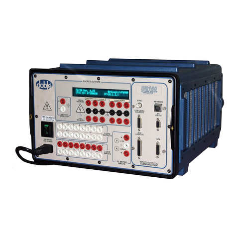
doble F6150 User manual

Doble Engineering Company
85 Walnut Street
Watertown, Massachusetts 02472-4037
USA
72A-2543-01 Rev. F 12/2010
F6150
Power System Simulators
User Guide

F6150 Power System Simulators User Guide
ii 72A-2543-01 Rev. F 12/2010
Important Notice
This User Guide (“Guide”) and the Doble®trademark are the sole property of the Doble Engineering
Company (“Doble”) and, along with the subject matter to which they apply, are provided for the
exclusive use of Doble Users (“User”) as a result of an accepted sales order or under an agreement for
Doble test equipment and services.
In no event does Doble assume liability for any technical or editorial errors or omissions. Doble shall in
no event be liable for direct, indirect, incidental, or consequential damages arising out of reliance,
inaccurate third party information or the inability of the User to use this Guide properly.
Copyright laws protect this Guide; all rights are reserved. No part of this Guide shall be reproduced,
stored in a retrieval system, or transmitted by any means, electronic, mechanical, photocopying,
recording, or otherwise without written permission from Doble.
Doble and the Doble logo are registered in the U.S. Patent and Trademark Office and are trademarks of
the Doble Engineering Company.
Doble is providing the information contained herein for reference purposes only. Doble makes no
warranty or representation that the Guide will meet the User's requirements. This Guide is
intended to provide a basic understanding and general application of the principles set forth
herein. Comments contained herein relating to safety represent minimum guidelines, and should
never be compromised; however, it is foreseeable that the minimum safety guidelines may be
supplemented in order to conform to User's company safety and compliance regulations. User is
responsible for applying the information contained herein in strict accordance with industry as
well as User's company compliance and safety regulations. The techniques and procedures
described herein are based on years of experience with tried and proven methods. However, the
basic recommendations contained herein cannot embrace all conceivable test situations and there
may be instances when Doble should be consulted directly. Doble is not responsible for the
MISUSE OR RELIANCE ON THIS PUBLICATION, ANY OPINIONS CONTAINED HEREIN,
OR AS A RESULT OF MODIFICATION BY ANYONE OTHER THAN DOBLE OR AN
AUTHORIZED DOBLE REPRESENTATIVE. UNDER NO CIRCUMSTANCES WILL
DOBLE BE LIABLE TO ANY USER FOR ANY DAMAGES, INCLUDING WITHOUT
LIMITATION, PERSONAL INJURY OR PROPERTY DAMAGE CAUSED BY THE
PRODUCT, ANY INCIDENTAL OR CONSEQUENTIAL DAMAGES, EXPENSES, LOST
PROFITS, LOST SAVINGS, OR OTHER DAMAGES ARISING OUT OF THE USE OF OR
INABILITY TO USE THIS GUIDE.
Copyright © 2010 Doble Engineering Company
All Rights Reserved

Warranty
72A-2543-01 Rev. F 12/2010 iii
Warranty
Equipment Limited Warranty
Doble warrants the products that it delivers to be free from defects in material and workmanship for a
period of one (1) year from the date shipped from the Doble facility. Equipment delivered under a
valid and duly executed Doble Service and Equipment Agreement will be replaced as set forth in said
agreement.
During the one-year warranty period, Doble will repair or replace, at its option, any defective products
or components thereof at no additional charge, provided that the product or component is returned,
shipping prepaid, to Doble. The Purchaser is responsible for insuring any product or component so
returned and assumes the risk of loss during shipment. All replaced products and components become
the property of Doble.
THIS LIMITED WARRANTY DOES NOT EXTEND TO ANY PRODUCTS WHICH HAVE
BEEN DAMAGED AS A RESULT OF ACCIDENT, MISUSE, ABUSE, OR AS A RESULT OF
MODIFICATION BY ANYONE OTHER THAN DOBLE OR AN AUTHORIZED DOBLE
REPRESENTATIVE.
EXCEPT AS EXPRESSLY SET FORTH ABOVE, NO OTHER WARRANTIES, EXPRESSED
OR IMPLIED, ARE MADE WITH RESPECT TO THE PRODUCT INCLUDING, BUT NOT
LIMITED TO, ANY IMPLIED WARRANTIES OF MERCHANTABILITY AND FITNESS
FOR A PARTICULAR PURPOSE. DOBLE EXPRESSLY DISCLAIMS ALL WARRANTIES
NOT STATED HEREIN. IN THE EVENT THE PRODUCT IS NOT FREE FROM DEFECTS
AS WARRANTED ABOVE, THE PURCHASER'S SOLE REMEDY SHALL BE REPAIR OR
REPLACEMENT AS PROVIDED ABOVE. UNDER NO CIRCUMSTANCES WILL DOBLE
BE LIABLE TO THE PURCHASER OR ANY USER FOR ANY DAMAGES, INCLUDING
WITHOUT LIMITATION, PERSONAL INJURY OR PROPERTY DAMAGE CAUSED BY
THE PRODUCT, ANY INCIDENTAL OR CONSEQUENTIAL DAMAGES, EXPENSES, LOST
PROFITS, LOST SAVINGS, OR OTHER DAMAGES ARISING OUT OF THE USE OF OR
INABILITY TO USE THIS PRODUCT.
Software Limited Warranty
Doble warrants that: (i) for a period of one hundred twenty (120) days from the date of shipment from
Doble, the media on which the Software is furnished will be free of defects in materials and
workmanship under normal use; and (ii) for a period of one year from the date of shipment from Doble,
the Software will perform in substantial conformance to its published specifications. This limited
warranty extends only to the original licensee. Licensee’s exclusive remedy and Doble’s entire liability
under this limited warranty will be, at Doble’s option, to repair or replace the Software, or to refund a
pro rata portion of the purchase price. Doble makes no warranty or representation that its software
products will meet Licensee’s requirements, that the operation of the software products will be
uninterrupted or error free, or that all defects in the software products will be corrected.
This warranty does not apply if the software (a) has been altered, except by Doble, (b) has not been
installed, operated, repaired, or maintained in accordance with instructions supplied by Doble, (c) has
been subjected to abnormal physical or electrical stress, misuse, negligence, or accident, or (d) is used
in ultra-hazardous activities.

F6150 Power System Simulators User Guide
iv 72A-2543-01 Rev. F 12/2010
IN NO EVENT WILL DOBLE BE LIABLE FOR ANY LOST REVENUE, PROFIT, OR DATA,
OR FOR SPECIAL, INDIRECT, CONSEQUENTIAL, INCIDENTAL, OR PUNITIVE
DAMAGES, HOWEVER CAUSED AND REGARDLESS OF THE THEORY OF LIABILITY
ARISING OUT OF THE USE OF OR INABILITY TO USE THE SOFTWARE, EVEN IF
DOBLE HAS BEEN ADVISED OF THE POSSIBILITY OF SUCH DAMAGES. In no event shall
Doble’s liability to Licensee, whether in contract, tort (including negligence), or otherwise, exceed the
price paid by Licensee. The foregoing limitations shall apply even if the above-stated warranty fails of
its essential purpose.
Limitation of Remedies
Doble’s entire liability and Purchaser’s exclusive remedy shall be:
1. The replacement of any disks not meeting Doble’s “limited warranty” which are returned to
Doble.
2. If Doble is unable to deliver replacement disks which are free from defects in materials and
workmanship, Purchaser may terminate the license by returning, destroying or deleting the
software product and all copies thereof in any form and affirming compliance with this
requirement in writing, Doble will refund the purchase price.
THE FOREGOING WARRANTIES AND REMEDIES ARE EXCLUSIVE AND ARE IN LIEU
OF ALL OTHER WARRANTIES, TERMS, OR CONDITIONS, EXPRESS OR IMPLIED,
WHETHER ALLEGED TO ARISE BY LAW, BY REASON OF CUSTOM OR USAGE IN THE
TRADE, OR BY COURSE OF DEALING, INCLUDING WARRANTIES, TERMS, OR
CONDITIONS OF MERCHANTABILITY, FITNESS FOR A PARTICULAR PURPOSE,
SATISFACTORY QUALITY, CORRESPONDENCE WITH DESCRIPTION, AND
NONINFRINGEMENT, ALL OF WHICH ARE EXPRESSLY DISCLAIMED.
For equipment maintenance, contact:
Customer Service Manager (Extension 2921)
Doble Engineering Company
85 Walnut Street
Watertown, MA 02472-4037 (USA)
Telephone: 617-926-4900
Fax: 617-926-0528
Email: [email protected]

72A-2543-01 Rev. F 12/2010 v
Contents
1. Introduction ..........................................................................................................1-1
Hardware Architecture ............................................................................................................................... 1-2
F6ControlPanel .......................................................................................................................................... 1-2
USB Driver................................................................................................................................................. 1-4
F6150 Internal Options .............................................................................................................................. 1-4
2. Front Panel ............................................................................................................2-1
Source Outputs........................................................................................................................................... 2-1
Instrument Display .............................................................................................................................. 2-2
Voltage and Current Sources ............................................................................................................... 2-2
Battery Simulator................................................................................................................................. 2-5
Input/Output & Communication ................................................................................................................ 2-6
Network and PC................................................................................................................................... 2-7
Low-Level Sources............................................................................................................................ 2-13
Logic I/O .................................................................................................................................................. 2-15
Logic Outputs .................................................................................................................................... 2-17
Logic Inputs....................................................................................................................................... 2-17
Power........................................................................................................................................................ 2-20
3. Setup and Configuration .....................................................................................3-1
Getting Started ........................................................................................................................................... 3-1
Launching F6ControlPanel.................................................................................................................. 3-2
Using F6000 Configuration........................................................................................................................ 3-4
Convertible V/I Sources ...................................................................................................................... 3-4
Current Sources ................................................................................................................................... 3-5
Predefined Configurations................................................................................................................... 3-5
User-Defined Configurations .............................................................................................................. 3-7
Rules for Source Selection .................................................................................................................. 3-8
Compliance Voltage and Current Range ............................................................................................. 3-8
Timing between State Changes ................................................................................................................ 3-10
4. Troubleshooting ....................................................................................................4-1
General Troubleshooting Techniques......................................................................................................... 4-1
Troubleshooting Flowcharts....................................................................................................................... 4-2
LED Status Indicators ................................................................................................................................4-4
CPU Circuit Boards ............................................................................................................................. 4-4

Contents
vi 72A-2543-01 Rev. F 12/2010
Analog I/O Circuit Board.....................................................................................................................4-7
Voltage and Current Amplifier Circuit Boards ....................................................................................4-8
Power Supply Circuit Board ..............................................................................................................4-10
Component Checkout Procedures.............................................................................................................4-13
Checking the Low-Voltage Power Supply .........................................................................................4-13
Checking the Battery Simulator.........................................................................................................4-15
Checking the Logic I/O Printed Circuit Board ..................................................................................4-16
Checking the Voltage or Current Amplifier Board ............................................................................4-16
Checking the Cooling Fan..................................................................................................................4-16
Resolving Communication Problems .......................................................................................................4-17
Error Types ...............................................................................................................................................4-17
Hardware Errors .................................................................................................................................4-17
Source Errors......................................................................................................................................4-19
System Errors.....................................................................................................................................4-20
5. Field Replacement Procedures ............................................................................5-1
Safety Precautions ......................................................................................................................................5-1
Preparatory Steps ........................................................................................................................................5-4
Removing the Instrument’s Cover .......................................................................................................5-4
Power Up and Perform a Visual Check................................................................................................5-5
Removing and Replacing the Instrument’s Front Panel .............................................................................5-6
Removal ...............................................................................................................................................5-6
Installation............................................................................................................................................5-9
Removing and Replacing the Communications Board.............................................................................5-12
CPU1 and Older CPU2 Instruments ..................................................................................................5-12
Present CPU2 Instruments .................................................................................................................5-13
Removing and Replacing Circuit Boards .................................................................................................5-14
Removal .............................................................................................................................................5-14
Installation..........................................................................................................................................5-15
Removing and Replacing the Battery Simulator ......................................................................................5-18
F6150 with Variable Output Battery Simulator .................................................................................5-18
F6150 with Fixed Output Battery Simulator......................................................................................5-18
Removal .............................................................................................................................................5-18
Installation..........................................................................................................................................5-20
Removing and Replacing the Cooling Fans .............................................................................................5-20
Changing the Initial-Style Fan Assembly ..........................................................................................5-20
Changing the New-Style Fan Assembly ............................................................................................5-22
Verify the Replacement.............................................................................................................................5-25
Replaceable Components and Cables.......................................................................................................5-25

Contents
72A-2543-01 Rev. F 12/2010 vii
6. Safety and Maintenance .......................................................................................6-1
F6150 Rules for Safe Operation................................................................................................................. 6-1
Cleaning the F6150 .................................................................................................................................... 6-2
Customer Service ....................................................................................................................................... 6-2
Returning the F6150................................................................................................................................... 6-3
Appendix A. Firmware Maintenance ....................................................................A-1
Flash Loader.............................................................................................................................................. A-1
Loading New Firmware...................................................................................................................... A-2
Communications Parameters .............................................................................................................. A-3
Flashload Failure Recovery Techniques............................................................................................. A-4
Key Code Update ...................................................................................................................................... A-5
Appendix B. Ethernet Communications ...............................................................B-1
Connecting the Control PC to the F6150 ...................................................................................................B-1
CPU1 Instruments................................................................................................................................B-1
CPU2 Instruments................................................................................................................................B-2
Configuring the Control PC .......................................................................................................................B-2
Set the F6000 IP Address...........................................................................................................................B-6
Appendix C. Global Positioning System ...............................................................C-1
GPS Synchronization .................................................................................................................................C-1
Setting Up Your GPS Equipment...............................................................................................................C-3
Conducting the Test....................................................................................................................................C-4
Appendix D. Specifications .....................................................................................D-1
Sources ...................................................................................................................................................... D-1
Total Sources ...................................................................................................................................... D-1
Convertible Sources............................................................................................................................ D-1
Current Sources .................................................................................................................................. D-2
General ...................................................................................................................................................... D-3
Appendix E. Defining Triggers ..............................................................................E-1
Index ..................................................................................................................Index-1


72A-2543-01 Rev. F 12/2010 ix
List of Figures
Figure 1-1 F6150 Power System Simulator .................................................................................. 1-1
Figure 1-2 F6150 Components ...................................................................................................... 1-2
Figure 1-3 F6ControlPanel ............................................................................................................ 1-3
Figure 1-4 Test Setup with F6ControlPanel, F6150, and Relay under Test ................................. 1-4
Figure 2-1 F6150 Front Panel (Present CPU2 shown) .................................................................. 2-1
Figure 2-2 F6150 Front Panel Source Outputs .............................................................................. 2-3
Figure 2-3 Six 150 VA Sources Mapped from VFD ..................................................................... 2-4
Figure 2-4 Four 150 VA Sources and Four 75 VA Sources Mapped from VFD .......................... 2-4
Figure 2-5 Twelve 75 VA Sources Mapped from VFD ................................................................ 2-5
Figure 2-6 Input/Output & Communication Section ..................................................................... 2-6
Figure 2-7 Serial Connection – Computer to CPU1 or Older CPU2 F6150 ................................. 2-9
Figure 2-8 Serial Connection – Computer to Present CPU2 F6150 ............................................ 2-10
Figure 2-9 Ethernet Connection – Computer to CPU1 F6150 with Switch/Hub ........................ 2-10
Figure 2-10 Ethernet Connection – Computer to Older CPU2 F6150 with Switch/Hub ...............2-11
Figure 2-11 Ethernet Connection – Computer to Older CPU2 F6150 with a
Cat 5 Crossover Cable ................................................................................................2-11
Figure 2-12 Ethernet Connection — Computer to Present CPU2 F6150 with Switch/Hub ......... 2-12
Figure 2-13 Ethernet Connection — Computer to Present CPU2 F6150 with a
Cat 5 Crossover Cable ............................................................................................... 2-12
Figure 2-14 Computer to CPU2 F6150/CPU2 F6300 ................................................................... 2-13
Figure 2-15 Low-Level Source Connections – 3 Voltages and 9 Currents ................................... 2-14
Figure 2-16 Low-Level Source Connections – 3 Voltages and 3 Currents ................................... 2-14
Figure 2-17 Logic I/O Section, Instrument with I/O 1 Board (Option 6841) ............................... 2-15
Figure 2-18 Logic I/O Section, Instrument with I/O 2 Board (Option 6842) ............................... 2-15
Figure 2-19 Logic I/O Section, Instrument with I/O 4 Board (Option 6844) ............................... 2-16
Figure 2-20 Logic I/O Section, Instrument with I/O 5 Board (Option 6845) ............................... 2-16
Figure 3-1 Instrument Display after Successful Bootup ............................................................... 3-2
Figure 3-2 ProTest Menu Bar ........................................................................................................ 3-2
Figure 3-3 F6 Instrument Section of Setup Dialog Box ................................................................ 3-3
Figure 3-4 F6ControlPanel ............................................................................................................ 3-3
Figure 3-5 F6000 Configuration Dialog Box ................................................................................ 3-4
Figure 3-6 Predefined Configurations ........................................................................................... 3-5
Figure 3-7 F6000 Configuration Dialog Box with F6150/F6300 Configuration Selected ........... 3-7
Figure 3-8 User-Defined Configurations ...................................................................................... 3-7
Figure 4-1 Troubleshooting Flowchart – Part 1 ............................................................................ 4-2
Figure 4-2 Troubleshooting Flowchart – Part 2 ............................................................................ 4-3
Figure 4-3 Slot 3 – CPU1 Board ................................................................................................... 4-4
Figure 4-4 Slot 3 – CPU2 Board ................................................................................................... 4-7

x 72A-2543-01 Rev. F 12/2010
Figure 4-5 Slot 4 – Analog I/O Board ........................................................................................... 4-8
Figure 4-6 Slots 5, 6, 7 – Current Amplifier Boards ..................................................................... 4-9
Figure 4-7 Slots 8, 9, 10 – Voltage/Current Convertible Amplifier Boards .................................. 4-9
Figure 4-8 Slot 11 – Power Supply (Type 1) ............................................................................... 4-10
Figure 4-9 Slot 11 – Power Supply with Variable Output Battery Simulator (Type 2) .............. 4-12
Figure 4-10 Connector J20 Test Points at Rear of Backplane (Top View) ................................... 4-14
Figure 4-11 System Error Message ............................................................................................... 4-20
Figure 4-12 System Error Diagnostic Information ........................................................................ 4-21
Figure 5-1 Top View of F6150 Component Orientation – CPU1 and CPU2 ................................ 5-3
Figure 5-2 Rubber Feet at the Back of the Instrument .................................................................. 5-5
Figure 5-3 Internal Components and Capture Rail ........................................................................ 5-5
Figure 5-4 F6150 Ribbon Cables ................................................................................................... 5-6
Figure 5-5 W5 Connector Plugged into AIM Board Extender ...................................................... 5-7
Figure 5-6 W8 Connector and Front Panel Components (Rear View) .......................................... 5-8
Figure 5-7 Rear of Front Panel – Yellow/Green Ground Wires and AC Connectors ................... 5-8
Figure 5-8 Rear of Front Panel – Green/Yellow Ground Wire and 5-Pin Molex Plug ................. 5-9
Figure 5-9 Routing of W6 and W7 Ribbon Cables ..................................................................... 5-11
Figure 5-10 Completed Installation ............................................................................................... 5-12
Figure 5-11 Communications Board(s) Ready for Removal (CPU1 and Older CPU2) ................ 5-13
Figure 5-12 Removing the Communications Board (Present CPU2) ............................................ 5-14
Figure 5-13 Slot 1 – Logic I/O Board Type 1 ............................................................................... 5-15
Figure 5-14 Slot 1 – Logic I/O Board Type 2 ............................................................................... 5-16
Figure 5-15 Slot 1 – Logic I/O Board Type 4 ............................................................................... 5-16
Figure 5-16 Slot 1 – Logic I/O Board Type 5 ............................................................................... 5-17
Figure 5-17 Slot 2 – Analog Input Measurement (AIM) Board .................................................... 5-17
Figure 5-18 Fixed Output Battery Simulator Mounted at the Back of the Instrument .................. 5-18
Figure 5-19 Remove Power Supply and Voltage Amplifiers to Access Battery Simulator .......... 5-19
Figure 5-20 Back Panel after Removal of Battery Simulator ........................................................ 5-19
Figure 5-21 Side View of Instrument before Removal of Cooling Fans ....................................... 5-21
Figure 5-22 Retaining Bracket for Cooling Fans .......................................................................... 5-21
Figure 5-23 Cooling Fans with Wires Connected ......................................................................... 5-22
Figure 5-24 Fan Assembly with Integral Power Supply ............................................................... 5-23
Figure 5-25 Screw Holes on Fan Assembly Rail ........................................................................... 5-24
Figure 5-26 Instrument Chassis with Fan Assembly Removed ..................................................... 5-24
Figure A-1 Flash Loader ................................................................................................................ A-1
Figure A-2 Set Communications Parameters ................................................................................ A-3
Figure A-3 Set Communications Parameters – Network .............................................................. A-3
Figure A-4 Save Communications Settings .................................................................................. A-4
Figure A-5 Key Code Update ........................................................................................................ A-6
Figure A-6 KeySet Dialog Box – Change in Capabilities ............................................................. A-6
Figure A-7 KeySet Dialog Box – Successful Update .................................................................... A-6
Figure A-8 KeySet Dialog Box – Error Message .......................................................................... A-7

72A-2543-01 Rev. F 12/2010 xi
Figure B-1 Alternate 50-Ohm Terminator CPU1 Connections for Coaxial Cable ........................B-1
Figure B-2 Accessing Network Properties .....................................................................................B-2
Figure B-3 Network Dialog Box: Scroll to the TCP/IP Component .............................................B-3
Figure B-4 TCP/IP Properties Dialog Box ....................................................................................B-3
Figure B-5 IP Address and Subnet Mask in TCP/IP Properties Dialog Box .................................B-4
Figure B-6 Successful Ping ............................................................................................................B-5
Figure B-7 Set F6000 IP Address Dialog Box ...............................................................................B-6
Figure C-1 End-to-End Testing with GPS Synchronization ..........................................................C-2
Figure C-2 Equipment Setup for GPS Synchronization ................................................................C-3
Figure E-1 F6 Control Panel Define Triggers Dialog Box ............................................................ E-1
Figure E-2 Set Trigger Logic Dialog Box ..................................................................................... E-1

xii 72A-2543-01 Rev. F 12/2010

72A-2543-01 Rev. F 12/2010 xiii
List of Tables
Table 1-1 F6150 Internal Options ..................................................................................................... 1-4
Table 2-1 150 VA Convertible Sources Configured to Supply Low Current at a
High Compliance Voltage ................................................................................................ 2-3
Table 2-2 Serial and Ethernet Connections for CPU 1 and CPU2 ................................................. 2-8
Table 2-3 Logic Output Details ...................................................................................................... 2-17
Table 2-4 Logic Input Details ......................................................................................................... 2-18
Table 2-8 Low-Level Source Connector Pinout and Parameter Ranges ...................................... 2-20
Table 3-1 Maximum Compliance Voltage for Low-Current Source Combinations ..................... 3-9
Table 3-2 Maximum Compliance Voltage for Low Transient Current
Source Combinations ........................................................................................................ 3-9
Table 3-3 Maximum Compliance Voltage for Current Source Combinations ............................ 3-10
Table 3-4 Maximum Compliance Voltage for Transient Current Source Combinations ........... 3-10
Table 4-1 CPU1 Board LEDs ........................................................................................................... 4-5
Table 4-2 CPU2 Board LEDs ........................................................................................................... 4-6
Table 4-3 Analog I/O Board LEDs ................................................................................................... 4-8
Table 4-4 Type 1 Power Supply Board LEDs ............................................................................... 4-11
Table 4-5 Type 2 Power Supply Board LEDs ............................................................................... 4-12
Table 4-6 Battery Simulator Alternatives ...................................................................................... 4-13
Table 4-7 CPU1 Power Supply Test Points ................................................................................... 4-13
Table 4-8 CPU2 Power Supply Test Points ................................................................................... 4-14
Table 4-9 Connector J20 Test Points .............................................................................................. 4-15
Table 4-10 Hardware Errors .............................................................................................................. 4-18
Table 4-11 Common Source Errors .................................................................................................. 4-19
Table 4-12 System Errors .................................................................................................................. 4-22
Table 5-1 Cable Connections ............................................................................................................ 5-4
Table 5-2 Field-Replaceable Components ..................................................................................... 5-25
Table 5-3 Cable and Adapter Shipping/Replacement List ............................................................ 5-26
Table 5-4 Additional Component Shipping/Replacement List ..................................................... 5-27
Table D-1 Source Configurations for Convertible Sources ............................................................ D-1
Table D-2 Range and sResolution for Convertible Sources ........................................................... D-1
Table D-3 Source Configurations for Current Sources ................................................................... D-2
Table D-4 Ranges and Resolution for Current Sources .................................................................. D-3
Table D-5 General Information ........................................................................................................ D-3

F6TesT 2.20 User Guide
xiv 72A-2543-01 Rev. F 12/2010

72A-2543-01 Rev. F 12/2010 1-1
1. Introduction
The F6150 power system simulator (Figure 1-1) enables you to test any type of protection.
The current amplifier has power to test high-burden electromechanical relays. Concurrently,
the F6150 provides up to 12 sources to test solid-state and multifunction numerical protection.
It can test not only simple voltage, current, and frequency relays but also complex protection
schemes, such as communication-assisted line protection.
Figure 1-1 F6150 Power System Simulator
Configuration of the sources is internal and is independently controlled by a computer to meet
diverse requirements for various relay tests. By combining the current sources in series or
parallel, the F6150 yields higher output for testing high-burden relays or protection schemes.
Eight logic input and eight logic output channels provide the means to evaluate protection
scheme performance. An independent DC battery simulator is also furnished for powering
digital and static relays or meters.
The F6150 has three current amplifiers and three voltage/current convertible
amplifiers.

Chapter 1: Introduction
1-2 72A-2543-01 Rev. F 12/2010
Hardware Architecture
Figure 1-2 shows the components of the F6150.
Figure 1-2 F6150 Components
F6ControlPanel
F6ControlPanel (Figure 1-3) enables you to direct the F6150 from a computer connected to the
instrument’s front panel. It emulates front panel controls, allowing you to configure and
control the instrument’s voltage sources, current sources, logic inputs, logic outputs, and
timers. It also provides settings and controls that accommodate a wide range of test
configurations. You can use the control panel’s intuitive controls to check a relay without an
elaborate test plan.
Front Panel
Logic I/O Board
CPU Board
Analog I/O Board
3 Current Amplifiers
3 Voltage/Current
Power Supply
Cooling Fans (4)
Convertible Amplifiers
Variable Output
Battery Simulator
with Integrated
(VOBS)
with Integrated
DC Power Supply
Analog Input
Measurement
(AIM) Board (Option)

F6ControlPanel
72A-2543-01 Rev. F 12/2010 1-3
A stand-alone version of F6ControlPanel is shipped with each F6000 instrument.
F6ControlPanel is also available from the Tools menu of ProTesT. For complete details on
using F6ControlPanel, see the F6ControlPanel User Guide.
Figure 1-3 F6ControlPanel

Chapter 1: Introduction
1-4 72A-2543-01 Rev. F 12/2010
Figure 1-4 shows a typical system configuration for the software, the instrument, and a relay
under test.
Figure 1-4 Test Setup with F6ControlPanel, F6150, and Relay under Test
USB Driver
New F6150 instruments include a USB connector on the front panel. This connector is used
for serial communication between your computer and the F6150.
For your computer to be able to communicate with the F6150 using the USB serial connection,
you must install the USB driver included on the CD supplied with the instrument or
downloaded from the Doble website (www.doble.com/support/download.html). See the USB
Driver Installation Notice (500-0706) for instructions on installing the driver.
F6150 Internal Options
Ethernet
or USB
Communication
Logic
Inputs
Voltage &
Current
Relay
F6ControlPanel
Communications
Relay
Sources
Logic
Outputs
(Optional)
under Test
Table 1-1 F6150 Internal Options
Option No. Name Description
F6800 Transducer Interface Enables the DC meter inputs on the F6150. Includes Meter
Measurement Studio software.
F6810 High-Power Convertible
Voltage/Current Sources
Provides high-compliance voltage/low current ranges for overcurrent
relay testing. Enables testing of older, high-burden electromechanical
and all 1 amp protection.

F6150 Internal Options
72A-2543-01 Rev. F 12/2010 1-5
aThe option number of the logic I/O board will scroll in the VFD when Firmware 2.21 or greater
(CPU1 instrument) or Firmware 4.21 or greater (CPU2 instrument) is installed.
F6820 Analog Input Measurement
Module
Allows you to collect eight channels of analog and digital data using
the logic input connectors on the front of the F6150.
F6825 High-Speed CPU2 Provides an integrated high-speed (300 MHz) communication
processor, featuring memory controller with 1 MB of synchronous
SRAM (SSRAM) and enhanced 32-bit communication processor
module with a 10/100 Mbps RJ-45 Ethernet link.
F6841 Logic I/O Board Type 1 (04S-0672-01)a
F6842 Logic I/O Board Type 2 (04S-0742-01)a
F6844 Logic I/O Board Type 4 (04S-0820-01)a
F6845 Logic I/O Board Type 5 (04S-0837-01)a
F6860 IEC 61850 GSE Interface
Module
Supports inputs from protective relays that support IEC 61850
protocol.
F6875 Variable Output Battery
Simulator (VOBS)
Provides a fully adjustable variable battery supply from 6 to 300 V DC
@ 90 W.
F6885 Global Positioning System
(GPS) Satellite Receiver
Interface
Enables the GPS receiver interface in/out on the F6150. Requires
connection to the F6895 GPS Antenna (F6895).
F6895 GPS Antenna The antenna/receiver that is connected to the F6150 and receives the
GPS signal.
F6909 Control Panel Enable Permits F6ControlPanel to communicate with the F6150.
F6910 Simulator Control and
Automation Module
Permits the F6150 to communicate with automated software
applications like F6ControlPanel.
Table 1-1 F6150 Internal Options (Continued)

Chapter 1: Introduction
1-6 72A-2543-01 Rev. F 12/2010
Other manuals for F6150
1
Table of contents
Other doble Power Supply manuals
Popular Power Supply manuals by other brands

Peavey
Peavey Performance Series operating instructions

Castolin Eutectic
Castolin Eutectic CastoTIG Operating manual / spare parts list

PeakTech
PeakTech 6225 A Operation manual

Signtex
Signtex CRSAC-MM Series Installation instructions and owner's manual

Atec
Atec 6275 KWIKSTART user manual

Elektro-Automatik
Elektro-Automatik PSB 10060-1000 4U operating guide