manuals.online logo
Brands
  1. Home
  2. •
  3. Brands
  4. •
  5. DockCraft
  6. •
  7. Boating Equipment
  8. •
  9. DockCraft 100 Series User manual

DockCraft 100 Series User manual

This manual suits for next models

1

Other DockCraft Boating Equipment manuals

DockCraft DockSider DS200 User manual

DockCraft

DockCraft DockSider DS200 User manual

DockCraft The DockSider 400 Series Assembly instructions

DockCraft

DockCraft The DockSider 400 Series Assembly instructions

DockCraft DockSider User manual

DockCraft

DockCraft DockSider User manual

Popular Boating Equipment manuals by other brands

SureShade RTX Installation instructions manual

SureShade

SureShade RTX Installation instructions manual

Ideal Windlass CWM Installation, operation & maintenance instructions

Ideal Windlass

Ideal Windlass CWM Installation, operation & maintenance instructions

Access BIMINI Assembly instructions

Access

Access BIMINI Assembly instructions

Floe VSD 6000 Assembly instructions

Floe

Floe VSD 6000 Assembly instructions

Exalto 240BS manual

Exalto

Exalto 240BS manual

Faun C40 Trackway user manual

Faun

Faun C40 Trackway user manual

Humphree HCS-5 installation manual

Humphree

Humphree HCS-5 installation manual

Vetus BOW4512D Operation manual and installation instructions

Vetus

Vetus BOW4512D Operation manual and installation instructions

Dock Doctors SLIDING BOARDING STEP Assembly instructions

Dock Doctors

Dock Doctors SLIDING BOARDING STEP Assembly instructions

Mastervolt Mass Combi 12/2000-100 Quick installation

Mastervolt

Mastervolt Mass Combi 12/2000-100 Quick installation

SeaView PM5-FMD-8 installation instructions

SeaView

SeaView PM5-FMD-8 installation instructions

Hobie Mirage 360 manual

Hobie

Hobie Mirage 360 manual

Zattini Group bamar BOXTRON E14S Use and maintenance instruction manual

Zattini Group

Zattini Group bamar BOXTRON E14S Use and maintenance instruction manual

Hobie Getaway Hatch instructions

Hobie

Hobie Getaway Hatch instructions

NUCANOE 3005 Assembly instructions

NUCANOE

NUCANOE 3005 Assembly instructions

Floe V1600 PWC Assembly instructions

Floe

Floe V1600 PWC Assembly instructions

Westland T-Top Console Cover installation manual

Westland

Westland T-Top Console Cover installation manual

Furuno TZTL12F installation manual

Furuno

Furuno TZTL12F installation manual

manuals.online logo
manuals.online logoBrands
  • About & Mission
  • Contact us
  • Privacy Policy
  • Terms and Conditions

Copyright 2025 Manuals.Online. All Rights Reserved.

TM
“The DockSider”
Patented
Assembly, Installation, Setup, and Operating Instruction
OM CR 100 –7-11-2021
- Canoe Rack Bolt On Model; Series 100 -
Some
Assembly
Required
•Holds Canoes up to 100 pounds.
•For Docks with Wood or Composite Wood Decking.
•Docks with Aluminum or Vinyl Decking need added support
•Designed for standard dock decking thickness of up to 1 ½ inches.
•Tools are required (Drill with 1/2 drill bit) for initial installation
A Canoe Lift and Dock Storage Rack
Model CR 100 - Bolt On Mount
- Holds your Canoe 5 to 17 inches below the dock surface.
- Includes a Pulley System which reduces the Pull required to Lift
- Accommodates Freeboard (Dock Surface to Water Level) height up to 36 inches.
Please read these instructions carefully before using this product and save this
manual for future use.
For assistance, please call: 585 –734 –7374
Or send email to: info@DockCraft.com
DockCraft Industries LLC
3694 Nibawauka Beach
Canandaigua, New York 14424
Page 1 of 15
Table of Contents
Page
“The DockSider”TM
oSafeguards 2
oWarranty 3
oPart List 3
oAssembly Instructions 4
oInstallation –CR 100 7
oSetup 8
oOperation 11
oBolt On Mount Dock Configuration Guide (Reference –Read first) 13
IMPORTANT SAFEGUARDS
1. READ ALL INSTRUCTIONS BEFORE USING THE “The DockSider”TM.
2. The intended use of the product is to store a Canoe on the side of a boat dock.
Do not use this product for other than its intended use.
3. The maximum weight of Canoe to be racked in “The Docksider” TM shall not
exceed 100 pounds.
4. “The Docksider” TM Stainless Steel Model is best for Salt Water applications.
5. Canoes should not contain more than one quarter inch (1/4”) of water inside
when storing in the “The DockSider”TM. Product Damage could result to the
“The DockSider”TM, if this is not followed the Warranty will be voided. If your
Canoe contains excess amounts of water (capsized or other), roll canoe over to
empty.
6. To ensure proper use, do not attempt to modify this product in any manner.
Please refer to the manual if questions arise.
7. If further assistance is needed, please contact DockCraft Industries prior to use.
8. Do not allow children or adults to lean on, play on, around, or with the “The
DockSider”TM while a Canoe is loaded or unloaded. Serious injury or damage to
product, docks, and people could result if this warning is not followed.
9. Store only one Canoe in “The DockSider”TM.
10. If the DockSider is not working properly, please contact DockCraft Industries
immediately for assistance.
11. Do not enter or exit your Canoe when your Canoe is engaged within
“The DockSider” ; in the loading or storage position.
12. Do not install your Canoe Storage Rack such that “The DockSider” is near or
in contact with any electrical or Dock Structural components.
Page 2 of 15
Limited Warranty
What does your warranty cover?
•Any defect in materials or workmanship when used for the intended purpose of storing
kayaks on the side of a boat dock under normal use and conditions.
•The warranty is limited to the original purchaser.
For how long after the original purchase?
•One year
What will we do?
•Provide you with a replacement part at no charge for any part found defective in
materials or workmanship.
How do you make a warranty claim?
•Please contact DockCraft Industries for a Return Material Authorization (RMA) number
before returning items. A shipping address will be provided at that time.
What does your warranty not cover?
•Damage from failures that occur as a result of improper assembly, failure to properly
adjust and operate, misuse or neglect of product’s intended purpose.
•Product which has been modified in any manner.
•Safeguards are not followed
•The warranty is not valid if you are not the original purchaser.
•Cosmetic defects
“The DockSider”TM PARTS LIST –
Canoe Lift & Storage Rack; Series 200
Remove all parts from the box and remove the dock mount from the pivot lateral by
unwrapping the stretch wrap.
If any parts are missing from the package (in type or quantity), do not assemble and contact
DockCraft Industries immediately.
Model CR200 –
2
1
3
Parts Diagram
1 –Canoe Lifting Assembly
2 - Handle Assembly (1)
3 - Pivot Lateral Cradle Assembly (2)
4 –Bolt On Dock Mount Assembly (2)
5 –Hardware Kit
Page 3 of 15
4
Assembly Instructions
Attach Cradle Handle :
1 - Position Handle over Cradle.
2 - Slide the Handle over extension on Cradle.
3 - Depress Snap Button on Cradle.
4 - Seat Handle until Snap Button pops through the Handle hole.
5 - Repeat process for the other side Cradle.
Steps 1 –4
Snap Button
Cam Buckle
Canoe Rack
Notes - Lifting Straps are on the inside
Canoe Rack –Shorter Legs on the inside
Insert Clevis Pins and Retaining Rings on Pivot Lateral:
6 –If the Water Level is 10 to 25 inches below your Dock Decking -
Insert Clevis Pin through Hole 2 in Pivot Lateral such that the head is between the
Pivot Lateral and Cradle, attach circular retaining ring through the hole in the end
of the clevis pin.
7 –If the Water Level is 25 inches or greater from the Dock Decking –
Insert Clevis Pin through Hole 4 in Pivot Lateral such that the head is between the
Pivot Lateral and Cradle, attach circular retaining ring through the hole in the end
of the clevis pin. Canoe Rack
Page 4 of 15
Cradle
Handle
Pivot
Lateral
Circular
Retaining
Ring
Hole 4
Hole 2
Hole 4
Hole 2
Clevis Pin
Head
Clevis Pin
Head
Circular
Retaining Ring
Assembly Instructions - continued
Thread Webbing through Cam Buckle :
8 –Obtain one of the Cam Buckles and Depress Lever
9 –Thread Webbing through opening in the Cam Buckle
Ensure that the Single Bar on the Web Keeper is positioned as shown.
10 –Pull webbing through the Cam Buckle until the pre-marked line is in position with
the cam buckle.
11 –Repeat Steps 6 –8 to thread the webbing through the other Cam Buckle.
Steps 8 - 11
Assemble the Lifting Assembly to the Rack Assembly
Page 5 of 15
Remove mini wrap and rotate channels as shown Snap buttons on this end
Align Lifting Assembly with Pivot Laterals,
depress Snap Buttons and seat Completed Assembly
Start by assembling the pulley to the webbing strap in the middle of the lifting assembly:
1
0
Remove the wing nut and push the screw so that it clears the side plate,
Rotate the side plate such that the nylon spacer and screw is exposed.
Slide the round spacer behind the webbing strap on the cross bar. Rotate the side plate back
in position, push the screw through the hole and secure with the wing nut.
Assembly Instructions –continued
Attach the rope to the Pulley System. This Can be done now or after the unit is assembled to the dock.
Get the rope and tie two half knot next to the pulley assembly on the cradle handle.
The knot should be on the side of the pulley handle that has the head of the screw mounting the pullies.
Slide knot next to pullies, and thread Rope should be on top of pulley on Lifting Structure side,
When complete, coil the rope and secure it to the Lifting Structure with the Velcro strap.
Tying two half hitches
Wrap the rope Pass the end Wrap it around Tighten to
Around the cradle handle Through the loop the standimg part Complete
Tying a overhand knot on the loose end will give added security.
Thread the Pulleys
Page 6 of 15
Install the TOGGLER® brand SNAPTOGGLE® anchor *
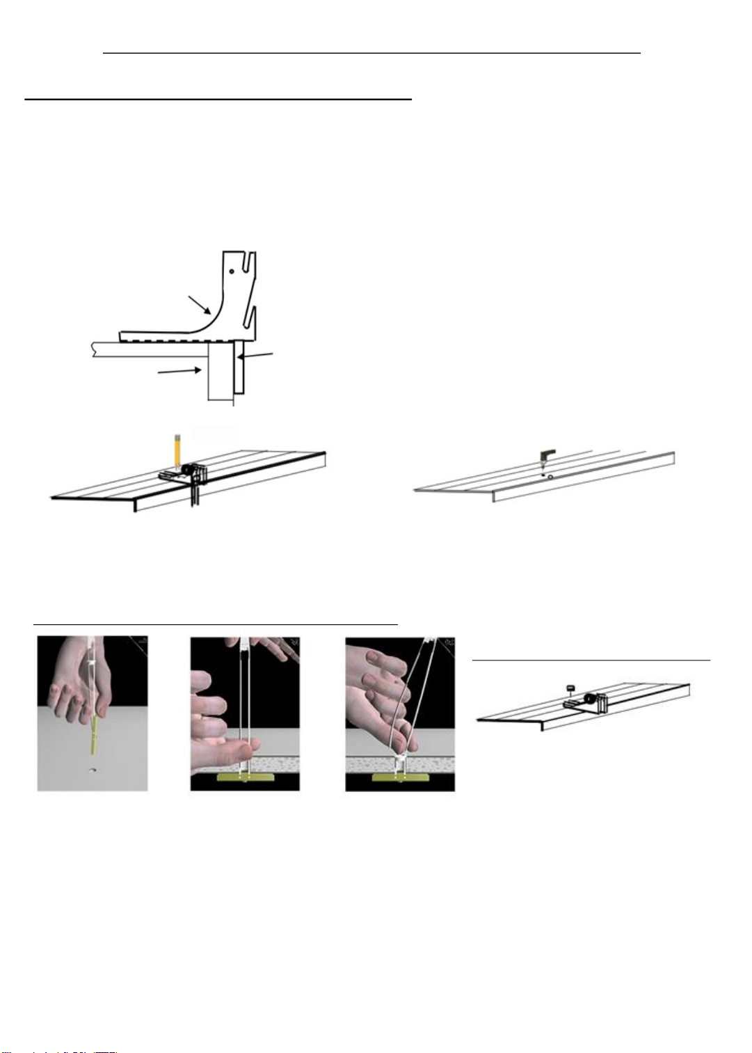
Secure Surface Mount to Dock
Secure Dock Surface Mount with
washers and ¼ - 20 screws provided (2)
Use 7/16 wrench or socket.
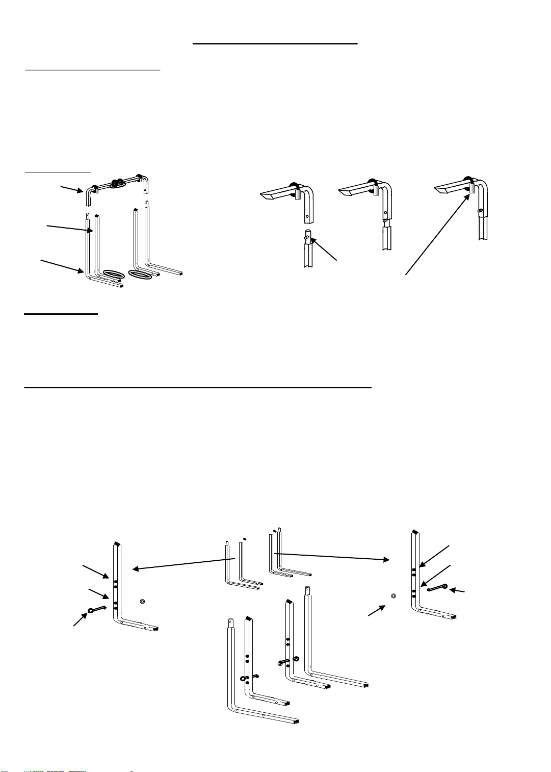
Hold metal channel Hold ends of straps Snap straps at wall
flat alongside plastic between thumb and by pushing side to
straps and slide forefinger and pull side, snapping off
channel through hole. toward you until straps level with
Minimum clearance channel rests flush flange of cap.
behind wall: 1-7/8" behind decking. Slide
plastic cap along straps
with other hand until
flange of cap is flush
with decking.
Installation Procedure for Your - Series 100 Docksider
Series 100 –Bolt On Dock Mount Installation
Page 7 of 15
Note:
If you have a wooden structure under
your decking at the 2 ¼ inch location,
you may want to consider using a lag
bolt.
At the install position align Dock Mount as shown above Drill ½ diameter holes through Dock Decking Surface
With a pencil scribe the hole locations (2) on dock surface Ensure there are not any electrical or structural
While the dock mount is positioned as shown above components near the hole you are drilling. Also
check 26 to 32 inches away where you will mount the
second Dock Surface Mount
Dock Surface Mount
Dock Mount is
Your Dock positioned against the
side of your dock
1 - Select a position on your dock where you choose to mount your Kayak Storage Rack.
Ensure there are not any electrical or structural components in the area.
2 - The Docksider should be mounted on 1 section of your dock.
3 - Make sure the wood on your dock is solid (not cracked or rotting) at the installation
position.
4 - Ensure there are no obstructions above or below your dock.
5 - Place one Dock Mount on your Dock and position as shown below
6 - Install Note:
- Use a ½ in. diameter drill for hardware provided
- Use a 1/8 in. diameter drill for pilot for ¼ lag bolts
- Use a ¼ in. diameter drill for ¼ machine screws and nuts
* "U.S. Patent no. 6,161,999 and foreign counterparts thereof. Other patents pending. TOGGLER & typeface
and SNAPTOGGLE are worldwide registered trademarks of Mechanical Plastics Corp."
CR 100
Installation is Complete and you are now ready for the Final Adjustments
Latch Plate
Installation - Continued
7 –Similarly to Step #6, Mount the second Dock Mount
Position the second dock mount as shown above Mark and drill as described in Step 6
Install Snaptogglers and secure mount to dock with screws.
Align Cradle Assembly with the installed Dock Mounts
Engage the pins on the Pivot Laterals in top slot of the Dock Mounts and seat.
Note, rotate the Latch Plates, to prevent the cradle from rotating into the water.
If the distance to the water from the dock decking is:
10 to 22 inches: insert clevis pin in 2nd hole of the pivot lateral into the top Slot of the mounting bracket.
17 to 29 inches: insert clevis pin in 2nd hole of the pivot lateral into the bottom Slot of the mounting bracket
20 to 31 inches: insert clevis pin in the 4th hole of the pivot lateral into the top Slot of the mounting bracket
25 to 37 inches: insert clevis pin in 4th hole of the pivot lateral into the bottom Slot of the mounting bracket
Adjust if required - up or down - based on your specific watercraft or if your water level changes significantly
throughout the season.
Page 8 of 15
SETUP of “The DockSider”TM
Now that the installation is complete, it is now time to SETUP your Kayak Rack to “fit”
your Kayak.
Kayak Storage Rack to Water Level Adjustment:
Canoe Rack
To “Lock” the Brackets and Pivot Laterals together insert “Locking Pin” on both sides of unit.
If Clevis Pin with Circular Retaining Ring in Hole 2 or 4 of Pivot Lateral is seated in the Top Slot.
SETUP of “The DockSider”TM -continued
Insert 2nd Clevis Pin through hole in bracket
and secure with
“R” Retaining Clip on opposite side.
If Clevis Pin with Circular Retaining Ring in Hole 2 or 4 of Pivot Lateral is seated in the Bottom Slot
Insert 2nd Clevis Pin through hole in bracket
and secure with
“R” Retaining Clip on opposite side.
Page 9 of 15
Webbing Length Adjustment :
On page 3 you set the webbing mark at the cam buckle.
This setting is a nominal setting for kayaks with a width of 27 to 29 inches. Based on the width and
contour of your kayak, this setting may vary.
This setting has 2 purposes:
1 –To accommodate the size
and contour of your Kayak
2 –To allow your Kayak to sit at
an angle to minimize rain
entering the Kayak and
therefore collect in the cockpit
3 –Load your Kayak into your rack and rotate to the Kayak Storage Position by:
a: Rotating the Cradle toward the water such that the handle is parallel with the water.
With the Dockside Operation model do this using the tether strap.
With the Waterside Operation model do this by standing in the water and centered on your rack,
grasping the handle and rotating toward you.
Page 10 of 15
Webbing Length Adjustment : continued
To Short To Long To Long
The webbing strap length is:
Note: If the dock surface to water height is between 10 and 15 inches, the figure above on the left maybe the
best that can be achieved with the contour of your kayak.
To adjust the Length of the webbing straps:
Depress Cam Buckle lever and pull in the
direction shown
The ideal storage position should look like:
Pull to Lengthen
Pull to Shorten
Never adjust such that the bottom of your Kayak is closer than 2 inches to the end of the cradle.
Note: the closer the kayak is to the end of the cradle, the greater the reach of operation.
Suggestion: If the Webbing length is to short, lengthen significantly.
Manually, position your kayak in the storage position at the desired angle, and then tighten
straps by shortening.
SETUP of “The DockSider”TM - continued
3 –Continued
b: Float your kayak into the rack (between the handle and the webbing) such that the cockpit
seat is centered in the cradle.
c: Lift your kayak just out of the water. If your kayak wants to lean to the right or left, check the straps
to see if there is an excessive amount of strap on the side that’s leaning, if so shorten. Also you may
want to adjust the position of the kayak in the rack. If the lean is to the left, reposition the kayak
slightly to the right to have the center of gravity positioned between the straps. Reposition the kayak to
the left if the lean is to the right. By holding the handle with both hands, you can “Feel” if there is
more weight on one side versus the other. Remember this positioning for normal operation.
d: Grasp the center of the cradle or use tether strap and SLOWLY rotate the handle to the Cradle / Kayak
storage position. Rotate SLOWLY, to understand the “feel” of the lift when your kayak rotates toward
the Dock. As the Kayak starts to rotate, grasp the top of your Kayak and guide to its storage position.
On the Dockside Operation model, rotate Latch Plates (both sides) into position to maintain the
position of the Kayak and Rack.
If your Kayak in it’s storage position looks like one of these illustrations: