LOAD CABLE feeds
power to the other
receptacle
SIDE WIRE 3/4” (1.9cm)
Loop clockwise
2/3 of the way
around screw
PLEASE READ THESE INSTRUCTIONS COMPLETELY BEFORE GETTING STARTED
1. What is an Interlock Outlet?
An interlock outlet is dierent from a conventional receptacle in that it requires
input from an external switch or sensor in order to supply power, such as a
Smoke and Heat Sensor. If the switch/sensor is not connected, or if it is not
detecting a safe condition, there will be no power supplied to the receptacle
and a red LED will illuminate on the front of the unit. When the switch/sensor is
satised, power is supplied and a green LED illuminates.
Safety Interlock Outlet Installation Instructions
To prevent severe shock or electrocution always turn the power OFF at
the service panel before working with wiring.
Use this Safety Interlock Outlet with copper or copper-clad wire. Do not
use it with aluminum wire.
Do not install this Safety Interlock Outlet on a circuit that powers life
support equipment because if the outlet trips, it will shut down the
equipment.
Must be installed in accordance with national and local electrical codes.
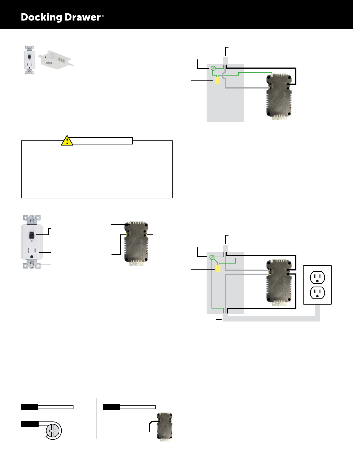
2. Interlock Outlet Anatomy
CAUTION – READ CAREFULLY
3. Should you install it?
Installing an interlock outlet can be more complicated than installing a
conventional receptacle. Make sure that you:
• Understand basic wiring principles and techniques
• Can interpret wiring diagrams
• Have circuit wiring experience
• Are prepared to take a few minutes to test your work, making sure that you
have wired the outlet correctly and that it works as intended.
If you aren’t completely comfortable with the above, please consult a licensed
electrician.
4. Turn the power o
Plug in an electrical device such as a lamp or hair dryer into the receptacle on
which you are working. Turn the lamp or hair dryer ON. Then go to the service
panel and nd the breaker that protects that receptacle. Place the breaker in the
o position and mark it with something to let others know not to turn it back on.
The lamp or hair dryer should turn o if you have the correct breaker selected.
Next, plug the electrical device into the other receptacle to make sure the power
is o at BOTH receptacles. If the power is not o, call an electrician to complete
the installation.
5. Connect the wires. Choose from Option A OR Option B:
INTERLOCK
SWITCH
CONNECTOR
GROUND
Green
Terminal
Green or Bare
Copper Wire
HOT (LINE)
Brass
Terminal
Black wire
NEUTRAL
Silver
Terminal
White wire
Front View Back View
Connect the LINE cable wires to the LINE terminals:
• The white wire connects to the WHITE terminal (Silver)
• The black wire connects to the HOT terminal (Brass)
Connect the grounding wire (only if there is a grounding wire):
• For a box with no grounding terminal (diagram not shown): Connect the LINE
cable’s bare copper (or GREEN) wire directly to the grounding terminal on the
Safety Interlock Outlet
• For a box with a grounding terminal (diagram shown above): Connect a 6-inch
bare copper (or GREEN) 12 or 14 AWG wire to the grounding terminal on the
Safety Interlock Outlet. Also connect a similar wire to the grounding terminal
on the box. Connect the ends of these wires to the LINE cable’s bare copper (or
GREEN) wire using a wire connector. If these wires are already in place, check the
connections.
Complete the installation:
• Fold the wires into the box, keeping the grounding wire away from the WHITE
and HOT terminals. Screw the receptacle to the box and attach the faceplate.
• Go to step 6
OPTION B: Two Cables (4 or 6 wires entering the box)
LINE CABLE brings power to
the Safety Interlock Outlet
BLACK
GROUNDING
CONNECTION TO BOX
(if box has a grounding
terminal)
WIRE
CONNECTOR
ELECTRICAL
BOX
WHITE
BLACK
WHITE
About Wire Connections
BACK WIRE 5/8” (1.6cm)
FOR SIDE WIRE:
OPTION A: One Cable (2 or 3 wires entering the box)
LINE CABLE brings power to
the Safety Interlock Outlet
BLACK
HOT HOT
GROUNDING
CONNECTION TO BOX
(if box has a grounding
terminal)
WIRE
CONNECTOR
ELECTRICAL
BOX
WHITE
FOR BACK WIRE:
Insert bare wire fully and
tighten terminal clamp
on conductor ONLY
Connect the LINE cable wires to the LINE terminals:
• The white wire connects to the WHITE terminal (Silver)
• The black wire connects to the HOT terminal (Brass)
Connect the LOAD cable wires to the LOAD terminals:
• The white wire connects to the WHITE terminal (Silver)
• The black wire connects to the HOT terminal (Brass)
Connect the grounding wire (only if there is a grounding wire):
• Connect a 6-inch bare copper (or GREEN) 12 or 14 AWG wire to the grounding
terminal on the Safety Interlock Outlet. If the box has a grounding terminal, also
connect a similar wire to the grounding terminal on the box. Connect the ends of
these wires to the LINE or LOAD cable’s bare copper (or GREEN) wire using a wire
connector. If these wires are already in place, check the connections.
Complete the installation:
• Fold the wires into the box, keeping the grounding wire away from the WHITE
and HOT terminals. Screw the receptacle to the box and attach the faceplate.
• Go to step 6
WITH SMOKE &
HEAT SENSOR
6015-4000W
GREEN/BARE
NEUTRAL
NEUTRAL
GREEN/BARE
LED INDICATOR
NEMA 5-15
RECEPTACLE
MOUNTING
BRACKET


