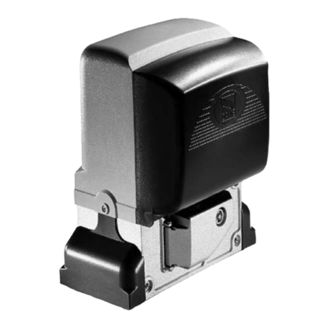
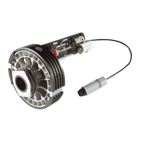
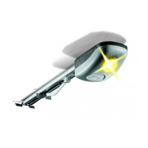
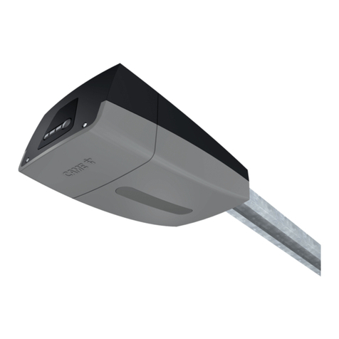
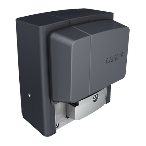
CAME C Series User manual

Documentazione
Tecnica
47
rev. 3.3
12/2003
©
CAME
CANCELLI
AUTOMATICI
C 100 / C BY / C BYT
CANCELLI AUTOMATICI
ITALIANO/ENGLISH/ESPAÑOL
119C47-1
SERIE C |
C SERIES
|
SERIE C
75
3
2
486 1 6
TX
TX
RX
RX
4x1
2x1
2x1
4x1
6x1,5 2x1,5
TRG58
3x1
3x1,5
230V
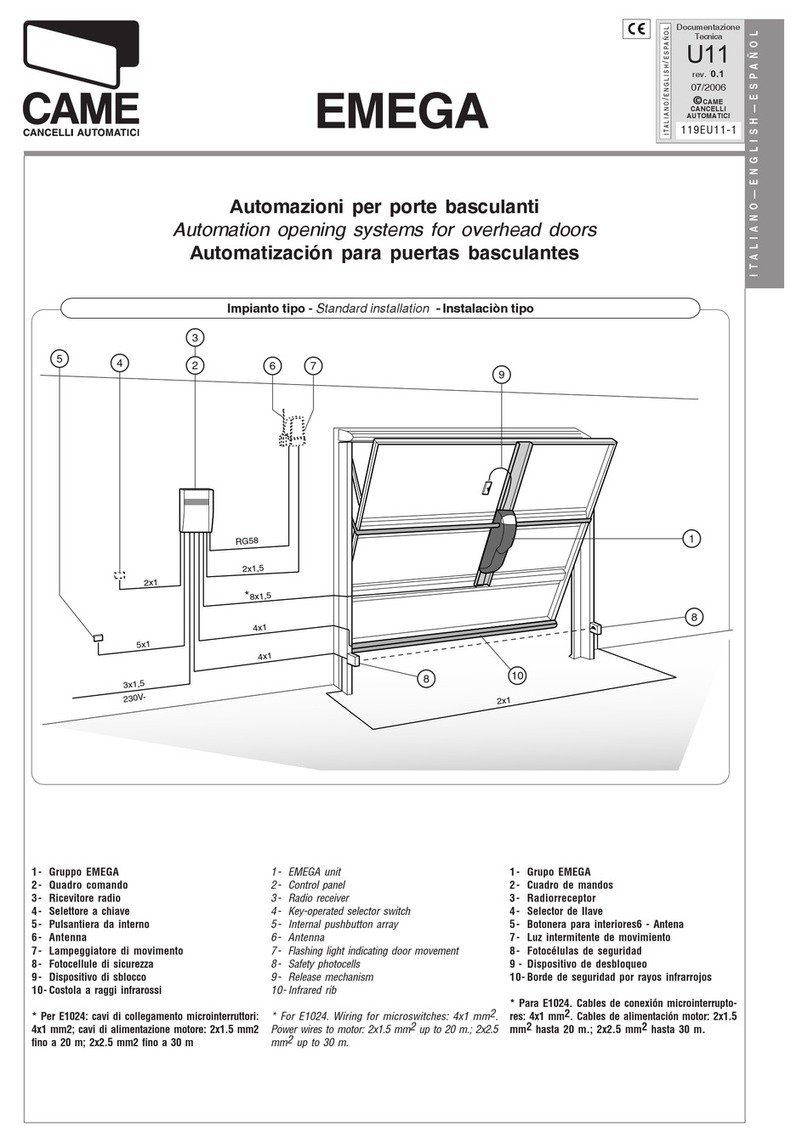
1. Gruppo C
2. Quadro comando
3. Ricevitore radio
4. Lampeggiatore di movimento
5. Antenna
6. Fotocellule di sicurezza
7. Selettore a chiave
8. Maniglia di sblocco
1. C unit
2. Control panel
3. Radio receiver
4. Flashing movement warrning light
5. Antenna
6. Safety photocells
7. Key-operated selector switch
8. Release handle
1. Grupo C
2. Cuadro de mando
3. Radioreceptor
4. Làmpara intermitente de movimiento
5. Antena
6. Fotocélula de seguridad
7. Selector con Ilave
8. Tirador de desbloqueo
Automazioni per applicazioni industriali
Automation systems for industrial applications
Automatización aplicaciones industriales
Impianto tipo -
Standard installation -
Instalaciòn tipo
Impianto tipo
Sandard installation
Instalacion tipo

-2-
ITALIANO • ENGLISH • ESPAÑOL
Caratteristiche generali
Attenzione! Controllate che le apparecchiature di comando, di sicurezza e gli accessori siano originali CAME; ciò
garantisce e rende l'impianto di facile esecuzione e manutenzione.
Accessori di completamento:
ZC3-ZC5-ZM2 quadro comando per C BY - C 100.
ZT4 quadro comando per C BYT.
CCT catena da 1/2".
CGIU giunto per catena.
C1-C2S per portoni sezionali.
C1P-C2P per portoni scorrevoli, a scomparsa ed a libro.
C1-C2F per finestre wasistas ed a sporgere.
C1-C2H per serrande.
CMS dispositivo di sblocco con maniglia e cordino comple-
to di chiavi personalizzate.
CGP guida per catena e carter di protezione per portoni
scorrevoli.
Descrizione:
- Motoriduttori idonei alla movimentazione di portoni sezio-
nali, a scomparsa, scorrevoli, a libro, finestre wasistas ed
a sporgere, serrande a scorrimento orizzontale o verticale
con palo rotante.
- Progettati e costruiti interamente dalla CAME Cancelli
Automatici S.p.A.,
- Grado di protezione IP 54.
- Garantiti 24 mesi salvo manomissioni.
Modelli:
C100 - Motoriduttore irreversibile 300W.
CBY - Motoriduttore irreversibile 450W.
CBYT - Motoriduttore irreversibile trifase 600W.
Modelos:
C100 - Motorreductor irreversible 300W.
CBY - Motorreductor irreversible 450W.
CBYT - Motorreductor irreversible trifase 600W.
Descripción:
- Motorreductores idóneos para mover puertas secciona-
les, ocultas, correderas, articulads, ventanas abatibles y
salientes, puertas enrollables con deslizamiento horizon-
tal o vertical con eje rotatorio.
- Diseñado y fabricado enteramente por CAME Cancelli
Automatici S.p.A.,
- Grado de protección IP54.
- Garantizado 24 meses, salvo manipulaciones.
Atención! Comprobar que los equipos de mando, de seguridad y los acesorios sean originales CAME; lo cual garantiza
y facilita el uso y el mantenimiento del aparato.
Características Generales
Accesorios que lo completan:
ZC3-ZC5-ZM2 cuadro de mando para C BY - C 100.
ZT4 cuadro de mando para C BYT.
CCT cadena de 1/2".
CGIU unión para cadena.
C1-C2S para puertas seccionales.
C1P-C2P para puertas correderas, ocultas y articulados.
C1-C2F para ventanas abatibles y salientes.
C1-C2H para puertas enrollables.
CMS dispositivo de desbloqueo con manilla y cuerda con
llaves personalizadas.
CGP guía para cadenay cubierta de proteccion para puer-
tas de corredera.
Description:
- Gearmotors designed to action sectional doors, folding
doors, sliding or hinged doors, wasistas and hinged win-
dows and vertical or horizontal rotating pole shutters.
- Designed and constructed entirely by CAME Cancelli
Automatici S.p.A.
- IP 54 protecting rating.
- Guaranteed for 24 months, unless tampered with by un-
authorized personnel.
Attention! to insure easy installation and conformance with current safety norms, we raccomend installation of CAME
safety and control accessories.
General specifications
Accessories for installation:
ZC3-ZC5-ZM2 control panel for C BY - C 100.
ZT4 control panel for C BYT.
CCT 1/2" chain.
CGIU coupling for chain.
C1-C2S for sectional doors.
C1P-C2P for sliding doors, folding doors, hinged doors.
C1-C2F for wasistas and hinged windows.
C1-C2H for shutters.
CMS release mechanism with handle and cable, complete
with keys.
CGP chain guide and protection casing of sliding gates.
Models:
C100 - 300W non-reversible gearmotor.
CBY - 450W non-reversible gearmotor.
CBYT - 600W three-phase non-reversible gearmotor.
ESPAÑOL
ITALIANO
ENGLISH


-3-
ITALIANO • ENGLISH • ESPAÑOL
210
250
280
k
y
180
133
87
x
353
160
180
C 100C BY/C BYT
205
x
= min. 147 max. 175
y
= min. 186 max. 213
k
= min. 333 max. 388
65
Dati relativi ai valori di alimentazione nomi-
nale.
*Regolabile mediante quadri comando
CAME.
N.B.: in nessun caso può essere affidata
all'irreversibilità del motoriduttore, la sicu-
rezza anticaduta nelle movimentazioni a
scorrimento verticale (es: sezionali).
These technical specifications apply when unit
is powered at nominal voltage.
*Adjustable using CAME control panels.
N.B.: when fitted to vertical-opening doors (e.g.
sectional doors), the non-reversibility of the
gearmotor must never be used as a safety
device to prevent accidental falling. A specific
safety device must be fitted.
Datos relativos a los valores de alimenta-
ción nominal.
*Regulable mediante cuadros de mando
CAME.
NOTA: durante los movimientos con desli-
zamiento vertical (ej: seccionales) no se
puede, en ningún caso, confiar en la irre-
versibilidad del motorreductor para la se-
guridad anticaída.
Caratteristiche tecniche -
Technical features
- Descripción técnica
Tipo Peso Alimentazione Corrente
nominale Potenza Intermittenza
lavoro Rapporto di
riduzione Coppia Velocità di
rotazione Condensatore
Type Weight Power supply Nominal
current Power Duty cycle Reduction ratio Torque Speed of
rotation Capacitor
Tipo Peso Alimentación Corriente
nominal Potencia Intermit.
trabajo Relación
de reduc. Par Velocidad
de rotac. Condensador
Kg V A W % i N.m rpm µF
C 100 8.5 230 2.3 300 30 1/32 26 * 42 20
C BY 18.5 4450 1/30 50 * 45 31.5
C BYT 230 - 400 2 - 1.2 600 50 50 -
Misure di ingombro -
External dimensions
- Dimensiones máximas
Controlli preliminari -
Preliminary checks
- Controlas preliminares
- Controllare che non vi sia attrito tra
parti fisse e mobili e la struttura del
serramento sia adeguatamente robu-
sta.
- Controllare che il percorso dei cavi
elettrici sia eseguito secondo le di-
sposizioni di comando e sicurezza
(vedi impianto tipo).
NOTA: le applicazioni che seguono
sono solo degli esempi in quanto lo
spazio per il fissaggio del motore e
degli accessori varia a seconda de-
gli ingombri e pertanto spetta all'in-
stallatore la soluzione più idonea.
- Check that there is no friction between
moving parts and fixed parts and that
the structure of the door is sufficiently
robust.
- Check that the path of the electrical
wiring is in compliance with the safety
and control instructions (see Standard
installation).
N.B.: the applications shown below are
examples. Since the space available for
installation of the motor and the acces-
sories varies, the installer should se-
lect the most suitable solution.
- Controbar que no haya roce entre
las partes fijas y móviles y la estruc-
tura del cerramiento sea adecuada-
mente robusta.
- Controbar que el recorrido de los
cables eléctricos esté realizado se-
gún las disposiciones de mando y
seguridad (véase instalation están-
dar).
NOTA: las aplicaciones siguientes
son sólo ejemplos, porque el espa-
cio para la fijación del motor y de
los accesorios varía según las di-
mensiones, por lo tanto es deber del
instalador encontrar la solución más
idónea.

-4-
ITALIANO • ENGLISH • ESPAÑOL
CBY/CBYT
CBY/CBYT
Portone sezionale -
Sectional door
- Puerta seccional
1) Portare l'anta a circa metà della
corsa.
2) Adattare il foro del pignone a 36
denti (accessorio C1-C2S) al Ø del
palo-molla e fissarlo con saldatura.
3) Fissare il motore col pignone del-
lo stesso allineato col pignone a 36
denti, sbloccarlo (tirare la staffa A) e
collegare la catena da 1/2" tra i due
pignoni, in modo tale che questa non
sia in tensione.
1) Move the door to approximately the
half-open position.
2) Adapt the hole of the 36-tooth pinion
(C1-C2S accessory) to suit the diame-
ter of the spring-roller and weld into po-
sition.
3) Fit the motor with its pinion, in align-
ment to the 36-tooth pinion. Release the
motor by pulling bracket "A" and con-
nect the 1/2" between the two pinion.
N.B. The chain should be slightly taut.
1) Colocar la hoja a la mitad de la
carrera.
2) Adaptar el agujero del piñón de
36 dientes (accesorio C1-C2S) al Ø
del eje-muelle y fijarlo soldándolo.
3) Fijar el motor con el piñón del
mismo alineandolo con el piñón de
36 dientes, desbloquearlo (tirar del
estribo A) y colocar la cadena de 1/
2" entre los dos piñones de manera
que no esté sometida a tensión.
Con questa applicazione si ottiene:
This application gives the following per-
formance:
Con esta aplicación se obtiene:
Pignone (36 denti)
Pinion (36 teeth)
Piñón (36 dientes)
Palo-molla
Spring-roller
Barra-muelle
Pignone motore
Motor pinion
Piñón motor
Catena da 1/2”
1/2” chain
Cadena da 1/2”
Staffa A
Bracket A
Estribo A Anta
Door
Hoja
Tipo Coppia Giri del pignone Z=36
(con finecorsa di serie) Velocità di rotazione
albero condotto
Type Torque Pinion revolutions Z=36
(with standar limit stop) Speed of rotation
of driven shaft
Typ Par Giros del piñón Z=36
(con final de carrera de serie) Velocidad de rotación
árbol conducido
N·m n° rpm
C 100 62
14
17.5
C BY 120 18.5
C BYT

-5-
ITALIANO • ENGLISH • ESPAÑOL
Fig. A
Finestra wasistas -
Wasistas window
- Ventana abatibles
1) Portare l'anta/e a circa metà della
corsa, fissare il motore e sbloccarlo
(fig. A).
2) Inserire nell'albero di trasmissione
(da 1") il pignone a 15 denti
(accessorio C1-C2F), alineandolo col
pignone motore e fissarlo con
saldatura. Collegare la catena da 1/
2" tra i due pignoni in modo tale che
questa non sia in tensione.
1) Move the wing/s to approximately the
half-open position, fit the motor and
action the release mechanism (fig. A).
2) Fit the 15-tooth pinion (accessory C1-
C2F) to the drive shaft (the 1"), in align-
ment with the motor pinion, and weld
into position. Fit the 1/2" chain to the
two pinions.The chain should be slight-
ly taut.
1) Colocar la hoja/las hojas a la mi-
tad de la carrera, fijar el motor y des-
bloquearlo (fig. A).
2) Introducir en el árbol de transmi-
sión (de 1") el piñón de 15 dientes
(accesorio C1-C2F), alineandolo con
el piñón motor y fijarlo soldándolo.
Colocar la cadena de 1/2" entre los
dos piñones de manera que no esté
sometida a tensión.
This application gives the following per-
formance:
Con questa applicazione si ottiene: Con esta aplicación se obtiene:
Anta
Wing
Hoja
Albero di trasmissione
Drive shaft
Arbol de trasmission
Cremagliera
Rack
Cremallera Catena da1/2”
1/2” chain
Cadena de 1/2” Pignone (15 denti)
Pinion (15 teeth)
Piñón 815 dientes)
Pignone motore
Motor pinion
Piñón motor
Staffa di
fissaggio
Bracket
Estribo de
fijacion
Tipo Coppia Velocità di rotazione albero condotto
Type Torque Speed of rotation of driven shaft
Typ Par Velocidad de rotaziòn à rbol conducido
N·m rpm
C 100 26 42
C BY 50 45
C BYT

-6-
ITALIANO • ENGLISH • ESPAÑOL
C BY/C BYT
1) Inserire all'estremità del palo della
serranda (Ø max. 60.4 mm), la corona
e fissarla con saldatura.
2) Fissare il motore col pignone dello
stesso allineato con la corona,
sbloccarlo (tirare la staffa A) e
collegare la catena da 1/2" tra corona
e pignone motore in modo tale che
questa non sia in tensione.
1) Fit the crown wheel to the extremity
of the rotating pole (max. Ø 60.4 mm)
and weld into position.
2) Fit the motor with its pinion in
alignmentwiththecrownwheel.Release
the motor by pulling bracket "A" and
connect the 1/2" chain between the
crown wheel and the motor pinion. The
chain should be slightly taut.
1) Introducir en el extremo del eje de
la puerta enrollable (Ø máx. 60.4 mm)
la corona y fijarla soldándola.
2) Fijar el motor con el piñón del
mismo alineado con la corona,
desbloquearlo (tirar del estribo A) y
colocar la cadena de 1/2" entre
corona y piñón motor de manera que
no esté sometida a tensión.
Con questa applicazione si ottiene:
This application gives the following
performance:
Con esta aplicación se obtiene:
Corona (60 denti)
60-tooth crow wheel
Corona (60 dientes)
Pignone motore
Motor pinion
Piñón motor
Staffa A
Bracket A
Estribo A
Catena da 1/2”
1/2” chain
Cadena de 1/2”
Palo della
serranda
Rotating pole
Eje de la puerta
Type Coppia Giri della corona Z=60
(con finecorsa di serie) Velocità di rotazione
albero condotto
Type Torque Crown wheel revolutions Z=60
(with standar limit stop) Speed of rotation
of driven shaft
Typ Par Giros de la corona Z=60
(con final de carrera de serie) Velocidad de rotación
árbol conducido
N·m n° rpm
C 100 100
8.5
10.5
C BY 200 11
C BYT
Serranda con palo rotante -
Rotating-pole shutters
- Puerta enrollable con eje rotatorio

-7-
ITALIANO • ENGLISH • ESPAÑOL
C BY/C BYT
B
CGP
Fig. 2Fig. 1
Portone scorrevole a due ante -
Two-wing sliding doors
- Puerta corredera a dos hojas
1) Portare le ante a circa metà della
corsa, fissare il motore e sbloccarlo
(tirare la staffa A).
2) Applicare l'accessorio C1P (per C
100), C2P (per C BY / C BYT) come
segue:
- fissare il rinvio tendicatena opposto
al motore ed in asse con il pignone
dello stesso;
- se presente, fissare la guida per
catena (CGP) tra motore e rinvio;
- applicare la catena (la lunghezza
della catena, deve essere 2 volte la
distanza B). Regolare la tensione
della stessa mediante la vite del
rinvio e bloccare i dadi. N.B.: la
catena non deve essere in tensione;
- fissare gli appositi attacchi (staffe e
piastre) prima alla catena e poi alle
ante e aplicare il carter di protezione
(CGP).
1) Move the wings to approximately the
half-open position and fit the motor.
Release the motor by pulling bracket
"A".
2) Fit accessory C1P (for C 100) or C2P
(for C BY / CBYT) as follows:
- fit the chain tensioner attachment on
theside opposite the motor,in alignment
with the motor pinion;
- position the chain guide (CGP, if
featured) between the motor and the
chain tensioner;
- fit the chain (the length of the chain
should be twice distance "B"). Adjust
the chain tension by turning the screw
on the tensioner, then tighten the nuts
securely. N.B.. the chain should be
slightly taut;
- fit the brackets and plates first to the
chain and then to the wings and fit the
protective cover (CGP).
1) Colocar las hojas a la mitad de la
carrera, colocar el motor y
desloquearlo (tirar del estribo A).
2) Aplicar el accesorio C1P (para
C100), C2P (para CBY / CBYT) de la
siguiente manera:
- fijar el renvío tensor de cadena
opuesto al motor y en eje con el
piñón del mismo;
- si está presente, fijar la guía para
cadena (CGP) entre el motor y el
renvío;
- aplicar la cadena (la longitud de la
cadena debe ser el doble de la
distancia B). Regular la tensión de la
misma mediante el tornillo del renvío
y bloquear las tuercas. Nota: la
cadena no debe estar sometida a
tensión;
- fijar los adecuados ancajes
(estribos y placas) primero a la
cadena y posteriormente a las hojas
y aplicar el cárter de protección
(CGP).
Attenzione: le sopraccitate istruzioni
valgono anche su portone scorrevole sia a
libro (fig.1) che ad un'anta (fig.2).
Important: the instructions shown above are
also applicable to book-type sliding doors (fig.1)
and sigle-wing (fig.2).
Atención!: las instrucciones amba
mencionadas se refieren también a puertas
correderas articuladas (fig.1) y a una hoja
(fig.2).
Dado
Nut
Tuerca
Vite
Bolt
Tornillo
Rinvio tendicatena
Chain tensioner
attachment
Renvio tensor de
cadena
Piastra
Plate
Placa
Catena da 1/2”
1/2” chain
Cadena de 1/2”
Staffa A
Bracket A
Estribo A
Pignone
motore
Motor pinion
Piñón motor
Luce netta
Net aperture
Luz neta
Staffa
Bracket
Estribo

-8-
ITALIANO • ENGLISH • ESPAÑOL
UVW056T78
FC FA F
TEWVU
ZT4
* Per aperture maggiori (10.5 m),
sostituireilpignonedelgruppofinecorsa
con un pignone a 15 denti (C100) o con
pignoneda 21 denti (CBY/CBYT), oppure
applicare dei finecorsa ausiliari
sostituendoli a quelli in dotazione.
* For wider apertures (10.5 m), replace the
limit stop pinion with a 15-tooth pinion
(C100) or a 21-tooth pinion (CBY/CBYT).
Alternatively,fit auxiliarylimit stops in place
of the standard limit stops.
* Para aperturas mayores (10.5 m),
sustituir el piñón del grupo final de
carrera con un piñón de 15 dientes
(C100) o con un piñón de 21 dientes
(CBY/CBYT), o bien aplicar finales de
carrera auxiliares que sustituyan los
suministrados.
Collegamenti elettrici -
Electrical connections
- Conexiones eléctricas
Installare il quadro comando e
procedere ai collegamenti elettrici
come indicato.
Install the electrical control panel and
connect the wiring as indicated.
Instalar el cuadro de mando y
proceder a las conexiones eléctricas
segùn lo indicado.
Quadro comando per CBYT |
control panel for CBYT
| Cuadro de mando para CBYT
Quadro comando
Control panel
Cuadro de mando
Morsettiera motore
Motor terminal block
Caja de bornes para el motor
U -V - W
Collegamento motore 1-2
Connection to motor 1-2
Conexión motor 1-2
Cortocircuitare
Short circuit
Cortocircuitar
0 - FC
Finecorsa chiude
Limit switch closure
Fin de carrera cierre
0 - FA
Finecorsa apre
Limit switch aperture
Fin de carrera apertura
Massa
Ground
Tierra
Con questa applicazione si ottiene:
This application gives the following
performance:
Con esta aplicación se obtiene:
Type Spinta Apertura *
(con finecorsa di serie) Velocità di traslazione
Type Thrust Aperture *
(with standar limit stop) Speed of movement
Typ Empuje Apertura *
(con final de carrera de serie) Velocidad de traslación
N·m mm/min
C 100 850 2 - 6 8
C BY 1500 0 - 6.5 8.5
C BYT

-9-
ITALIANO • ENGLISH • ESPAÑOL
UVW056T78
2FA1 FC1 FA2 FC2
UVW056T78
UYXWV 2FA1 FC1 FA2 FC2
UVW056T78
UYXWV
ZC3 - ZC5
FFAFC
UVW056T78
UVWE
ZM2
FFAFC
UVW056T78
UVWE
ZC3 ZC5
Morsettiera motore
Motor terminal block
Caja de bornes para
el motor
Cortocircuitare
Short circuit
Cortocircuitar
Massa
Ground
Tierra
COLLEGAMENTO DIRETTO MEDIANTE PULSANTI |
D
IRECT
CONNECTION
WITH
PUSHBUTTONS
|
CONEXIÓN DIRECTA MEDIANTE PULSADORES
Morsettiera motore 1
Motor 1 terminal block
Caja de bornes para el motor 1
Massa
Ground
Tierra
Cortocircuitare
Short circuit
Cortocircuitar
Quadro comando
Control pane
Cuadro de mando
Massa
Ground
Tierra
Cortocircuitare
Short circuit
Cortocircuitar
Quadro comando
Control pane
Cuadro de mando
U -V -W
Collegamentomotore
Connectiontomotor
Conexión motor
2 - FC1
Finecorsa chiude
Limit switch closure
Fin de carrera cierre
2- FA1
Finecorsaapre
Limitswitchaperture
Findecarreraapertura
2 - FC2
Finecorsa chiude
Limit switch closure
Fin de carrera cierre
2 - FA2
Finecorsaapre
Limitswitchaperture
Findecarreraapertura
X -Y -W
Collegamentomotore
Connectiontomotor
Conexión motor
U -V - W
Collegamento motore 1-2
Connection to motor 1-2
Conexión motor 1-2
F - FC
Finecorsa chiude
Limit switch closure
Fin de carrera cierre
F - FA
Finecorsa apre
Limit switch aperture
Fin de carrera apertura
Pulsante apre
Pushbutton aperture
Pulsador apertura
Pulsante chiude
Pushbutton closure
Pulsador cierre
Alimentazione
Power supply
Alimentación
Morsettieramotore
Motorterminalblock
Caja de bornes para el motor
Condensatore
Capacitor
Condensador
Massa
Ground
Tierra
Quadro comando per C100 - CBY |
control panel for C100 - CBY
| Cuadro de mando para C100 - CBY
Quadro comando per C100 - CBY |
control panel for C100 - CBY
| Cuadro de mando para C100 - CBY
Morsettiera motore 2
Motor 2 terminal block
Caja de bornes para el motor 2
Quadro comando
Control panel
Cuadro de mando
Cortocircuitare
Short circuit
Cortocircuitar

-10-
ITALIANO • ENGLISH • ESPAÑOL
C 100C BY - C BYT
Regolazioni dei microinterruttori -
Adjusting the microswitches
- Regulación de los microinterruptores
In apertura
Portare l'anta/e in posizio-
ne di apertura desiderata.
Ruotare una manopola
nera fino a far inserire il
microinterruttore.
Bloccare la relativa mano-
pola azzurra.
Aperture
Move the gate(s) to the
desired aperture position.
Turn one of the black knobs
until the microswitch is
tripped, then tighten the
corresponding light blue
knobs securely.
En fase de apertura
Llevar la/s hoja/s en la
posición de apertura
deseada. Girar una
manecilla negra hasta
introducir el micro-
interruptor. Bloquear la
correspon- diente
manecilla azul.
In chiusura
Portare l'anta/e in posi-
zione di chiusura. Ruo-
tare l'altra manopola
nera fino a far inserire
il microin terruttore.
Bloccare la relativa ma-
nopola azzurra.
Closure
Move the gate(s) to the
closed position. Turn the
second black knob until
the microswitch is tripped,
then tighten the corre-
sponding light blue knob
securely.
En fase de cierre
Colocar la/s hoja/s en la
posición de cierre. Girar
la otra manecilla negra
hasta introducir el micro-
interruptor. Bloquear la
correspondiente maneci-
lla azul.
In apertura
Portare l'anta/e in posizio-
ne di apertura desiderata.
Ruotare una vite fino a far
inserire il microinter-
ruttore nel nottolino di
scorrimento.
In chiusura
Portare l'anta/e in posi-
zione di chiusura. Ruo-
tare l'altra vite fino a far
inserire il microinter-
ruttore nel nottolino.
Aperture
Move the gate(s) to the ap-
erture position. Turn one of
the screws until the mi-
croswitch is inserted into
the sliding pawl.
Closure
Move the gate(s) to the
closed position. Turn the
second screw until the
microswitch is inserted
into the sliding pawl.
En fase de apertura
Llevar la/s hoja/s en la
posición de apertura de-
seada. Enroscar un torni-
llo hasta introducir el mi-
crointerruptor en el trin-
quete.
En fase de cierre
Colocar la/s hoja/s en
la posición de cierre.
Enroscar el otro torni-
llo hasta introducir el
microinterruptor en el
trinquete.
Manopole nere
Black Knobs
Manecillas negras
Nottolino
Pawl
Trinquete
Manopole blu
Light blu Knobs
Manecillas azules
Microinteruttori
Microswitches
Microinterruptores
Viti
Screws
Tornillos
Nottolino
Pawl
Trinquete

-11-
ITALIANO • ENGLISH • ESPAÑOL
CMS CGP
C 1P
C 2P
C1-C2H C1-C2S
CCT
CGIU
C1-C2F
60,4 mm
34 mm
Il gruppo non necessita di alcuna manu-
tenzione specifica. Solo come misura
cautelativa e in caso di servizio intensi-
vo è opportuno controllare la tensione
della catena e le parti di contatto tra
struttura fissa e mobile (es. guide e ca-
relli su portoni scorevoli e cerniere su
quelli a libro, etc.).
Thisunit requires no specificmaintenance.
However, as a precaution and in case of
heavy-dutyservice, it is advisable to check
the chain tension and to check for friction
between fixed and moving parts (e.g.
guides and slides on sliding doors, hing-
es on book-type doors, etc.).
Elconjunto no necesita ningún manteni-
miento específico. Sólo como medida
cautelar y en caso de uso intenso es
conveniente controlar la tensión de la
cadena y las partes de contacto entre
estructura fija y móvil (ej.: guías y ca-
rretes en las puertas correderas y bisa-
gras en las articuladas, etc.).
Manutenzioni periodiche -
Periodic maintenance
- Mantenimiento periódico
Carter (L= 1,5/2 m)
Casing (L= 1,5/2 m)
Carter (L= 1,5/2 m)
Guida per catena (L=1,5/2 m)
Chain guide (L=1,5/2 m)
Guia para cadena (L=1,5/2 m)
Piastra
Plate
Placa
Rinvio tendicatena
Chain tensioner
attachment
Renvio tensor de
cadena
Staffa
Bracket
Placca
Piastra
Plate
Placa Rinvio tendicatena
Chain tensioner
attachment
Renvio tensor de
cadena
Corona (60 denti)
60 tooth crown whell
Corona (60 dientes)
Catena da 1/2” (130 passi)
1/2” chain (130 links)
Cadena de 1/2” (130 pasos)
Pignone (36 denti)
Pinion (36 teeth)
Piñón (36 dientes)
Catena da 1/2” (78 passi)
1/2” chain (78 links)
Cadena de 1/2” ( 78 Pasos)
Pignone (15 denti)
Pinion (15 teeth)
Piñón (15 dientes)
Catena da 1/2” ( 78 passi)
1/2” chain (78 links)
Cadena de 1/2” ( 78 pasos)
Catena da 1/2” ( L= 5 m)
1/2” chain ( L= 5 m)
Cadena de 1/2” ( L= 5 m)
Giunto
Coupling
Unión
Staffa -
Bracket
- Placca
Accessori -
Accessories
- Accesorios

CANCELLI AUTOMATICI
CAME LOMBARDIA S.R.L.______COLOGNO M. (MI)
(+39) 02 26708293 (+39) 02 25490288
CAMESUDS.R.L.___________________NAPOLI
(+39) 081 7524455 (+39) 081 7529109
CAME(AMERICA)L.L.C.____________MIAMI(FL)
(+1) 305 5938798 (+1) 305 5939823
CAMEAUTOMATISMOSS.A__________MADRID
(+34) 091 5285009 (+34) 091 4685442
CAMEBELGIUMNU-SA_______________LESSINES
(+32) 068 333014 (+32) 068 338019
CAMEFRANCES.A.____NANTERRE CEDEX (PARIS)
(+33) 01 46130505 (+33) 01 46130500
CAMEGMBH________KORNTALBEI (STUTTGART)
(+49) 07 15037830 (+49) 07 150378383
CAMEGMBH____________SEEFELDBEI (BERLIN)
(+49) 03 33988390 (+49) 03 339885508
CAMEPLSP.ZO.O______________WARSZAWA
(+48) 022 8365076 (+48) 022 8369920
CAMEUNITEDKINGDOMLTD___NOTTINGHAM
(+44) 01159 210430 (+44) 01159 210431
CAME CANCELLI AUTOMATICI S.P.A.
DOSSON DI CASIER (TREVISO)
(+39) 0422 4940 (+39) 0422 4941
SISTEMA QUALITÀ
CERTIFICATO
ASSISTENZA TECNICA
NUMERO VERDE
800 295830
WEB
www.came.it
E-MAIL
Tutti i dati sono stati controllati con la massima cura. Non ci assumiamo comunque
alcuna responsabilità per eventuali errori od omissioni.
All data checked with the maximum care. However, no liability is accepted for any
error or omission.
Todos los datos se han controlado con la máxima atención. No obstante no nos
responsabilizamos de los posibles errores u omisiones.
DICHIARAZIONE DEL FABBRICANTE
Aisensidell’Allegato II B dellaDirettivaMacchine 98/37/CE
I Rappresentantidella
CAME Cancelli Automatici S.p.A.
via Martiri della Libertà, 15
31030Dosson di Casier - Treviso - ITALYtel
(+39)04224940 -fax (+39) 04224941
Dichiaranosottola propria responsabilitàchei/il prodotto/i denominato/i...
…sonoconformi alle disposizioni legislativeNazionaliche traspongono leseguentiDirettive
Comunitarie(dovespecificatamente applicabili):
DIRETTIVA MACCHINE 98/37/CE
DIRETTIVA BASSA TENSIONE 73/23/CEE - 93/68/CEE
DIRETTIVA COMPATIBILITÀ ELETTROMAGNETICA 89/336/CEE - 92/31/CEE
DIRETTIVA R&TTE 1999/5/CE
Inoltre,dichiarache il/i prodotto/i,oggettodella presente dichiarazione,sono costruiti nelrispetto
delleseguentiprincipali norme armonizzate:
EN 292 PARTE 1ª E2ª SICUREZZA DEL MACCHINARIO.
EN12453 CHIUSURE INDUSTRIALI, COMMERCIALI …
EN12445 CHIUSURE INDUSTRIALI, COMMERCIALI …
EN60335- 1 SICUREZZA NEGLI APPARECCHI AD USO DOMESTICO ...
EN60204- 1 SICUREZZA DEL MACCHINARIO.
EN 50081 - 1 E2COMPATIBILITÀ ELETTROMAGNETICA.
EN 50082 - 1 E2COMPATIBILITÀ ELETTROMAGNETICA.
AVVERTENZA IMPORTANTE!
Èvietatomettere in servizio il/iprodotto/i,oggetto della presentedichiarazione,prima del
completamentoe/oincorporamento, in totaleconformitàalle disposizioni della Direttiva
Macchine98/37/CE
Firmadei Rappresentanti
Documentazionitecnichespecifiche dei prodottisonodisponibili a richiesta!
Datadellapresente dichiarazione07/12/2001
Also,theyfurthermore represent andwarrantthat theproduct/sthat are thesubjectof thepresent
Declarationaremanufactured in therespectof the followingmainharmonized provisions:
EN 292 PART 1 AND 2MACHINERY SAFETY.
EN12453 INDUSTRIAL, COMMERCIAL AND OTHER CLOSING MECHANISMS.
EN12445 INDUSTRIAL, COMMERCIAL AND OTHER CLOSING MECHANISMS.
EN60335- 1 SAFETY IN APPARATUSES FOR HOME USE.
EN60204- 1 MACHINERY SAFETY.
EN 50081 - 1 AND 2ELECTROMAGNETIC COMPATIBILITY.
EN 50082 - 1 AND 2ELECTROMAGNETIC COMPATIBILITY.
IMPORTANT CAUTION!
Itis forbiddentomarket/use product/sthat arethesubject ofthis declarationbefore completingand/
or incorporating them in total compliance with the provisions of Machinery Directive 98/37/CE
Signaturesofthe Representatives
Specifictechnicaldocumentation on theproducts is availableonrequest!
Dateofthepresentdeclaration 07/12/2001
MANUFACTURER’S DECLARATION
As per Enclosure II B of Machinery Directive 98/37/CE
Therepresentativesof
CAME Cancelli Automatici S.p.A.
via Martiri della Libertà, 15
31030 Dosson di Casier - Treviso - ITALY
tel(+39)0422 4940 -fax (+39) 04224941
Herebydeclare,undertheir ownresponsibility,that the product/scalled...
…complywith the ItalianNationalLegal Provisions thattransposethe
following Community Directives (where specifically applicable):
MACHINERY DIRECTIVE 98/37/CE
LOW VOLTAGE DIRECTIVE 73/23/EEC - 93/68/EEC
LECTROMAGNETIC COMPATIBILITY DIRECTIVE 89/336/EEC - 92/31/EEC
R&TTE DIRECTIVE 1999/5/CE
DECLARACION DEL FABRICANTE
Deconformidadcon el Anexo IIB de la DirectivadeMáquinas 98/37/CE Fechadela presentedeclaración 07/12/2001Adjuntaala documentación técnica (eloriginalde la Declaraciónestádisponible previa petición)
LosRepresentantes dela compañía
CAME Cancelli Automatici S.p.A.
via Martiri della Libertà, 15
31030 Dosson di Casier - Treviso - ITALY
tel(+39)0422 4940 -fax (+39) 04224941
Declaranbajosu responsabilidadqueel/los producto/sdenominado/s...
…cumplencon las disposicioneslegislativasnacionales que trasponenlassiguientes
DirectivasComunitarias(donde específicamente aplicables):
DIRECTIVA DE MÁQUINAS 98/37/CE
DIRECTIVA DE BAJA TENSIÓN 73/23/CEE - 93/68/CEE
DIRECTIVA DE COMPATIBILIDAD ELECTROMAGNÉTICA 89/336/CEE - 92/31/CEE
DIRECTIVA R&TTE 1999/5/CE
Los productos objeto de esta declaración están fabricados respetando las siguientes normas
armonizadas:
EN 292 PARTE 1ª Y2ª SEGURIDAD DE LAS MÁQUINAS.
EN12453 CIERRES INDUSTRIALES, COMERCIALES …
EN12445 CIERRES INDUSTRIALES, COMERCIALES …
EN60335- 1 SEGURIDAD DE LOS APARATOS PARA USO DOMÉSTICO...
EN60204- 1 SEGURIDAD DE LAS MÁQUINAS.
EN 50081 - 1 E2COMPATIBILIDAD ELECTROMAGNÉTICA.
EN 50082 - 1 E2COMPATIBILIDAD ELECTROMAGNÉTICA.
AVVERTENZA IMPORTANTE!
Estáprohibido hacerusodeel/losproducto/s, objetode lapresentedeclaraciónantesde completarlo/
sy/oincorporarlo/s entotal conformidadalas disposicionesde laDirectivade Máquinas98/37/CE.
Firmadelos Representantes
Documentacióntécnicaespecífica de losproductosestá disponible previapetición
Enclosedwiththe technical documentation(theoriginal copy oftheDeclaration is availableonrequest)
Allegataalladocumentazione tecnica (l’originale dellaDichiarazioneè disponibile arichiesta)
RESPONSABILETECNICO
Sig.GianniMichielan PRESIDENTE
Sig.PaoloMenuzzo
TECHNICAL MANAGER
Mr. Gianni Michielan MANAGING DIRECTOR
Mr. Paolo Menuzzo
RESPONSABLETÉCNICO
Sr. Gianni Michielan PRESIDENTE
Sr.PaoloMenuzzo
C100 • C-BY • C-BYT
C1-P • C1-C2F • C1-C2H • C1-C2S • C2-P
CCT • CGIU • CGP • CMS
C100 • C-BY • C-BYT
C1-P • C1-C2F • C1-C2H • C1-C2S • C2-P
CCT • CGIU • CGP • CMS
C100 • C-BY • C-BYT
C1-P • C1-C2F • C1-C2H • C1-C2S • C2-P
CCT • CGIU • CGP • CMS

Documentazione
Tecnica
47
rev. 3.3
12/2003
©
CAME
CANCELLI
AUTOMATICI
C 100 / C BY / C BYT
CANCELLI AUTOMATICI 119C47-2
FRANÇAIS/NEDERLANDS/DEUTSCH
SÉRIE C |
SERIE C
| BAUREIHE C
75
3
2
486 1 6
TX
TX
RX
RX
4x1
2x1
2x1
4x1
6x1,5 2x1,5
TRG58
3x1
3x1,5
230V
1. Groupe C
2. Armoire de commande
3. Récepteur radio
4. Clignotant de mouvement
5. Antenne
6. Photocellule de sècuritè
7. Sélecteur à clé
8. Poignée de déblocage
1. C - Bausatz
2. Steuerung
3. Funkempfänger
4. Blinkleuchte
5. Antenne
6. Sicherheits-Photozelle
7. Schlüsselschalter
8. Entriegelungsgriff
Automatisations pour applications industrielles
Automatisatie voor industriële toepassingen
Antriebe für den Gewerblichen Einsatz
1. Motor serie C
2. Stuurkast
3. Ontvanger
4. Flitslamp
5. Antenne
6. Fotocellen
7. Sleutelschakelaar
8. Ontgrendelingssysteem
Installation type -
Montagevoorbeeld-
Standard Montage
Installation type
Standaard installatie
Standard montage

-2-
FRANÇAIS • NEDERLANDS • DEUTSCH
Description:
- Motoréducteurs adaptés au déplacement de portes sec-
tionnelles, basculantes, coulissantes, pliantes, vasistas
et fenêtres abattantes, rideaux à glissement horizontal ou
vertical avec axe d'enroulement.
- Il a été entièrement concu et construit par la Société
CAME Cancelli Automatici S.p.A.
- Degré de protection IP 54.
- Il est garanti 24 mois sauf en cas d'altérations.
Attention ! Vérifiez que l’appareillage de commande, de sécurité et les accessoires sont des produits originaux CAME afin
de garantir l’installation et d’en faciliter le montage et l’entretien.
Caractéristiques généralés
Accessoires complémentaires:
ZC3-ZC5-ZM2 armoire de commande pour C BY - C 100.
ZT4 armoire de commande pour C BYT.
CCT chaîne de 1/2".
CGIU jonction pour chaîne.
C1-C2S pour portes sectionnelles.
C1P-C2P pour portes coulissantes, basculantes et plian-
tes.
C1-C2F pour vasistas et fenêtres abattantes.
C1-C2H pour rideaux.
CMS dispositif de déblocage avec poignée et cordelette
avec clés personnalisées.
CGP Guide pour chaîne et carter de protection pour por-
tails coulissants
Modèles:
C100 - Motoréducteur irréversible 300W.
CBY - Motoréducteur irréversible 450W.
CBYT - Motoréducteur irréversible triphasé 600W
FRANÇAIS
Allgemeine merkmale
Beschreibung:
- Getriebemotoren für Sektionaltor-, Versenktor-, Schiebe-
und Seiten-Rolltore mit Drehpfosten.
- Vollst‰nding von der CAME Cancelli automatici S.p.a. geo-
lant und hergestellt.
- Schutzklasse IP 54.
- Garantie: 24 Monate, vorbehaltlich unsachgemäßer Hand-
habung und Montage.
Modelle:
C100 - Irrever. Getriebemotor, 300W.
CBY - Irrever. Getriebemotor, 450W.
CBYT - Irreversibler Getriebemotor, Drehstrom 600W.
Achtung! Wir empfehlen original CAME-Schalt- und -Sicherheitsvorrichtungen mit entsprechendem Zubehör zu montieren,
um die einwandfreie Montage und die problemlose Wartung der Anlage zu gewährleisten.
Zubehör auf Anfrage:
ZC3-ZC5-ZM2 Steuergerät für C BY - C 100.
ZT4 Steuergerät für C BYT.
CCT 1/2"-Kette.
CGIU Kettenkupplung.
C1-C2S für Sektionaltore.
C1P-C2P für Schiebe-, Versenk- und Falttore.
C1-C2F für Kippfenster und ausschwingende Fenster.
C1-C2H für Rolltore.
CMS Entriegelungsvorrichtung mit Griff, Entriegelungsseil
und Privatschlüsseln.
CGP Führung für Kette und Schutzabdeckung für Schie-
betore.
DEUTSCH
Beschrijving:
Motor speciaal ontworpen voor automatisatie van sectio-
naalpoorten, vouwdeuren, schuifdeuren, horizontaal of
vertikaal sluitende ramen.
Ontworpen en geproduceerd door CAME Cancelli Auto-
matici S.p.A,
- Waterdichtheid IP54.
- Garantie 24 maanden, behalve bij onoordeelkundig ge-
bruik.
Types
C100 - 300W - Onomkeerbaar
CBY - 450W - Onomkeerbaar
CBYT - 600W - Onomkeerbaar - driefasig
Toebehoren:
ZC3-ZC5-ZM2: stuurkasten voor CBY - C 100.
ZT4: stuurkast voor C BYT.
CCT: ketting 1/2".
CGIU: Kettingslotje
C1-C2S: voor sectionaalpoorten
C1P-C2P; voor vouw- en schuifdeuren
C1-C2F: voor klapvensters
C1-C2H: voor gordijnen
CMS: Ontgrendelingssysteem met handgreep en kabel +
gepersonaliserde sleutel
CGP: Beschermingskapvoor schuifdeuren.
Aandacht!Controleerofdemotor,stuurkast,bedienings-enbeveiligingstoebehorenvanCAMEzijn. Hierdoor
kunnen problemen tijdens installatie en onderhoud vermeden worden.
Algemene Kenmerken
NEDERL.

-3-
FRANÇAIS • NEDERLANDS • DEUTSCH
210
250
280
k
y
180
133
87
x
353
160
180
C 100C BY/C BYT
205
x
= min. 147 max. 175
y
= min. 186 max. 213
k
= min. 333 max. 388
65
Données relatives aux valeurs d'alimenta-
tion nominale.
*Réglable au moyen des armoires de com-
mande CAME.
N.B.: la sécurité antichute dans les mouve-
ments à glissement vertical (ex: portes sec-
tionnelles) ne peut en aucun cas être con-
fiée à l'irréversibilité du motoréducteur.
Daten der Stromversorgungsnennwerte.
*Über CAME-Steuergeräte regelbar.
Anmerkung: bei Vertikal-Antriebs- und Öff-
nungssystemen ist die Nichtumkehrbarkeit
des Getriebesmotors keinesfalls als Tor-
Absturzsicherung anzusehen (z.B: Sektio-
naltore).
Deze gegevens werden bereikt tegen een
nominaal voltage
*Te regelen door middel van de CAME-stuur-
kasten.
Bij vertikaal openende deuren (sectionaal-
poorten) dient men bijkomende veiligheids-
voorzieningen te plaatsen om te vermijden dat
de poort naar beneden kan vallen
Caractéristiques technique -
Technische kenmerken
- Technische Daten
Type Poids Alimentation Courant
nominal Puissance Intermittence
du travail Rapport
réduction Couple Vitesse de
rotation Condensateur
Type Gewicht Voeding Verbruik Vermogen Arbeids-
tussentijd Reductie Koppel Rotaties-
nelheid Condensator
Typ Gewicht Strom-
versorgung Nennstrom Leistung Einschaldauer Reduktions-
rap. Drehmom. Drehgesch. Kondensator
Kg V A W % i N.m rpm µF
C 100 8.5 230 2.3 300 30 1/32 26 * 42 20
C BY 18.5 4450 1/30 50 * 45 31.5
C BYT 230 - 400 2 - 1.2 600 50 50 -
- Contrôler qu'il n'y a pas de frotte-
ments entre les parties fixes et les
parties mobiles et que la structure du
bâti est suffisamment solide.
- Contrôler que le parcours des câ-
bles électriques est effectué selon
les dispositions de commande et de
sécurité (voir installation type).
REMARQUE: les applications suivan-
tesnesontdonnéesqu'àtitred'exem-
ple car l'espace pour la fixation du
moteur et des accessoires varie en
fonction des encombrements; c'est
donc l'installateur qui doit trouver la
solution la plus adaptée.
-Kontrollieren, obzwischen festmon-
tierten und beweglichen Teilen Rei-
bung entsteht und, ob die Torkon-
struktion entprechend stabil ist.
- Kontrollieren, ob die elektrischen
Anschlußleitungen der Anordnung
der Steuer und Sicherheitsvorrich-
tungen entsprechend verlegt worden
sind (siehe Standardanlage).
ANMERKUNG: die folgenden Monta-
gepläne sind nur als Beispiele anzu-
sehen, da sich die entsprechende
Motor und Zubehörmontage den Tor-
abmessungen entsprechend än-
dert. Es ist daher Aufgabe des Instal-
lateurs, die entsprechende und fach-
gerechte Montage der Anlage zu ge-
währleisten.
Mesures d'encombrement -
Buitenafmetingen
- Außenabmessngen
Contrôles préliminaires -
Alvoor te installeren
- Vorkontrollen
- Controleer of er tussen de vaste en
beweegbare onderdelen geen wrijving
is en of het bouwwerk stevig genoeg
is.
- Controleer of de electrische leidingen
voor de bedienings- en beveiligingstoe-
behoren naar behoren zijn uitgevoerd
(zie voorbeeld installatie)
OPMERKING: De volgende toepassin-
gen gelden enkel als voorbeeld. Iedere
praktijksituatie is verschillend. Het is
aan de installateur om een geschikte
oplossing voor te stellen

-4-
FRANÇAIS • NEDERLANDS • DEUTSCH
CBY/CBYT
CBY/CBYT
1) Amener le vantail à environ mi-
course.
2) Adapter le trou du pignon à 36
dents (accessoire C1-C2S) au Ø de
l'axe-ressort, puis le fixer par une
soudure.
3) Appliquer le moteur avec son pi-
gnon en alignement avec le pignon
à 36 dents. Débloquer le moteur (ti-
rer l'étrier A) et relier la chaîne de 1/
2" aux deux pignons de façon à ce
qu'elle soit légèrement tendue.
1) Tor halb öffnen;
2) Den des Ritzel mit 36 Zähnen
(Montagesatz C1-C2S) dem der Tor-
sionsfeder-Welle anpassen, den Rit-
zel montieren und anschweißen.
3) Den Motor mit dem Motorantriebs-
ritzel senkrecht in Achse mit dem
Ritzel 36 Zähnen montieren, den
Motor entsperren (den Bügel A zie-
hen) und die 1/2"-Kette über die bei-
den Ritzel legen und leicht spannen.
Avec cette application, on obtient: Dieses Montagesystem gewährleistet:
Porte sectionnelle -
Sectionaalpoort
- Sektionaltor
1) Open de poort tot ongeveer halfweg
2) Plaats het tandwiel met 36 tanden
(toebehoren C1-C2S) op de Ø van de
as-veer, las het daarna vast.
3) Plaats de motor, ervoor zorgende dat
de beide tandwielen in rechte lijn staan.
Ontgrendel de motor (trek aan hendel
A) en leg de ketting van1/2" over de
beide tandwielen. Zorg ervoor dat de
ketting lichtjes gespannen is.
Met deze toepassing bereikt men:
Pignon (36 dents)
Tandwiel (36 tanen)
Ritzel (Z 36)
Barre du ressort
Veeras
Torsionsfeder-Welle
Pignon du
moteur
Tandwiel motor
Motorantriebsritzel
Etrier A
Beugel A
Bügel A Chaîne de 1/2”
Ketting 1/2”
1/2” -Kette
Vantail
Poort
Tor
Type Couple Tours du pignon Z=36
(avec fin de course de série) Vitesse de rotation arbre entraîné
Type Koppel Omwentelingen tandwiel z=36
(met eindelopen in serie) Rotatiesnelheid veeras
Typ Drehmoment Antriebsritzelumdrehungen Z=36
(mit serienmaßigen Endschaltern) Antriebswellen-Drehzahl
N·m n° rpm
C 100 62
14
17.5
C BY 120 18.5
C BYT

-5-
FRANÇAIS • NEDERLANDS • DEUTSCH
Fig. A
1) Amener le(s) vantail(aux) à envi-
ron micourse, fixer le moteur et le
débloquer (fig. A).
2) Introduire sur l'arbre de transmis-
sion (de 1") le pignon à 15 dents (ac-
cessoire C1-C2F), en le positionnant
en alignement avec le pignon du
moteur, et le fixer par soudure. Re-
lier la chaîne 1/2" aux deux pignons
de façon à ce qu'elle soit légèrement
tendue.
1) Fensterflügel halb öffnen den
Motor befestigen und entsperren
(Abb. A).
2) Den Ritzel mit 15 Zähnen (Monta-
gesatz C1-C2F) achsengleich mit
dem Motorantriebsritzel auf die An-
triebswelle (die 1") montieren und
anschweißen. Die 1/2"-Kette über die
beiden Ritzel legen und leicht span-
nen.
Avec cette application, on obtient: Dieses Montagesystem gewährleistet:
Vasistas -
Klapvenster
- Kippfenster
1) Plaats het venster in halfopen toe-
stand, plaats daarna de motor en de-
blokkeer hem (fig. A).
2) Plaats nu het tandwiel met 15 tan-
den (toebehoren C1-C2F) op de over-
brengingsas (van 1"), zorg ervoor dat
beidetandwielen in rechte lijn staan.Las
het tandwiel daarna vast. Leg de ket-
ting 1/2" over beide tandwielen en zorg
ervoor dat ze licht gespannen is.
Met deze toepassing bereikt men:
Type Couple Vitesse de rotation arbre entraîné
Type Koppel Rotatiesnelheid overbrengings arm
Typ Drehmoment Antriebswellen-Drehzahl
N·m rpm
C 100 26 42
C BY 50 45
C BYT
Vantail
Klap
venster
Fensterlfügel
Arbre de transission
Overbrengingsarm
Antriebswelle
Cremaillère
Tandplat
Zahnstange Chaîne de 1/2”
Ketting 1/2”
1/2” -Kette Pignon (15 dents)
Tandwiel (15 Tanden)
Ritzel (Z15)
Pignon du moteur
Tandwiel motor
Motorantriebsritzel
Etrier de
fixation
Bevestigin-
gsbevgel
Befestigun-
sbügel

-6-
FRANÇAIS • NEDERLANDS • DEUTSCH
C BY/C BYT
1) Introduire, à l'extrémité de l'axe du
rideau (Ø max. 64.5 mm), la couron-
ne et la fixer par une soudure.
2) Appliquer le moteur avec son pi-
gnon en alignement avec la couron-
ne. Débloquer le moteur (tirer l'étrier
A) et relier la chaîne de 1/2" de la
couronne au pignon de façon à ce
qu'elle soit légèrement tendue.
1) Den Zahnkranz auf das eine Ende
des Rolltor-Drehpfostens (max. 60.4
mm) montieren und anschweißen.
2) Den Motor mit dem Motorantriebs-
ritzel achsengleich mit dem Zahn-
kranz montieren, den Motor entsper-
ren (den Bügel A ziehen) und die 1/2"-
Kette über Zahnkranz und Motoran-
triebsritzel legen und leicht spannen.
Avec cette application, on obtient: Dieses Montagesystem gewährleistet:
Rideau avec axe d'enroulement -
Rolluik
- Rolltor
1) Plaats het tandwiel op het uiteinde
van de as van het rolluik (max. Ø 64.5
mm), en las het daarna vast.
2) Plaats de motor en zorg ervoor dat
beide tandwielen in rechte lijn staan.
Ontgrendel de motor en leg nu de ket-
ting 1/2" over beide tandwielen zodanig
dat de ketting licht gespannen is.
Met deze toepassing bereikt men:
Type Couple Tours de la couronne Z=60
(avec fin de course de série) Vitesse de rotation arbre entraîné
Type Koppel Omwentelingen tandwiel z=60
(met eindelopen in serie) Rotatiesnelheid as rollutk
Typ Drehmoment Zahnkranzumdrehungen Z=60
(mit serienmaßigen Endschaltern) Antriebswellen-Drehzahl
N·m n° rpm
C 100 100
8.5
10.5
C BY 200 11
C BYT
Couronne (60 dents)
Tandwiel (60 tanden)
Zahnkranz (Z 60)
Axe du rideau
As rolluik
Rolltorpfosten
Pignon du moteur
Tandwiel motor
Motorantriebsritzel
Etrier A
Beugel A
Bügel A
Chaîne de 1/2"
Ketting 1/2”
1/2" -Kette

-7-
FRANÇAIS • NEDERLANDS • DEUTSCH
C BY/C BYT
B
CGP
Fig. 2Fig. 1
1) Amener les vantaux à environ mi-
course, appliquer le moteur et le dé-
bloquer (tirer l'étrier A).
2) Appliquer l'accessoire C1P (pour
C100), C2P (pour CBY / CBYT) de la
maniére suivante:
- fixer le renvoi tendeur de chaîne du
côté opposé au moteur et en aligne-
men avec le pignon du moteur;
- s'il y a un guide pour la chaîne
(CGP), le placer entre le moteur et le
renvoi;
- appliquer la chaîne (la longueur de
la chaîne doit être égale à la distan-
ce B multipliée par). Régler la ten-
sion de la chaîne à laide de la vis du
renvoi et bloquer les écrous. N.B.: la
chaîne doit être légèrement tendue;
- fixer les fixations spéciales (étriers
et plaques) d'abord à la chaîne puis
aux vantaux et appliquer le carter de
protection (CGP).
1) Tor halb öffnen, Motor befestigen
und entsperren (Bügel A ziehen).
2) Zubehör C1P (für C100), C2P (für
CBY / CBYT) folgendermaßen an-
bringen:
- Kettenspanner-Vorgelege dem Mo-
tor gegenüber und achsengleich mit
dem Motorantriebsritzel befestigen;
- Kettenführung CGP (wenn vorhan-
den) zwischen Motor und Vorgelege
befestigen;
- Kettenlänge berechnen (2 x Abstand
"B") und Kette anbringen. Ketten-
spannung mittels Vorgelegeschrau-
be einstellen und die Muttern anzie-
hen. Anm.: die Kette muß leicht ge-
spannt sein;
- Die entsprechenden Halterungen
(Bügel und Platten) zuerst an der
Kette und dann an den Torflügeln
befestigen; danach den Schutzkas-
ten (CGP) montieren.
Porte coulissante à deux vantaux -
Dubbele schuifdeur -
Zweiflügliges Schiebetor
1) Plaats beide vleugels in halfopen toe-
stand,deblokkeerdaarnademotor (Trek
aan hendel A).
2) Plaats toebehoren C1P (voor C100),
C2P (voor CBY / CBYT) op de volgen-
de manier:
- Plaats de kettingspanner aan de an-
dere kant van de motor, in rechte lijn
met het tandwiel van de motor;
- Indien er een beschermkap
(CGP)geplaatst wordt, plaats die dan
tussen de motor en de kettingspanner;
- Plaats de ketting (de lengte van de
ketting moet tweemaal afstand B zijn).
Regel de spanning door middel van de
kettingspanner en blokkeer het geheel.
N.B.: de ketting moet licht gespannen
zijn;
- Plaats de bevestigingsplaten, eerste
aan de ketting en daarna aan de vleu-
gels. Als laatste wordt de beschermkap
geplaats(CGP).
Attention: les instructions susmentionnées
sont aussi valables pour portes coulissan-
tes pliantes (fig.1) ainsi que à un vantail
(fig.2).
Opgepast: de hierboven vermelde montage-
voorschriften zijn eveneens van toepassing op
vouwdeuren (fig. 1) en enkele schuifdeuren
(fig. 2)
Achtung! Die obige Montageanleitung gilt
auch für Falttore (fig.1) sowie für einflügli-
ge Schiebetore (fig.2).
Vis
Schrbef
Schrauble
Ecrou
Moer
Mutter
Plaque
Plaat
Platte
Chaîne de 1/2"
Ketting 1/2”
1/2" -Kette Etrier A
Beugel A
Bügel A
Renvoi tendeur de
chaîne
Kettingspanner
Kettenspanner-
Vorgelege
Etrier
Bevestigingsbeugel
Bügel
Bée de porte nette
Opening
Lichte Weite
Pignon du
moteur
Tandwiel motor
Motoranrtrieb-
sritzel

-8-
FRANÇAIS • NEDERLANDS • DEUTSCH
UVW056T78
FC FA F
TEWVU
ZT4
Avec cette application, on obtient: Dieses Montagesystem gewährleistet:
* Pour de plus grades ouvertures (10.5
m),substituer le pignon du groupe de fin
de course par un pignon à 15 dents
(C100) ou par un pignon à 21 dents
(CBY/CBYT), ou appliquer des fins de
course auxiliaires en les substituant à
ceux en dotation.
* Für größere Öffnungsweiten (10.5 m)
den Antriebsritzel des Endschaltersat-
zes gegen einen Antriebsritzel Z 15
(C100) bzw. Z 21 (CBY/CBYT) auswech-
seln, oder andere Endschalter an Stelle
der mitgelieferten
Installer l'armoire de commande et
réaliser les branchements électri-
ques de la manière indiquée.
Steuergerät montieren und die elek-
trischen Anschlüsse wie angegeben
ausführen.
Met deze toepassing bereikt men:
* Voor grotere openingen (10.5 m), kan
het tandwiel van de eindelopen vervan-
gen worden door een tandwiel met 15 tan-
den (C100) of door een tandwiel met 21
tanden (CBY/CBYT), of plaats bijkomen-
de eindelopen.
Branchements électriques -
Electrische aansluiting -
Elektrische Anschlüsse
Plaats de stuurkast en doe de aanslui-
tingen op de volgende manier:
Armoire de commande pour CBYT |
Stuurkast voor CBY-T
| Steuergerät für CBYT
Armoire de commande
Stuurkast
Steuergerät
Plaque à bornes du moteur
Aansluitklemmen motor
Motor-Klemmenleiste
U -V - W
Branchement moteur 1-2
Aansluiting motor 1-2
Motoranschluß 1-2
Court-circuiter
Kortsluiten
Kurzschließen
0 - FC
Fin de course fermeture
Eindeloop sluiten
Endschalter Schließen
0 - FA
Fin de course ouverture
Eindeloop openen
Endschalter Öffnung
Masse
Aarding
Erdung
Type Poussée Ouverture *
(avec fin de course de série) Vitesse de déplacement
Type Kracht Opening *
(met eindelopen in serie) Loop en elmeia
Typ Schub Öffnung *
(mit serienmäßigen Endschaltern) Lauf-Geschwindigkeit
N·m mm/min
C 100 850 2 - 6 8
C BY 1500 0 - 6.5 8.5
C BYT
Other manuals for C Series
1
This manual suits for next models
3
Table of contents
Other CAME Garage Door Opener manuals