doepfer System A - 100 Subharmonic Generator A-113
9
5. User Examples
Simulation of a Mixtur-Trautonium
The Trautonium is an electronic musical instrument
invented by Friedrich Trautwein in the thirties in Berlin,
Germany, with enhancements made by Oskar Sala in
the fifties which led to the well known Mixtur-
Trautonium. The Trautonium can be divided into two
logical sub-units: the control unit and the sound gene-
ration unit.
A detailed description of the Mixtur-Trautonium and
the realization with the A-100 modular system can be
found on our web site www.doepfer.com.
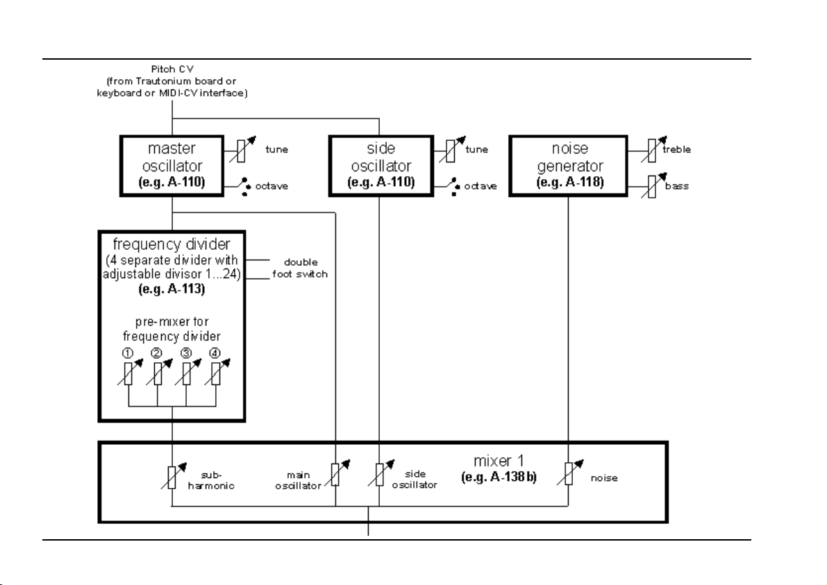
The replica of the Trautonium sound generation with
the A-100 presents itself as the A-113 contains all the
basic sound source elements of the Trautonium. The
Trautonium Format Filter A-104 completes the sound
generation as it is a copy of the lowpass/bandpass
arrangement of the Mixtur Trautonium. Only a few
A-100 standard modules (VCO, VCA, LFO, ADSR)
have to be added to obtain the typical Trautonium
sound.
Fig. 8 shows the schematic construction of the Trauto-
nium sound generation using A-100 modules.
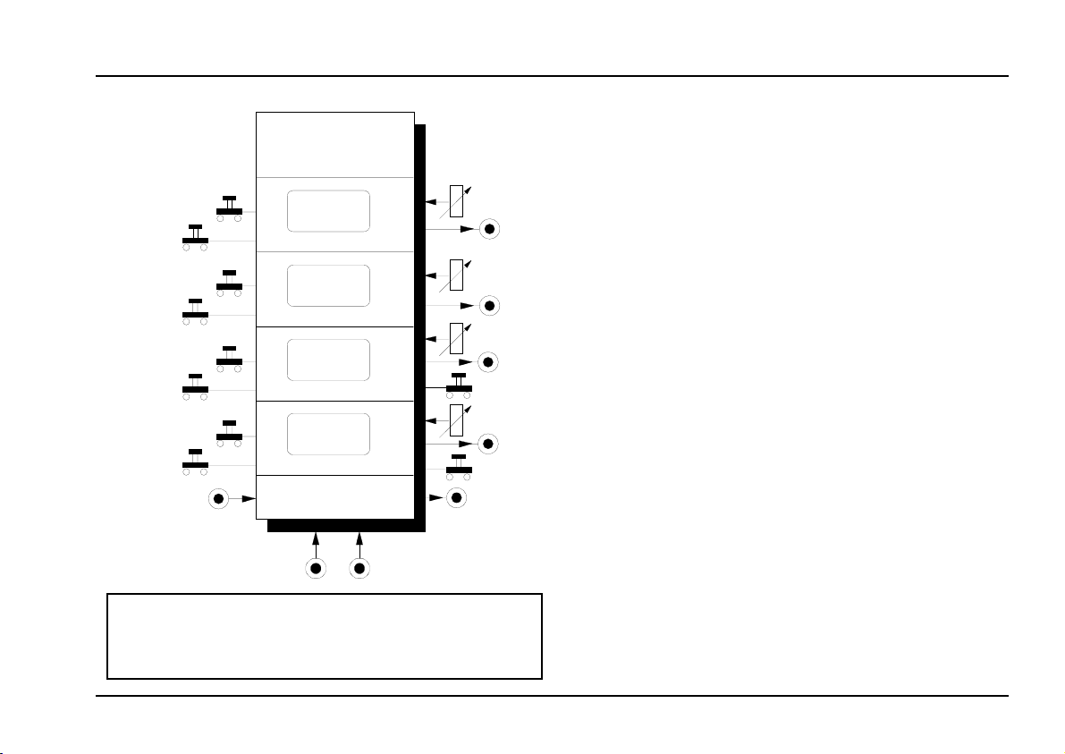
A-113 as a complex sound source
A-113 in combination with a VCO makes available a
very complex and powerful sound source for a lot of
sound experiments. The four subharmonics generated
by the A-113 contain strong harmonic spectra with
even and odd harmonics. They represent ideal basic
sound sources to be modified with separate sound
processing modules.
Fig. 9 shows an example. "XYZ" represents any sound
processing combination of modules: e.g. VCF, VCA,
Phaser, Distortion, Ring Modulator, Vocoder, Fre-
quency Shifter, Spring Reverb and so on with control-
ling modules like ADSR, LFO, Random, S&H, There-
min, Light-controlled CV, Joy Stick, MIDI interface and
so on. The controlling modules may be triggered or
synchronized (e.g. with a keyboard or sequencer con-
trolled gate) or free running.