Dolby Laboratories 131 User manual

Dolby Speaker System 131
Owner's Manual
1 January 2022
Issue 1 Part number: 8800300

Notices
Copyright
© 2022 Dolby Laboratories. All rights reserved.
Dolby Laboratories, Inc.
1275 Market Street
San Francisco, CA 94103-1410 USA
Telephone 415-558-0200
Fax 415-645-4000
http://www.dolby.com
Trademarks
Dolby and the double-D symbol are registered trademarks of Dolby Laboratories.
The following are trademarks of Dolby Laboratories:
Dialogue Intelligence™
Dolby®
Dolby Advanced Audio™
Dolby Atmos®
Dolby Audio™
Dolby Cinema®
Dolby Digital Plus™
Dolby Digital Plus Advanced Audio™
Dolby Digital Plus Home Theater™
Dolby Home Theater®
Dolby Theatre®
Dolby Vision®
Dolby Vision IQ™
Dolby Voice®
Feel Every Dimension™
Feel Every Dimension in Dolby™
Feel Every Dimension in Dolby Atmos™
MLP Lossless™
Pro Logic®
Surround EX™
All other trademarks remain the property of their respective owners.
Patents
THIS PRODUCT MAY BE PROTECTED BY PATENTS AND PENDING PATENT APPLICATIONS IN THE UNITED
STATES AND ELSEWHERE. FOR MORE INFORMATION, INCLUDING A SPECIFIC LIST OF PATENTS PROTECTING
THIS PRODUCT, PLEASE VISIT http://www.dolby.com/patents.
Product model
THIS DOCUMENTATION APPLIES TO MODEL: CID1025 and MODEL: CID1029.
Limited warranty and warranty exclusions
THE LIMITED WARRANTY AND WARRANTY EXCLUSIONS MAY BE FOUND AT THE FOLLOWING URL: https://
www.dolby.com/us/en/about/warranty-and-maintenance-policies.html
Notices
Dolby Speaker System 131 Owner's Manual 2
Issue 1 Part number: 8800300 1 January 2022

Contents
1 Important safety and regulatory information............................................................................................4
2 Introduction to Dolby Speaker System 131................................................................................................7
2.1 About this documentation....................................................................................................................8
2.2 CS131MH key features and benefits..................................................................................................... 8
2.3 CS136LF key features and benefits.......................................................................................................9
2.4 Selecting the wire for the System 131.................................................................................................. 10
2.5 Installing System 131 in a typical auditorium ..................................................................................... 11
2.6 Additional information..........................................................................................................................13
2.7 Contacting Dolby .................................................................................................................................. 13
3 Assembling System 131...............................................................................................................................14
3.1 Assembling and installing System 131................................................................................................. 15
3.2 Aiming System 131................................................................................................................................ 18
3.3 Connecting electrical components ......................................................................................................20
4 Dolby Speaker System 131 and system components specifications........................................................ 29
4.1 Dolby Speaker System 131 specifications............................................................................................30
4.2 CS131MH specifications........................................................................................................................ 31
4.3 CS136LF specifications..........................................................................................................................33
4.4 Dolby Speaker System dimensions...................................................................................................... 34
5 Dolby Speaker System 131 digital signal processing requirements......................................................... 35
5.1 System 131 triamplifier mode...............................................................................................................36
5.2 System 131 biamplifier mode............................................................................................................... 37
6 Setting system limiters................................................................................................................................40
7 Documentation revision history................................................................................................................. 42
Contents
Dolby Speaker System 131 Owner's Manual 3
Issue 1 Part number: 8800300 1 January 2022

1
Important safety and regulatory information
Safety
INSTALLER ASSUMES ALL RESPONSIBILITY AND LIABILITY FOR THE INSTALLATION OF
THIS PRODUCT.
No information contained in this guide is intended as a warranty on the part of Dolby.
Anyone using this information assumes all liability arising from its use. Product
abuse, use of the product not in accordance with Dolby instructions, or use in an
application for which the product has not been designed is not covered under any
Dolby warranty, nor is Dolby liable for any loss or damage.
Installation must be performed by qualified, licensed, and insured installers, and
installed in accordance with all laws, rules, and regulations applicable to the
installation site. Failure to do so could result in serious personal injury or even death.
Prior to installing this product, read and completely understand the installation
instructions. You must read these instructions to prevent personal injury and
property damage. Keep the installation instructions in an easily accessible location
for future reference.
A licensed professional engineer must approve the placement and method of
attachment to the building structure prior to the installation of the system.
All information presented herein is based upon materials and practices common to
North America and may not directly apply to other countries because of diering
material dimensions, specifications, and/or local regulations. Installers in other
countries should consult with appropriate engineering and regulatory authorities for
specific guidelines.
Any supplied rigging hardware is intended only for use with the specified
loudspeaker(s). The installer assumes all risk of loss and/or injury arising out of the
use of the supplied rigging hardware with any other loudspeaker. All other rigging is
considered part of the venue and/or installer-supplied equipment and is not
addressed in this guide. This guide is not a comprehensive source for rigging in
general. Installer assumes all responsibility for ensuring that accepted rigging and
safety practices are employed. Installer assumes all responsibility for the appropriate
use of Dolby supplied rigging hardware and follows at a minimum all applicable laws,
rules, and regulations in force for each venue.
Make sure that no water pipes, natural gas lines, electrical wire, or conduit are
present where the speaker is to be installed. Cutting or drilling into water pipes,
natural gas lines, electrical wire, or conduit could cause serious personal injury or
property damage.
Important safety and regulatory information
Dolby Speaker System 131 Owner's Manual 4
Issue 1 Part number: 8800300 1 January 2022

Dolby is not responsible for the application of its products for any purpose or the
misuse of this information for any purpose. Furthermore, Dolby is not responsible for
the abuse of its products caused by avoiding compliance with inspection and
maintenance procedures or any other abuse.
BKT.FLR floor brackets are available (sold separately) to secure the entire speaker
system to the auditorium mounting surface. Vibration from this type of speaker
system is high and may cause cabinets to shi. Failure to secure the bottom speaker
cabinet to the mounting surface may result in the entire system tipping or falling,
which may cause damage or injury. Proper selection of mounting hardware is not
included; proper assembly and installation of mounting hardware, including, but not
limited to, selection of appropriate weight-bearing support and bracket use, are the
exclusive responsibility of the installer. Dolby disclaims any liability, including
damage or injury, for the use of mounting hardware supplied by any party other than
Dolby. Any modification to the speaker system hardware provided by Dolby (for
example, mounting by drilling holes into the speaker system) will render the product
warranty null and void.
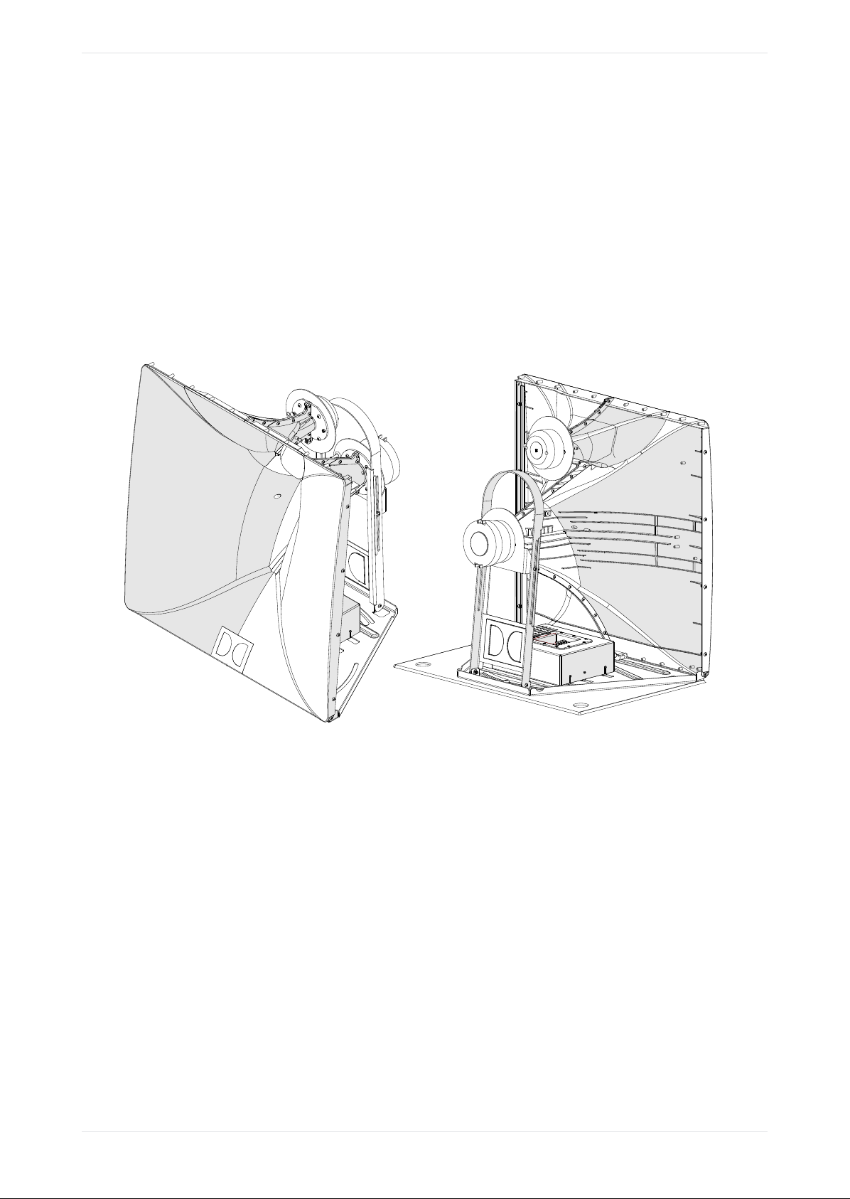
Caution: Use proper liing techniques when working with
heavy objects to avoid personal injury. Always be careful
when moving the CS136LF or the assembled Dolby Speaker
System 131 and employ at least two people when
attempting any relocation of the loudspeakers.
No open flame sources should be placed on or near the apparatus. Do not install near
any heat sources such as radiators, heat registers, stoves, or other apparatus that
produce heat.
Storage temperature: -4 to +140°F (-20 to +60°C). The products covered by this
manual are not intended for use in high-moisture environments. Moisture can
damage the product and cause corrosion of electrical contacts and metal parts. Avoid
exposing the speakers to direct moisture. Keep speakers out of extended or intense
direct sunlight. Premature product failure or serious personal injury could occur if
this product is used outdoors or in wet indoor environments.
Caution: Vibration from this type of speaker system is high
and may cause cabinets to shi. Failure to secure the bottom
speaker cabinet to the building structure may result in the
speaker system tipping or falling, which may cause damage or
injury.
High temperature warning: Loudspeaker system may reach
elevated temperatures during operation. Always remove all
drive signals and allow ample time for the system to cool
down prior to handling.
Hearing damage can occur by prolonged exposure to excessive sound pressure level (SPL); the
loudspeaker is easily capable of generating SPL suicient to cause permanent hearing damage to
performers, production crew, or audience members. Caution should be taken to avoid prolonged
exposure to SPL in excess of 90 dB.
This product is intended for indoor use only.
Clean the metal frame and chassis only with a dry cloth.
Do not block any ventilation openings. Install in accordance with the instructions as detailed in this
manual and the Product Information document.
Do not install near any heat sources, such as radiators, heat registers, stoves, or other apparatus
(including amplifiers) that produce heat.
Dolby Speaker System 131 Owner's Manual 5
Issue 1 Part number: 8800300 1 January 2022

When a rolling cart is used, use caution when moving the cart/apparatus combination to avoid injury.
Refer all servicing to qualified service personnel. Servicing is required when the apparatus has been
damaged in any way.
This product may require installation in a restricted access location. Please refer to this manual and to
the Product Information document.
Warning:
To reduce electric shock, do not expose the apparatus to dripping or splashing; no objects filled with
liquids, such as mugs, shall be placed on the apparatus.
Caution:
Troubleshooting must be performed by a trained electrician. To reduce the risk of electric shock, do
not attempt to service this equipment unless you are qualified to do so.
Caution:
This symbol that appears on the unit and/or instruction manual is intended to alert the user to the
presence of important safety operating and maintenance instructions.
Warning:
This symbol that appears on the unit and/or instruction manual is intended to alert the user to the
presence of uninsulated "dangerous" voltage within the product's enclosure that may be of suicient
magnitude to constitute a risk of electric shock to persons.
High temperature warning:
This symbol that appears on the unit and/or the instruction manual is intended to alert the user that
the item can be hot and that care must be taken accordingly.
EU environmental regulations/compliance and product disposal information
Restriction of Hazardous Substances Directive (RoHS): All Dolby products comply with the
requirements of the EU RoHS Directive. This product is electronic equipment and should be disposed
of in accordance with all applicable laws.
Do not dispose as household waste. Do not dispose of the product in a fire. Please dispose of this
product by taking it to your local electronic waste collection point or recycling center. For information
regarding where to recycle electronic equipment, contact your local dealer. For additional information
regarding Waste Electrical and Electronic Equipment (WEEE) and product disposal go to http://
www.dolby.com/us/en/about/environmental-commitment.html.
Russian environmental regulations and compliance
This product complies with Russian EAC RoHS requirements.
Important safety and regulatory information
Dolby Speaker System 131 Owner's Manual 6
Issue 1 Part number: 8800300 1 January 2022

2
Introduction to Dolby Speaker System 131
The Dolby Speaker System 131 (also referred to as System 131 in this documentation) is designed to
meet the needs of a high-performance screen speaker in a large Dolby Atmos or premium large format
cinema. System 131 delivers consistent audio coverage and uniform volume shading for every seat in a
venue of up to approximately 34 meters (111.5 feet) in depth. System 131 consists of one CS131MH
loudspeaker for mid and high frequencies and one CS136LF loudspeaker for low and low/mid
frequencies, providing greater intelligibility and enhanced low-frequency extension. With intuitive
ergonomic design and features, System 131 enables quick, easy installation and service. Built on the
foundation of the Dolby industry-leading system design and support philosophy, System 131 provides
elevated premium large format performance and streamlines speaker integration.
Figure 1: Dolby Speaker System 131 full speaker stack
This chapter covers:
•About this documentation
•CS131MH key features and benefits
•CS136LF key features and benefits
•Selecting the wire for the System 131
•Installing System 131 in a typical auditorium
•Additional information
•Contacting Dolby
Introduction to Dolby Speaker System 131
Dolby Speaker System 131 Owner's Manual 7
Issue 1 Part number: 8800300 1 January 2022

2.1 About this documentation
This documentation provides key features and benefits of System 131 and shows you how to install the
system in a typical cinematic exhibition environment.
2.2 CS131MH key features and benefits
System 131 uses one CS131MH unit, which reproduces mid- and high-frequency audio using the Dolby
patented dual-entrant waveguide (two drivers in the same horn structure) that enables close proximity of the
mid- and high-frequency drivers in the vertical plane. This configuration yields improved pattern and
amplitude control around the crossover frequency, yielding smoother full-frequency response coverage to all
seats in the auditorium.
Figure 2: CS131MH front (le) and rear (right)
• A sculpted front horn enables closer placement of the horn to the screen (even when the horn is tilted
forward), which minimizes interference from screen reflections while achieving downward angles to
cover the entire audience.
• The high-frequency driver is a very low-distortion 51 mm high-temperature polymer dome driver with a
frequency response up to 20 kHz.
• The mid-frequency driver is a unique high-performance composite diaphragm based compression driver
providing high sensitivity and power handling while covering the entire primary vocal range (400 Hz to 4
kHz), greatly enhancing intelligibility, even in the largest auditoriums.
• The advanced input plate features a high-current, spring-loaded terminal block that enables quick
installation without the need for spade lugs or a crimping tool.
• To easily select between the passive crossover or to directly amplify each driver, a unique flip-card circuit
board enables simple electrical routing and tool-free configuration.
• The entire assembly mounts directly to the CS136LF unit and features independent horizontal and
vertical aiming adjustments.
• A convenient aiming mechanism uses an installer-provided common laser pointer for accurate pointing of
the mid-/high-frequency horn to achieve maximum coverage.
• The dual-entrant asymmetrical horn enables close transducer proximity in the vertical plane, which
yields improved pattern and amplitude control around the crossover frequency.
Introduction to Dolby Speaker System 131
Dolby Speaker System 131 Owner's Manual 8
Issue 1 Part number: 8800300 1 January 2022

• The unique asymmetrical mid-/high-frequency horn design provides long-distance coverage to the back
of the cinema from the top of the horn, whereas the bottom of the horn provides wider coverage and
volume shading for the audience closer to the screen. This provides greatly improved coverage for the
entire auditorium in comparison to conventional horn designs.
Figure 3: Dolby asymmetrical horn coverage
2.3 CS136LF key features and benefits
System 131 utilizes one CS136LF unit to produce the low frequencies and low/mid frequencies.
Figure 4: CS136LF
• Contains two 15-inch woofers that can be driven in parallel, or driven individually to maximize available
amplifier power.
CS136LF key features and benefits
Dolby Speaker System 131 Owner's Manual 9
Issue 1 Part number: 8800300 1 January 2022

• Each 15-inch driver is contained in an independent chamber within the cabinet, providing improved
performance and reliability.
• On the CS136LF, the unique flip-card printed circuit board enables electrical routing for parallel wiring to
each driver from a separate amplifier channel, or individual wiring to the amplifier channel on each
driver. With the CS136LF flip card, you can select either biamplifier mode or single-amplifier mode.
• The close spacing of the woofers improves system vertical dispersion.
• Rubber feet on the bottom of the cabinet provide vibration control.
• Integrated handles on the sides of the speaker cabinet are positioned at the center of gravity to improve
safety and comfort during handling and installation.
• The optional BKT.FLR floor bracket kit (available from Dolby) enables secure installation of the entire
system to the building structure or a screen platform attached to the building structure. The kit includes
two brackets.
• The CS136LF attachment points are provided for connecting to the auditorium mounting surface only;
they are not intended for hanging or flying the speaker. Always be sure to adhere to local building codes
in your region.
• The advanced input plate features a high-current, spring-loaded terminal block, which enables quick
installation with no crimp tools or spade lugs needed, vastly simplifying installation.
2.4 Selecting the wire for the System 131
It is important that you select the correct wire gauge for the System 131.
Typically, no more than 0.5 dB (or 11%) of power should be lost in the cabling. The System 131 input plates
accept an American Wire Gauge (AWG) of 18 AWG to 6 AWG (1 mm2to 16 mm2). Typically, we recommend a
wire gauge of 16 AWG to 12 AWG (1.5 mm2 to 4 mm2).
Note: The input terminals are marked with indicators to show the polarity. Per International
Electrotechnical Commission (IEC) standards, a positive voltage on the positive marked input results
in the transducers moving outward (with the exception of the high-frequency channel in passive
mode only, which will have a negative polarity). The CS131MH and CS136LF dier in the order of
negative and positive terminations. You must verify the positive and negative markings for each
respective product. Always tie the cable down to the available hardware to minimize any buzzing or
pullouts. If possible, aer wiring is completed, play sound through the speaker to identify any
connection issues, buzzing, or rattling.
Related information
Connecting electrical components on page 20
Introduction to Dolby Speaker System 131
Dolby Speaker System 131 Owner's Manual 10
Issue 1 Part number: 8800300 1 January 2022

2.5 Installing System 131 in a typical auditorium
In a typical auditorium, System 131 is installed behind the screen, with the acoustic center of the speaker
located two-thirds of the distance from the bottom of the screen.
The following figure shows the placement of the speaker behind the screen, as indicated in the Dolby Atmos
Specifications. To position the speakers at the correct height, you should build a platform and attach it to the
building structure.
To improve localization and smooth pan-throughs, larger cinemas can benefit by adding le-center and
right-center screen speakers.
Figure 5: Typical auditorium installation
The following figure shows the exact placement of the System 131 acoustic center. The elevation of the
platform (attached to the building structure) that secures the speaker should be located with the acoustic
center of the horn positioned exactly two-thirds the distance from the bottom to the top of the screen. The
acoustic center of the speaker is 1.420 meters (55.90 inches) above the platform.
Figure 6: System 131 acoustic center
System 131 is designed to be placed as close to the screen surface as possible with a minimum distance of
5-7 cm. This minimizes high-frequency reflections (screen loss) and reduces airflow disturbances on the
screen surface. When aiming the system, the CS131MH alignment may require that the entire system be set
back from the screen to accommodate proper tilting and aiming. If you are unsure of the angle needed for
the CS131MH, it may be advisable to temporarily place the CS131MH onto the screen-frame platform that is
attached to the building structure and perform a rough vertical and horizontal aiming, which can help you
determine the placement of the entire system.
Installing System 131 in a typical auditorium
Dolby Speaker System 131 Owner's Manual 11
Issue 1 Part number: 8800300 1 January 2022

Figure 7: System 131 screen planes
.GLL format files for soware simulation modeling
There are .GLL files for the CS131MH and CS136LF that you can use to simulate System 131 in acoustical
simulation soware. You can download the .GLL files at https//:www.dolby.com/us/en/professional/
cinema/products/sys131.html. To run the .GLL files, use EASE or EASE Focus soware. EASE Focus soware
is free and can be downloaded from https://focus.afmg.eu/index.php/fc-downloads-en.html.
Following are descriptions of the System 131 .GLL files:
•CS136LF for Screen Channel System 131
To create the System 131 screen channel, the loudspeaker entry point into the simulation is at the bottom
of the loudspeaker.
For correct simulation, place the LF height entry point (z axis) at the platform height in the auditorium. To
create System 131, the CS131MH mid/high loudspeaker must be located 1.42 meters (4.66 feet) above this
same point for correct placement on top of the CS136LF.
•.CS131MH GLL
To finish creating the System 131 screen channel, add the CS131MH. The loudspeaker entry point into the
simulation is at the acoustic center of the system.
Place the height entry point (z axis) of the CS131MH at 1.42 meters (4.66 feet) above the height entry
point of the CS136LF .GLL. The x and y axes should match the companion CS136LF.
Introduction to Dolby Speaker System 131
Dolby Speaker System 131 Owner's Manual 12
Issue 1 Part number: 8800300 1 January 2022

The CS131MH .GLL files can then pan horizontally ±20 degrees, and tilt +15/-20 degrees, independent of
the CS136LF, as it would in a typical configuration.
Figure 8: System 131 vertical down tilt
Related information
System 131 and system components specifications
2.6 Additional information
Additional information regarding System 131 is provided.
• System weight is approximately 96.2 kg (212 lb).
• System 131 is switchable between triamplifier mode or biamplifier mode. We recommend triamplifier
mode for maximum performance.
• Amplifier selection is aided by additional data, as specified in the System 131 and system components
specifications. (See the link at the end of this section.)
• The power-draw specification provides the actual power draw in watts at the rated Vrms in the design,
instead of calculated power. This can aid in optimizing amplifier power budgets, as the measured power
is almost always lower than calculated power (sometimes significantly).
• The maximum voltage peak specification is useful for selecting an amplifier that has a voltage rail at or
above the rating for the loudspeaker maximum dynamic performance. Some amplifier companies
provide this data in their respective technical data sheets (or provide the data by request).
• Wire gauge selection should always use industry-standard practice based on the loudspeaker rated ohms
and cable length. Typical maximum acceptable power loss is 0.5 dB, or less than 11%.
2.7 Contacting Dolby
You can contact Dolby Cinema Solutions and Support using email or regional telephone numbers. You can
also access documentation by visiting the Dolby customer portal.
Contact Dolby Cinema Solutions and Support
• Send an email to cinemasupport@dolby.com.
• Call:
AMERICAS: +1-415-645-4900
ASIA, CHINA, and PACIFIC RIM: +86-10-800-320-0128
EMEA: +44-33-0808-7700
JAPAN: +81-3-4520-9798
Access documentation
Visit https://customer.dolby.com.
Submit feedback about this documentation
Send an email to documentation@dolby.com.
Additional information
Dolby Speaker System 131 Owner's Manual 13
Issue 1 Part number: 8800300 1 January 2022

3
Assembling System 131
Note: BKT.FLR floor brackets are available from Dolby (sold separately) to secure the
speaker system to the building structure. When using the BKT.FLR brackets, the installer
must supply the mounting hardware necessary to secure the speaker system to the
building structure. The holes in the bracket are sized for M10 or 3/8-inch bolts.
Caution: Vibration from this type of speaker system is high and may cause cabinets to
shi. Failure to secure the bottom speaker cabinet to the building structure may result in
the system tipping or falling, which may cause damage or injury.
Caution: Dolby disclaims any liability, including damage or injury, for the use of
mounting hardware, supports, and brackets not provided by Dolby. Any modification to
the speaker system (for example, mounting by drilling holes into the speaker system) will
render the product warranty null and void.
The following sections provide instructions on how to assemble and install System 131.
•Assembling and installing System 131
•Aiming System 131
•Connecting electrical components
Assembling System 131
Dolby Speaker System 131 Owner's Manual 14
Issue 1 Part number: 8800300 1 January 2022

3.1 Assembling and installing System 131
Instructions are provided to set up a Dolby System 131 speaker system.
About this task
You need these parts and tools:
• Installer-provided 6 mm hex driver.
• Installer-provided 4 mm hex driver for vertical aiming.
• BKT.FLR brackets or angle brackets not supplied by Dolby (optional, but recommended). The two BKT.FLR
brackets are available in a separate Dolby kit to secure the speaker stack to the auditorium building
structure platform. When using the BKT.FLR brackets, you need screws, washers, and other components
to attach the speaker stack to the platform that is attached to the building structure. The holes in the
bracket are sized for M10 or 3/8-inch bolts. (To connect the bracket to the CS136LF, repurpose the speaker
M10 bolts and use the washers included in the BKT.FLR package.)
• Installer-provided laser pointer to help with aiming the CS131MH.
• Installer-provided serviceable thread-locking compound (recommended).
• Installer-provided acoustic or nonhardening caulking (recommended).
To perform this task safely:
Caution: BKT.FLR floor brackets are available from Dolby (sold separately) to secure the entire
speaker system to a platform that is attached to the building structure. Vibration from this type of
speaker system is high and may cause the cabinets to shi. Failure to secure the bottom speaker
cabinet to the platform attached to the building structure may result in the entire system tipping or
falling, which may cause damage or injury. Proper selection of mounting hardware is not included;
proper assembly and installation of mounting hardware, including, but not limited to, selection of
appropriate weight bearing support and bracket use, are the exclusive responsibility of the installer.
Dolby disclaims any liability, including damage or injury, for the selection of mounting hardware not
manufactured by Dolby and previously approved in writing by Dolby, and/or bracket installation not
installed by Dolby. Any modification to the speaker system hardware provided by Dolby (such as
mounting by drilling holes into the speaker system) will render the product warranty null and void.
Securing the low-frequency cabinet
Procedure
1. Once you determine the proper placement of the system relative to the screen, secure System 131 to the
building structure, using a platform on the screen frame. For this purpose, we recommend the use of the
BKT.FLR brackets or equivalent brackets not. Check with local building codes, and always refer the
installation to a qualified professional.
2. Remove the four M10 bolts from the sides of the CS136LF speaker cabinet, as shown in the following
figure.
3. Reinstall these bolts with the BKT.FLR brackets (or equivalent), using the included M10 washers
(packaged with BKT.FLR) or hardware not provided by Dolby, and then retighten. You must supply the
bolts to secure the bracket to the mounting surface. We recommend using a serviceable thread-locking
compound (for example, Loctite 243). We also recommend applying acoustic or other nonhardening
caulking to the bottom side of the bracket to isolate vibration from the speaker to the platform that is
attached to the building structure. Install all fasteners back into their threaded inserts to prevent air leaks.
Note: Proper selection and installation of mounting hardware is the exclusive responsibility of the
installer. We recommend using M10 bolts and a serviceable thread-locking compound (for
example, Loctite 243). We also recommend applying acoustic or other nonhardening caulking to
the bottom side of the bracket to isolate speaker vibration from the building structure.
Assembling and installing System 131
Dolby Speaker System 131 Owner's Manual 15
Issue 1 Part number: 8800300 1 January 2022

Caution: Vibration from this type of speaker system is high and may cause cabinets to shi.
Failure to secure the bottom speaker cabinet to the building structure may result in the speaker
system tipping or falling, which may cause damage or injury.
Caution: Dolby disclaims any liability, including damage or injury, for the use of mounting
hardware, supports, and brackets not supplied by Dolby. Any modification to the speaker system
(for example, mounting by drilling holes into the speaker system) will render the product warranty
null and void.
Attention: The System 131 was designed to be placed as close to the screen as possible, within
5-7 cm. When aiming the system, angling of the CS136MH may require that the speaker system be
set back from the screen to accommodate proper tilting and aiming
Figure 9: System 131
Installer supplied
Installer supplied
BKT.FLR
fasteners
fasteners
Floor bracket
Assembling System 131
Dolby Speaker System 131 Owner's Manual 16
Issue 1 Part number: 8800300 1 January 2022

Installing the CS131MH onto the CS136LF low-frequency cabinet
1. Remove the four M10 bolts from the top CS136LF cabinet. Add four washers from the CS131MH
hardware kit.
2. Place the CS131MH cabinet on top of the CS136LF cabinet, and then reinstall the four M10 bolts and
washers through the bottom plate. We recommend a serviceable thread-locking compound (for example,
Loctite 243). Do not fully tighten the bolts until aiming is completed.
Figure 10: Mount mid/high speaker to low-frequency cabinet
Figure 11: CS131MH overhead view
Mounting screws
Tracks allowing
horn to be rotated
(under horn)
Assembling and installing System 131
Dolby Speaker System 131 Owner's Manual 17
Issue 1 Part number: 8800300 1 January 2022

3.2 Aiming System 131
It is important to aim System 131 for precise sound distribution.
About this task
Illuminate a typical aiming point that is located two-thirds back and centered in the auditorium seating area
using the laser-pointer placement shelf. To aim the system, you can use any type of laser pointer, as long as
the beam shines through the hole in the CS131MH horn and the laser body is parallel to the shelf. We
recommend a round laser pointer with a diameter between 12 mm (0.47 inches) and 21 mm (0.83 inches) or a
square laser pointer with a 12-21 mm flat-to-flat dimension.
Figure 12: Aiming for the reference listening position overhead view
Figure 13: Placing the laser
Laser pointer
placement location
Assembling System 131
Dolby Speaker System 131 Owner's Manual 18
Issue 1 Part number: 8800300 1 January 2022

Procedure
1. Once the System 131 is assembled, adjust the horizontal axis of the speaker by rotating the CS131MH on
the cabinet. The angle adjustment range is ±20 degrees from the center, as shown on the provided decal
stickers.
Figure 14: Adjust the CS131MH horizontal axis
Mounting screws
Tracks allowing
horn to be rotated
(under horn)
2. Tighten the bolts so that the horizontal adjustment is locked to 12 Nm (8.9 -lb, 106 in-lb).
3. Loosen the vertical angle adjustment points, as shown in the following figure, and tilt the horn down. The
angle adjustment range is +15/-20 degrees.
Figure 15: Loosen the vertical adjustment points
Adjust vertical
(4 mm hex driver)
Adjust vertical
(4 mm hex driver)
4. Tighten the vertical aiming screws and bottom-front pivot screws to 5.5 Nm (4.1 -lb, 49 in-lb) to lock in
this angle.
Aiming System 131
Dolby Speaker System 131 Owner's Manual 19
Issue 1 Part number: 8800300 1 January 2022

Figure 16: Aiming for the reference listening position/overhead view)
5. Aer aiming is completed, you can use the provided decal stickers if you want to cover the two laser
pointer openings. These decals are for aesthetic purposes only and do not aect system performance.
Figure 17: Hide two openings with decals
Decal placement for concealing aiming point
aperture in midrange horn
3.3 Connecting electrical components
To be sure that the speakers work correctly, you must connect all electrical components properly.
Connecting audio
Required tool: Wire stripper
Caution: Turn o all amplifiers when connecting loudspeaker wiring.
The System 131 connectors accept an American Wire Gauge (AWG) of 18 AWG to 6 AWG (1 mm2to 16 mm2).
Typically, a wire gauge of 16 AWG to 12 AWG is recommended (1.5 mm2to 4 mm2).
Assembling System 131
Dolby Speaker System 131 Owner's Manual 20
Issue 1 Part number: 8800300 1 January 2022
Table of contents
Other Dolby Laboratories Speakers System manuals