Dolby Laboratories 136 User manual

Dolby Speaker System 136 Owner’s Manual
16 December 2020
Issue 1: Part number 8800255

Notices
Copyright
© 2020 Dolby Laboratories. All rights reserved.
Dolby Laboratories, Inc.
1275 Market Street
San Francisco, CA 94103-1410 USA
Telephone 415-558-0200
Fax 415-645-4000
http://www.dolby.com
Trademarks
Dolby and the double-D symbol are registered trademarks of Dolby Laboratories.
The following are trademarks of Dolby Laboratories:
Dialogue Intelligence™
Dolby®
Dolby Advanced Audio™
Dolby Atmos®
Dolby Audio™
Dolby Cinema®
Dolby Digital Plus™
Dolby Digital Plus Advanced Audio™
Dolby Digital Plus Home Theater™
Dolby Home Theater®
Dolby Theatre®
Dolby Vision®
Dolby Vision IQ™
Dolby Voice®
Feel Every Dimension™
Feel Every Dimension in Dolby™
Feel Every Dimension in Dolby Atmos™
MLP Lossless™
Pro Logic®
Surround EX™
All other trademarks remain the property of their respective owners.
Patents
THIS PRODUCT MAY BE PROTECTED BY PATENTS AND PENDING PATENT APPLICATIONS IN THE UNITED
STATES AND ELSEWHERE. FOR MORE INFORMATION, INCLUDING A SPECIFIC LIST OF PATENTS PROTECTING
THIS PRODUCT, PLEASE VISIT http://www.dolby.com/patents.
Product model
THIS DOCUMENTATION APPLIES TO MODEL: CID1024 and MODEL: CID1025.
Limited warranty and warranty exclusions
THE LIMITED WARRANTY AND WARRANTY EXCLUSIONS MAY BE FOUND AT THE FOLLOWING URL: https://
www.dolby.com/us/en/about/warranty-and-maintenance-policies.html
Notices
Dolby Speaker System 136 Owner’s Manual Issue 1: Part number 8800255 2
16 December 2020

Contents
1 Important safety and regulatory information.................................................................................. 4
2 Introduction to Dolby Speaker System 136 ......................................................................................7
2.1 About this documentation.............................................................................................................................8
2.2 CS136MH key features and benefits.............................................................................................................. 8
2.3 CS136LF key features and benefits................................................................................................................9
2.4 Selecting the wire......................................................................................................................................... 10
2.5 Contacting Dolby ......................................................................................................................................... 10
3 Assembling System 136................................................................................................................ 12
3.1 Installing System 136 in a typical auditorium ............................................................................................13
3.2 Assembling and Installing System 136........................................................................................................16
3.3 Aiming System 136....................................................................................................................................... 19
3.4 Connecting electrical components .............................................................................................................22
4 System 136 and system components specifications........................................................................ 30
5 System 136 digital signal processing requirements.........................................................................35
6 Setting system limiters.................................................................................................................37
Contents
Dolby Speaker System 136 Owner’s Manual Issue 1: Part number 8800255 3
16 December 2020

1
Important safety and regulatory
information
Safety
INSTALLER ASSUMES ALL RESPONSIBILITY AND LIABILITY FOR THE INSTALLATION OF
THIS PRODUCT.
No information contained in this guide is intended as a warranty on the part of
Dolby. Anyone using this information assumes all liability arising from its use.
Product abuse, use of the product not in accordance with Dolby instructions, or use
in an application for which the product has not been designed is not covered under
any Dolby warranty, nor is Dolby liable for any loss or damage.
Installation must be performed by qualified, licensed, and insured installers, and
installed in accordance with all laws, rules, and regulations applicable to the
installation site. Failure to do so could result in serious personal injury or even death.
Prior to installing this product, read and completely understand the installation
instructions. You must read these instructions to prevent personal injury and
property damage. Keep the installation instructions in an easily accessible location
for future reference.
A licensed professional engineer must approve the placement and method of
attachment to the building structure prior to the installation of the system.
All information presented herein is based upon materials and practices common to
North America and may not directly apply to other countries because of differing
material dimensions, specifications, and/or local regulations. Installers in other
countries should consult with appropriate engineering and regulatory authorities for
specific guidelines.
Any supplied rigging hardware is intended only for use with the specified
loudspeaker(s). The installer assumes all risk of loss and/or injury arising out of the
use of the supplied rigging hardware with any other loudspeaker. All other rigging is
considered part of the venue and/or installer-supplied equipment and is not
addressed in this guide. This guide is not a comprehensive source for rigging in
general. Installer assumes all responsibility for ensuring that accepted rigging and
safety practices are employed. Installer assumes all responsibility for the appropriate
use of Dolby supplied rigging hardware and follows at a minimum all applicable
laws, rules, and regulations in force for each venue.
Important safety and regulatory information
Dolby Speaker System 136 Owner’s Manual Issue 1: Part number 8800255 4
16 December 2020

For Dolby Cinema theatres only: If your installation is deemed to require the use of
safety cables by Dolby or a certified engineer, refer to the information in the
Dolby
System 136 Additional Safety Cable Installation Requirements
document, which is
available from your Dolby Cinema technical representative.
Make sure that no water pipes, natural gas lines, electrical wire, or conduit are
present where the speaker is to be installed. Cutting or drilling into water pipes,
natural gas lines, electrical wire, or conduit could cause serious personal injury or
property damage.
Dolby is not responsible for the application of its products for any purpose or the
misuse of this information for any purpose. Furthermore, Dolby is not responsible for
the abuse of its products caused by avoiding compliance with inspection and
maintenance procedures or any other abuse.
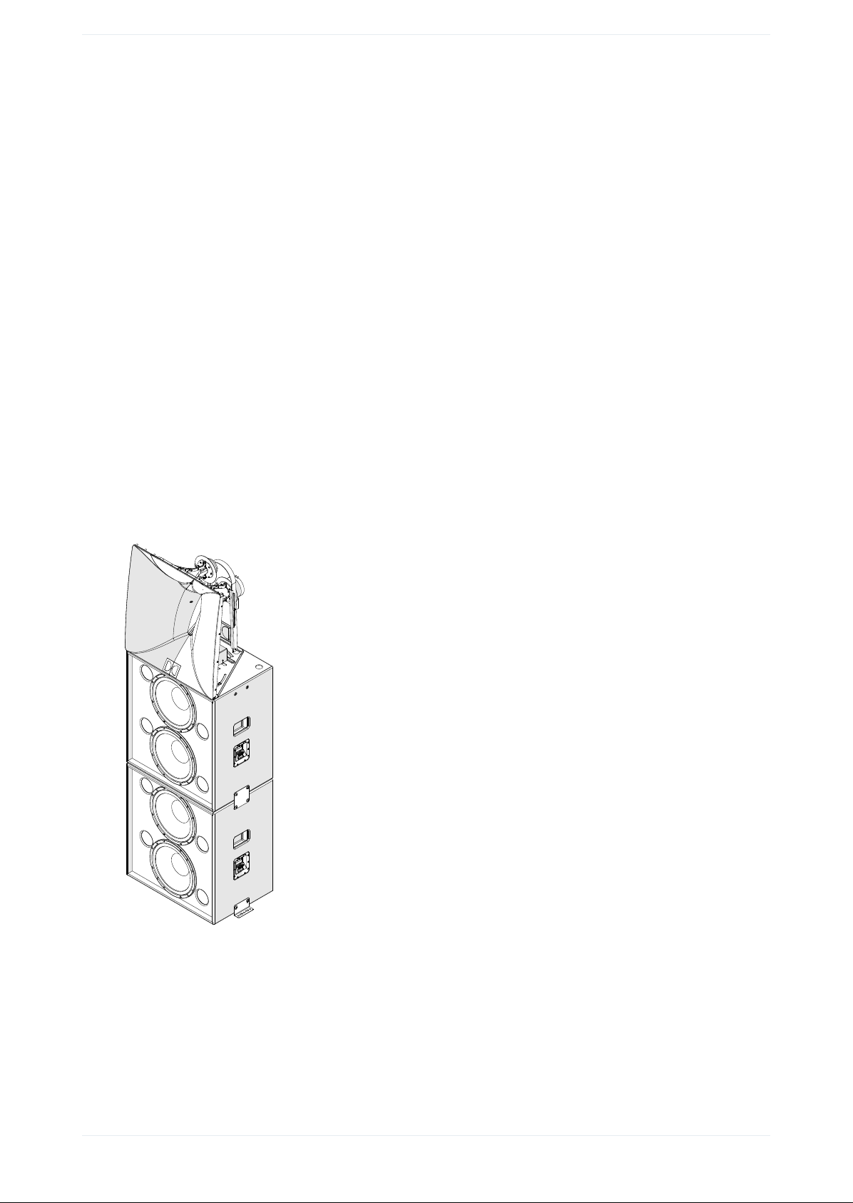
BKT.136 tie (coupling) plates (included with CS136MH) are used to connect the two
CS136LF speakers together to prevent movement or shifting of the cabinets due to
vibration from high levels of sound. These brackets must be installed prior to system
use. Dolby disclaims any liability, including damages or injury, if installer fails to
comply with these instructions.
BKT.FLR floor brackets are available (sold separately) to secure the entire speaker
system to the auditorium mounting surface. Vibration from this type of speaker
system is high and may cause cabinets to shift. Failure to secure the bottom speaker
cabinet to the mounting surface may result in the entire system tipping or falling,
which may cause damage or injury. Proper selection of mounting hardware is not
included; proper assembly and installation of mounting hardware, including, but not
limited to, selection of appropriate weight-bearing support and bracket use, are the
exclusive responsibility of the installer. Dolby disclaims any liability, including
damage or injury, for the selection of i) non-Dolby manufactured mounting hardware
or ii) third-party manufactured mounting hardware not previously approved in
writing by Dolby, and/or third-party bracket installation. Any modification to the
speaker system hardware provided by Dolby (for example, mounting by drilling holes
into the speaker system) will render the product warranty null and void.
Use proper lifting techniques when working with heavy objects to avoid personal
injury.
No open flame sources should be placed on or near the apparatus. Do not install
near any heat sources such as radiators, heat registers, stoves, or other apparatus
that produce heat.
Storage temperature: -4 to +140°F (-20 to +60°C). The products covered by this
manual are not intended for use in high-moisture environments. Moisture can
damage the product and cause corrosion of electrical contacts and metal parts.
Avoid exposing the speakers to direct moisture. Keep speakers out of extended or
intense direct sunlight. Premature product failure or serious personal injury could
occur if this product is used outdoors or in wet indoor environments.
Hearing damage can occur by prolonged exposure to excessive sound pressure level
(SPL); the loudspeaker is easily capable of generating SPL sufficient to cause
permanent hearing damage to performers, production crew, or audience members.
Caution should be taken to avoid prolonged exposure to SPL in excess of 90 dB.
Dolby Speaker System 136 Owner’s Manual Issue 1: Part number 8800255 5
16 December 2020

EU environmental regulations/compliance and product disposal information
Restriction of Hazardous Substances Directive (RoHS): All Dolby products comply with the
requirements of the EU RoHS Directive. This product is electronic equipment and should be disposed
of in accordance with all applicable laws.
Do not dispose as household waste. Do not dispose of the product in a fire. Please dispose of this
product by taking it to your local electronic waste collection point or recycling center. For information
regarding where to recycle electronic equipment, contact your local dealer. For additional information
regarding Waste Electrical and Electronic Equipment (WEEE) and product disposal go to http://
www.dolby.com/us/en/about/environmental-commitment.html.
Russian environmental regulations and compliance
This product complies with Russian EAC RoHS requirements.
Important safety and regulatory information
Dolby Speaker System 136 Owner’s Manual Issue 1: Part number 8800255 6
16 December 2020

2
Introduction to Dolby Speaker System 136
The Dolby Speaker System 136 is designed to meet the needs of a high-performance screen speaker in
a large Dolby Atmos or premium large format (PLF) cinema. System 136 delivers consistent audio
coverage and uniform volume shading for every seat in the venue up to approximately 165 feet (50.3
meters) in depth. The Dolby System 136 consists of one CS136MH loudspeaker for mid and high
frequencies and two CS136LF loudspeakers for low and low/mid frequencies, providing greater
intelligibility and enhanced low-frequency extension. With intuitive ergonomic design and features,
Dolby System 136 enables quick, easy installation and service. Built on the foundation of the Dolby
industry-leading system design and support philosophy, Dolby System 136 provides elevated
premium large format (PLF) performance and streamlines speaker integration. These components are
coupled together to create a screen speaker system that provides better audience coverage, lower
distortion (discomfort), and increased low-frequency response.
Figure 1: System 136 full speaker stack
•About this documentation
•CS136MH key features and benefits
•CS136LF key features and benefits
•Selecting the wire
•Contacting Dolby
Dolby Speaker System 136 Owner’s Manual Issue 1: Part number 8800255 7
16 December 2020

2.1 About this documentation
This documentation shows you how to install a Dolby Speaker System 136.
2.2 CS136MH key features and benefits
Dolby Speaker System 136 uses one CS136MH unit, which reproduces mid- and high-frequency audio using a
dual-entrant horn (two drivers in the same horn structure) that enables close proximity of the mid- and high-
frequency drivers in the vertical plane. This configuration yields improved pattern and amplitude control
around the crossover frequency, yielding smoother full-frequency response coverage to all seats in the
auditorium.
Figure 2: CS136MH front (left) and rear (right)
• A sculpted front horn enables closer placement of the horn to the screen (even when the horn is tilted
forward), which minimizes interference from screen reflections while achieving downward angles to
cover the entire audience.
• The high-frequency driver is a very low-distortion 75 mm titanium dome driver with a frequency response
up to 20 kHz.
• The mid-frequency driver is a specially designed ring-radiator compression driver providing high
sensitivity and power handling while covering the entire primary vocal range (400 Hz to 4 kHz), greatly
enhancing intelligibility, even in the largest auditoriums.
• The advanced input plate features a high-current, spring-loaded terminal block that enables quick
installation without the need for spade lugs or a crimping tool.
• To easily select a passive crossover or directly amplify each driver, a unique flip-card circuit board
enables simple electrical routing and tool-free configuration.
• The entire assembly mounts directly to the CS136LF unit and features independent horizontal and
vertical aiming adjustments.
• A convenient aiming mechanism uses a common laser pointer for accurate pointing of the mid/high
frequency horn to achieve maximum coverage.
• The dual-entrant asymmetrical horn enables close transducer proximity in the vertical plane, which
yields improved pattern and amplitude control around the crossover frequency.
Introduction to Dolby Speaker System 136
Dolby Speaker System 136 Owner’s Manual Issue 1: Part number 8800255 8
16 December 2020

• The unique asymmetrical mid-/high-frequency horn design provides long-distance coverage to the back
of the cinema from the top of the horn, while the bottom of the horn provides wider coverage and
volume shading for the audience closer to the screen. This provides greatly improved coverage for the
entire auditorium in comparison to conventional horn designs.
Figure 3: Dolby asymmetrical horn coverage
2.3 CS136LF key features and benefits
Dolby Speaker System 136 utilizes two CS136LF units to produce the low frequencies and low/mid
frequencies. Each cabinet receives differently processed audio.
Figure 4: CS136LF two units stacked
CS136LF key features and benefits
Dolby Speaker System 136 Owner’s Manual Issue 1: Part number 8800255 9
16 December 2020

• Each unit contains two 15-inch woofers that can be driven in parallel, or driven individually to maximize
available amplifier power.
• Each 15-inch driver is contained in an independent chamber within the cabinet that provides improved
performance and reliability.
• On the CS136LF, the unique flip-card printed circuit board enables electrical routing for parallel wiring of
the drivers powered from a single amplifier channel, or individual wiring to the amplifier channel on each
driver. With the CS136LF flip card, you can select either bi-amplifier mode or single-amplifier mode.
• The close spacing of the woofers combined with the individual processing of each cabinet improves
system vertical dispersion.
• Rubber feet on the bottom of each cabinet align with recesses on the top that help align stacked cabinets
and provide overall vibration control.
• Integrated handles on the sides of the speaker cabinet are positioned at the center of gravity to improve
safety and comfort during handling and installation.
• Included tie plates couple two CS136LF cabinets together safely and securely.
• Optional BKT.FLR floor brackets (available from Dolby) enable secure installation of the entire system to
the building structure or a screen platform attached to the building structure. The attachment points are
for stacking only; they are not intended for hanging or flying. Always be sure to adhere to local building
codes in your region.
• The advanced input plate features a high-current, spring-loaded terminal block, which enables quick
installation with no crimp tools or spade lugs needed, vastly simplifying installation.
2.4 Selecting the wire
This section can assist you in selecting the correct wire gauge.
Typically, no more than 0.5 dB ( or 11%) of power should be lost in the cabling. The System 136 input plates
accept an American wire gauge (AWG) of 18 AWG to 6 AWG.
Note: The input terminals are marked with indicators to show the polarity. Per International
Electrotechnical Commission (IEC) standards, a positive voltage on the positive marked input results
in the transducers moving outward (with the exception of the high-frequency channel in passive
mode only, which will have a negative polarity). The CS136MH and CS136LF differ in the order of
negative and positive terminations. You must verify the positive and negative markings for each
respective product. Always tie the cable down to the available hardware to minimize any buzzing or
pullouts. If possible, after wiring is completed, play sound through the speaker to identify any
connection issues, buzzing, or rattling.
Related information
Connecting electrical components on page 22
2.5 Contacting Dolby
You can contact Dolby Cinema Solutions and Support using email or regional telephone numbers. You can
also access documentation by visiting the Dolby customer portal.
Contact Dolby Cinema Solutions and Support
• Send an email to [email protected].
• Call:
Americas: +1-415-645-4900
Europe/Middle East/Africa (EMEA): +44-33-0808-7700
Asia-Pacific (APAC): +86-400-692-6780
Japan: +81-3-4540-6782
Introduction to Dolby Speaker System 136
Dolby Speaker System 136 Owner’s Manual Issue 1: Part number 8800255 10
16 December 2020

Access documentation
Visit https://customer.dolby.com.
Submit feedback about this documentation
Send an email to [email protected].
Contacting Dolby
Dolby Speaker System 136 Owner’s Manual Issue 1: Part number 8800255 11
16 December 2020

3
Assembling System 136
The following sections provide instructions on how to assemble and install System 136.
•Installing System 136 in a typical auditorium
•Assembling and Installing System 136
•Aiming System 136
•Connecting electrical components
Assembling System 136
Dolby Speaker System 136 Owner’s Manual Issue 1: Part number 8800255 12
16 December 2020

3.1 Installing System 136 in a typical auditorium
In a typical auditorium, System 136 is installed behind the screen, with the acoustic center of the speaker
located two-thirds of the distance from the bottom of the screen.
The following figure shows the placement of the speaker behind the screen, as indicated in the Dolby Atmos
Specifications. To position the speakers at the correct height, you should build a platform and attach it to
the building structure.
To improve localization and smooth pan-throughs, larger cinemas can benefit by adding left-center and
right-center screen speakers.
Figure 5: Typical auditorium installation
2/3 Screen
Height
Left Left Center Right Center Right
2.39:1 1.85:1
C
L
Center
The following figure shows the exact placement of the System 136 acoustic center. The elevation of the
platform (attached to the building structure) that secures the speaker stack should be located with the
acoustic center of the horn positioned exactly two-thirds the distance from the bottom of the screen. The
acoustic center of the speaker is 2.27 meters (89.2 inches) above the platform.
Figure 6: System 136 acoustic center
89.22
2.27 m
Acoustic center
Installing System 136 in a typical auditorium
Dolby Speaker System 136 Owner’s Manual Issue 1: Part number 8800255 13
16 December 2020

System 136 is designed to be placed as close to the screen surface as possible within 5-7 cm. When aiming
the system, angling of the CS136MH may require that the entire system be set back from the screen to
accommodate proper tilting and aiming. If you are unsure of the angle needed for the CS136MH, it may be
advisable to temporarily place the CS136MH onto the screen frame platform that is attached to the building
structure and perform a rough vertical and horizontal aiming, which can help you determine the placement
of the entire system.
Figure 7: System 136 screen planes
Screen
[2.68 in]
68 mm
Recommended distance from front
of CS136LF cabinet to rear surface
of screen for level or tilted-up
CS136MH with no side panning
0º Pan [Straight]
0º Tilt [Level]
0º Pan [Straight]
20 º Down [Max]
20 º Pan [Max]
20 º D own [Max]
Screen Screen
[10.20 in]
259 mm
Recommended distance from front
of CS136LF cabinet to rear surface
of screen to allow for maximum
down tilt of CS136MH
[14.57 in]
370 mm
Recommended distance from front
of CS136LF cabinet to rear surface
of screen to allow for maximum
down tilt and side pan of CS136MH
[12.22 in]
310 mm
20 º
[7.84 in]
199 mm
GLL format files for software simulation modeling
There are .GLL files that you can use to simulate System 136 for the CS136MH and a CS136LF double stack.
You can download the .GLL files at https://www.dolby.com/us/en/professional/cinema/products/
sys136.html. To run the .GLL files, use EASE or EASE Focus software. EASE Focus software is free, and can be
downloaded from https://focus.afmg.eu/index.php/fc-downloads-en.html.
Following are descriptions of the System 136 .GLL files:
•CS136MH GLL
To create the Dolby System 136 screen channel. The loudspeaker entry point into the simulation is at the
acoustic center of the system.
For correct simulation of System 136, place the height entry point (z axis) of the CS136MH at 2.27 m (7.45
ft) above the height entry point of the CS136LF double stack .GLL. The x and y axes should match the
companion CS136LF double stack.
Assembling System 136
Dolby Speaker System 136 Owner’s Manual Issue 1: Part number 8800255 14
16 December 2020

•CS136LF for Screen Channel System 136
To create the System 136 screen channel. The loudspeaker entry point into the simulation is at the
bottom of the stack.
For correct simulation, place the LF stack height entry point (z axis) at the platform height in the
auditorium. To create System 136, the CS136MH mid/high loudspeaker must be located 2.27 m (7.45 ft)
above this same point for correct placement on top of the stack. The CS136MH .GLL files can then pan
+/-20 degrees, and tilt +15/-20 degrees, independent of the CS136LF stack, as it would in a typical
configuration.
Figure 8: System 136 vertical down-tilt and proximity to screen
System 136 additional information
• System weight for platform stability calculations is approximately 166 kg (366 lb).
• The CS136MH is switchable between bi-amp mode or passive mode (where one amplifier channel is used
to drive both transducers). We recommend bi-amp mode for maximum performance.
• Amplifier selection is aided by additional data, as specified in the System 136 and system components
specifications.
• The power-draw specification provides the actual power draw in watts at the rated Vrms in the design,
instead of calculated power. This can aid in optimizing amplifier power budgets, as the measured power
is almost always lower than calculated power (sometimes significantly).
• The maximum voltage peak specification is useful for selecting an amplifier that has a voltage rail at or
above the rating for the loudspeaker maximum dynamic performance. Some amplifier companies
provide this data in their respective technical data sheets (or provide the data by request).
• Wire gauge selection should always use industry-standard practice based on the loudspeaker rated
ohms and cable length. Typical maximum acceptable power loss is 0.5 dB, or less than 11%.
Related information
System 136 and system components specifications on page 30
Installing System 136 in a typical auditorium
Dolby Speaker System 136 Owner’s Manual Issue 1: Part number 8800255 15
16 December 2020

3.2 Assembling and Installing System 136
This section shows you how to set up a Dolby System 136 speaker system.
About this task
You need these parts and tools:
• 6 mm hex driver.
• BKT.136 (two tie (coupling) plates provided in the CS136MH packing kit.
• BKT.FLR brackets or third-party angle bracket (optional, but recommended). When using the BKT.FLR
brackets, you need screws, washers, and other components to connect to the speaker platform that is
attached to the building structure. The holes in the bracket are sized for M10 or 3/8-inch bolts.
• Serviceable thread-locking compound (optional).
• Acoustic or nonhardening caulking (optional).
To perform this task safely:
CAUTION: BKT.FLR floor brackets are available from Dolby (sold separately) to secure the entire
speaker system to a platform that is attached to the building structure. Vibration from this type of
speaker system is high and may cause the cabinets to shift. Failure to secure the bottom speaker
cabinet to the platform attached to the building structure may result in the entire system tipping or
falling, which may cause damage or injury. Proper selection of mounting hardware is not included;
proper assembly and installation of mounting hardware, including, but not limited to, selection of
appropriate weight-bearing support and bracket use, are the exclusive responsibility of the installer.
Dolby disclaims any liability, including damage or injury, for the selection of non-Dolby
manufactured mounting hardware or third-party manufactured mounting hardware not previously
approved in writing by Dolby, and/or third-party bracket installation. Any modification to the
speaker system hardware provided by Dolby (such as mounting by drilling holes into the speaker
system) will render the product warranty null and void.
System 136 was designed to be placed as close to the screen as possible, within 5-7 cm. When aiming the
system, angling of the CS136MH may require that the entire system be set back from the screen to
accommodate proper tilting and aiming. If you are unsure of the angle needed for the CS136MH, we
recommend temporarily placing the CS136MH onto the screen frame platform and performing a rough
vertical and horizontal aiming, which can help you determine the placement of the entire system.
Securing the bottom low-frequency cabinet
Procedure
1. Once you determine the proper placement of the system relative to the screen, secure System 136 to the
building structure, using a platform on the screen frame. For this purpose, we recommend the use of the
BKT.FLR kit or a third-party equivalent. Check with local building codes, and always refer the installation
to a qualified professional.
2. Remove the four M10 bolts from the sides of the CS136LF speaker, as shown in the following figure. These
bolts are included with the CS136LF cabinet.
3. Reinstall these bolts with the BKT.FLR brackets, using the included washers (packaged with BKT.FLR) or
third-party hardware, and then retighten. You must supply the bolts to secure the bracket to the
mounting surface. We recommend using a serviceable thread-locking compound (for example, Loctite
243). We also recommend applying acoustic or other nonhardening caulking to the bottom side of the
bracket to isolate vibration from the speaker to the platform that is attached to the building structure.
Assembling System 136
Dolby Speaker System 136 Owner’s Manual Issue 1: Part number 8800255 16
16 December 2020

4. Install all fasteners back into their threaded inserts to prevent air leaks.
Figure 9: System 136
Installer-supplied
Installer-supplied
BKT.FLR
Floor bracket
BKT.136
BKT.136
fasteners
fasteners
Tie -plate
Tie -plate
Installing the top low-frequency cabinet
1. Align the top cabinet with the bottom cabinet that you secured to a platform attached to the building
structure. The rubber feet on the top cabinet must align into the recesses on the bottom cabinet.
2. Remove the four M10 bolts from each side of the respective cabinets, and add the washers included
with BKT.136 kit.
Figure 10: Mount top low-frequency cabinet to bottom low-frequency cabinet
Rubber feet on top cabinet
set into recesses on top panel
of bottom cabinet
Assembling and Installing System 136
Dolby Speaker System 136 Owner’s Manual Issue 1: Part number 8800255 17
16 December 2020

3. Reinstall the bolts with the BKT.136 coupling plates, and retighten the M10 bolts to 12 newton meters
(Nm) [8.9 ft-lb, 106 in-lb]. We recommend using a serviceable thread-locking compound (for example,
Loctite 243) to prevent the screws from vibrating out of position. All supplied fasteners must be in place
to avoid air leaks in the speaker enclosure.
Figure 11: Couple top and bottom low-frequency cabinets
Installing the CS136MH onto the top low-frequency cabinet
1. Remove the four M10 bolts from the top CS136LF cabinet. Add four washers from the CS136MH
hardware kit.
2. Place the CS136MH cabinet on top of the CS136LF cabinet, and then reinstall the four M10 bolts and
washers through the bottom plate. We recommend a serviceable thread-locking compound (for
example, Loctite 243). Do not fully tighten the bolts until aiming is completed.
Figure 12: Mount mid/high speaker to top low-frequency cabinet
Remove four M10 bolts from
CS136LF top panel
Reinstall four M10 bolts
and washers through CS136MH plate
Assembling System 136
Dolby Speaker System 136 Owner’s Manual Issue 1: Part number 8800255 18
16 December 2020

Figure 13: CS136MH overhead view
Mounting screws
Tracks allowing
horn to be rotated
(Under horn)
3.3 Aiming System 136
This section describes proper aiming procedures for System 136.
About this task
You use the laser-pointer placement shelf to illuminate a typical aiming point two-thirds back and centered
in the auditorium seating area. To aim the system, you can use any type of laser pointer, as long as the beam
shines through the hole in the midrange horn and the laser body is parallel to the shelf.
Figure 14: Aiming for the reference listening position overhead view
Aiming System 136
Dolby Speaker System 136 Owner’s Manual Issue 1: Part number 8800255 19
16 December 2020

Figure 15: Placing the laser
Laser pointer
placement location
Procedure
1. After assembling System 136, adjust the speaker horizontal axis by rotating the CS136MH on the cabinet.
Figure 16: Adjust CS136MH horizontal axis
Mounting screws
Tracks allowing
horn to be rotated
(Under horn)
2. Tighten the bolts so the horizontal adjustment is locked, and then loosen the vertical angle adjustment
points, and tilt the horn down. You may want to use the laser aiming feature, as described after step 7.
Figure 17: Loosen vertical adjustment points
Adjust vertical
(4 mm hex drive)
Adjust vertical
(4 mm hex drive)
Assembling System 136
Dolby Speaker System 136 Owner’s Manual Issue 1: Part number 8800255 20
16 December 2020
This manual suits for next models
1
Table of contents
Other Dolby Laboratories Speakers System manuals