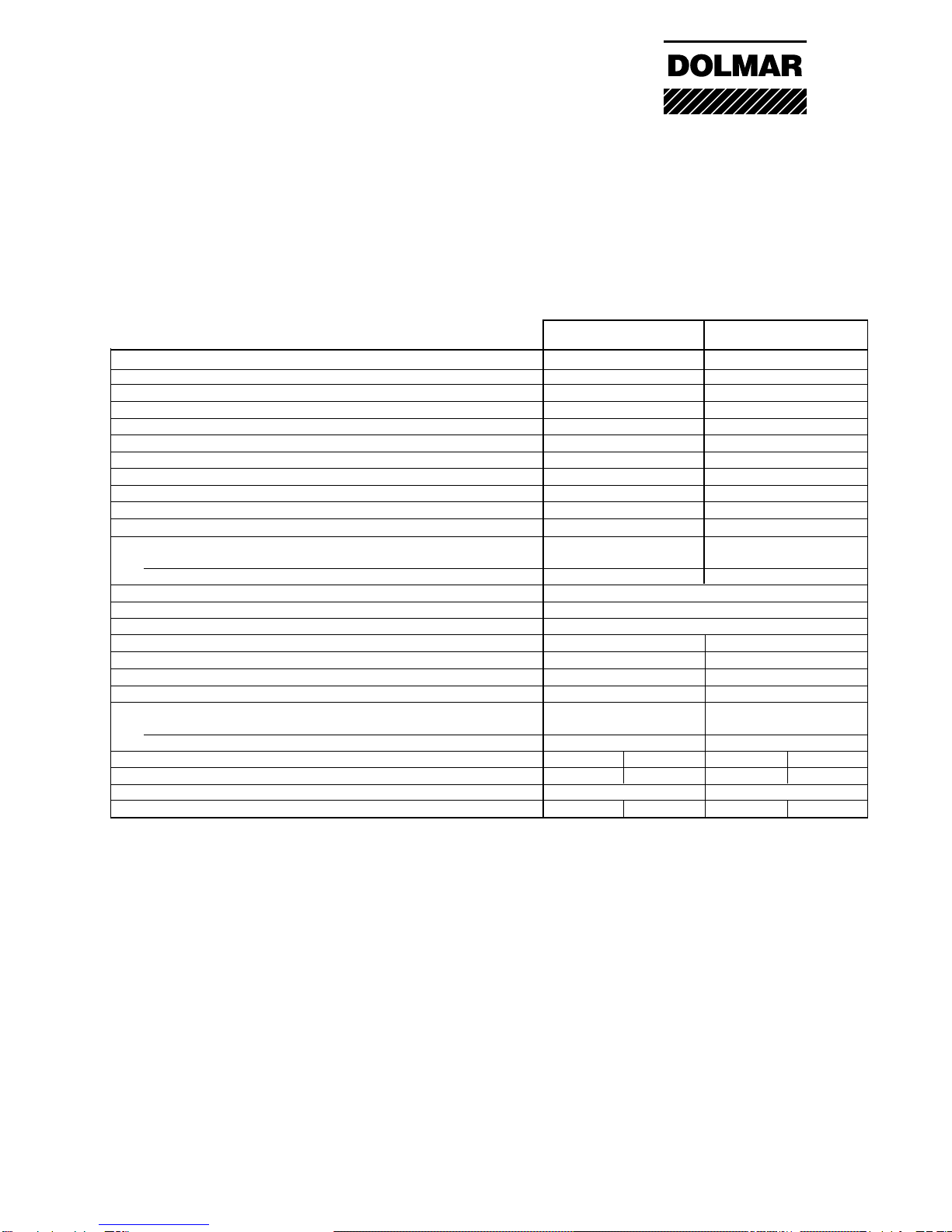
Dolmar PC-6212 HappyStart User manual

1
DOLMAR GmbH
PC-6212 HappyStart
PC-6214 HappyStart
PC-7312 HappyStart
PC-7314 HappyStart
Service Manual

2
DOLMAR GmbH
Index Special tools page 3
Technical data 4
02 Clutch, clutch drumm 5
04 Ignition 6 - 10
05 Starting system 11
06 Carburetor, intake system 12-13
07 Cover, air filter 14
08 Front handle, rubber mounts 15
09 Fuel filter 16
10 Cylinder, piston 17
11 Crankcase, crankshaft 18
12 Checking operation 19
13 Cutting attachment 20 - 21
Torques 22
Notizen 23
Index

3
DOLMAR GmbH
Special tools
Puller for Flywheel
957.427.010 Puller for ball bearing
Counter support (1) 955.102.015
Inside pulller (2) 955.102.025
Mounting tool for
clutch hub
944.500.570
2
Set of pistonring tension belt (1)
944.600.001
Piston stop wedge (2)
944.602.000
1
1
2
1
2
Puller for oil seals
944.500.900
Screw driver Torx (T27)
(1) 944.500.860
(2) 944.500.862

4
DOLMAR GmbH
Technical data
Displacement cm362 73
Bore mm 46 50
Stroke mm 37 37
Max. power kW 3,3 4,2
Max. torque Nm 4,0 5,0
Idling speed 1/min 2.500 2.500
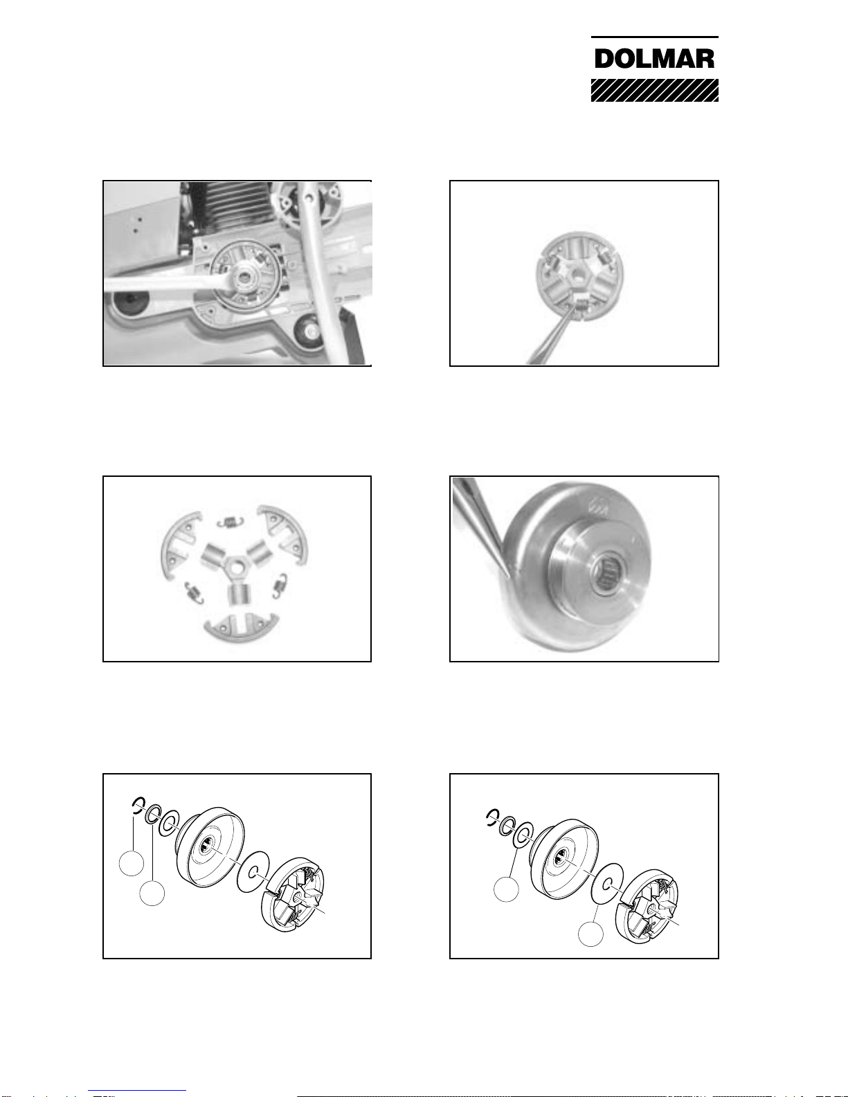
Clutch engagement speed 1/min 3.800 3.800
Engine speed limitation 1/min 9.350 9.350
Max. spindle speed 1/min 4.300 4.300
Sound pressure level LpA eq per EN 1454 1) 4) dB (A) 97 99
Sound power level LWA eq per EN 1454 1) dB (A) 109 110
Vibration acceleration ah,w per EN 1454
- Tubular handle (idle/rated spindle speed) m/s27 / 5 7 / 6
- Rear handle (idle/rated spindle speed) m/s28 / 6 8 / 7
Carburetor (diaphragm carburetor) Type TILLOTSON HS-273 A
Ignition system (with speed limitation) Type electronic
Spark plug Type
NGK BPMR 7A / BOSCH WSR 6F / CHAMPION RCJ 6Y
Electrode gap mm 0,5 0,5
Fuel consumption at max. load per ISO 8893 kg/h 1,65 2,1
Specific consumption at max. load per ISO 8893 g/kWh 500 500
Fuel tank capacity l 1,1 1,1
Mixture ratio (fuel/two-stroke oil)
- when using DOLMAR HP 100 high-performance oil 100:1 100:1
- when using DOLMAR oil 50:1 50:1
Cutting disc for 80 m/sec. 2) (DSA approved): dimensions mm
300 / 20,0 / 5
3)
350 / 25,4 / 5
3)
300 / 20,0 / 5
3)
350 / 25,4 / 5
3)
Arbor diameter mm 20,0 25,4 20,0 25,4
V-belt AVX 838 LA AVX 838 LA
Overall weight (tanks empty, without cutting disc ) kg 9,7 9,9 9,8 10
1) Figures derived in equal part from idle and max.-speed operation.
2) Circumference speed at max. engine speed
3) Outside diameter / arbor hole / thickness
4) At the workplace (at user's ear)
PC-6212 PC-6214 PC-7312 PC-7314

5
DOLMAR GmbH
1
2
3
45
68
02 Clutch, clutch drum
9
11
12
13
7
02-01 Dismantling the clutch/drum
To remove the clutch and drum, the piston
must be blocked. To do this, unscrew the 3
screws (9) fixing the muffler and insert the
piston stop wedge (944.602.000) in to the
exhaust port of the cylinder (11).
02-01 Dismantling the clutch/drum
The side strut is fixed with 3 screws (6) to
the tank and the collector (7) for the right
upper damper device.
02-01 Dismantling the clutch/drum
The cover for the V-belt is fixed to the crank-
case with 3 screws (8).
02-01 Mounting muffler and heat plate
When mounting the muffler ensure that the
heat plate is installed correctly (see drawing).
Note: The heat plate (12) comes directly on to
the cylinder, then the gasket (13) and muffler.
02-01 Dismantling the clutch/drum
To remove the cutting device, loosen the
fixing screws (4). Remove screw (5) to the
point where the end of the screw projects
from the cover (arrow).
02-01 Dismantling the clutch/drum
To dismantle the clutch and drum, remove the
cutting device (1), strut (2) and V-belt cover
(3).

6
DOLMAR GmbH
123
4
04 Ignition system
02-02 Mounting the clutch/drum
When mounting the drum and the clutch, be
carefultomountthewashersintherightorder.
(1) Ring (sits in the groove of the crankshaft)
(2) End collar (with recess towards ring)
02-02 Dismantling the clutch/drum
Unscrew the clutch with the special tool (parts
no. 944.500.570) and a 19mm wrench.
Caution: left-handed thread
02-02 Mounting the clutch/drum
(3) Guide washer
(4) Clutch guide washer,before assembly,
press into the support on the back of the
clutch hub.
02-01 Repairing the clutch
The tension springs of the clutch can be
removed/ replaced with pointed pliers. If
spares are required, the 3 tension springs
are only available as individual parts.
02-02 Mounting the drum
Before installing the clutch drum, the needle
bearing that is pressed in must be greased.
(Multipurpose grease 944.360.000)
02-01 Repairing the clutch
The tension springs should only be replaced
as a set if replacement is required.
If the hub / fly weight is defective, the com-
plete clutch must be replaced.

7
DOLMAR GmbH
STOP
9
10
11
1
0,5 mm
214
32
04 Ignition system
04-01 Checking the spark plug
Remove filter hood.
Pull spark plug socket (1) off the spark plug
and remove spark plug (2).
04-01 Checking the spark plug
Connect spark plug (2) with plug socket and
hold to earth (3). Pull out starter cable. If no
spark is produced, repeat procedure with new
spark plug.
Note: Switch (4) must be in position “I”.
04-01 Checking the spark plug
The spark plug has serious oil carbon depos-
its. Clean or replace spark plug.
04-01 Checking the spark plug
Combustion and motor performance will be
improved if the spark plugs function properly.
Dirty or faulty spark plugs should therefore
be cleaned or replaced.
04-02 Replacing the plug connector
Hold the plug connector spring using pointed
pliers and push the rubber cap backwards
over the ignition cable.
Note: grease the ignition cable slightly
beforehand.
04-01 Checking the spark plug
Spark plug is showing signs of wear (burning
off) on the middle electrode.
Spark plug must be replaced.

8
DOLMAR GmbH
34
1
2a
2
04 Ignition system
04-03 Removing the ignition/ short circuit
cable
Unscrew the starter device that is fixed with 4
screws.
04-03 Removing the ignition/ short circuit
cable
Unscrew filter hood (07-03).
Remove ignition and short circuit cable from
the guide (1) of the hood.
04-03 Removing the ignition/ short circuit
cable
Unscrew ignition from the ignition armature.
Loosen short circuit cable from the socket
connection (arrow).
04-03 Removing the ignition/ short circuit
cable
Remove hood - to do this, unscrew the 3
screws (2).
The screw (2a) is also the fixing for the earth
cable.
04-03 Removing the ignition/ short circuit
cable
Loosen the locking device of the intake elbow
from the tank housing. To do this, push both
levers inwards (arrow) and lift the intake
elbow slightly.
04-03 Removing the ignition/ short circuit
cable
Loosen the hose clamp (3) of the intake hose.
Pull the suction hose (4) off the cylinder.

9
DOLMAR GmbH
Neues Foto
4
3
4
2
1
04 Ignition system
04-03 Removing the ignition/ short circuit
cable
Push throttle control rod towards the cylinder
using pointed pliers, pulling upwards out of
the guide of the gas grip (arrow).
04-03 Removing the ignition/ short circuit
cable
Remove intake elbow with carburetor and
choke shaft from the tank housing.
04-03 Assembling the ignition/ short
circuit cable
When mounting the short circuit cable, make
sure that the connection between the connec-
tor lug of the short circuit cable and the
contact spring is in order (arrow).
04-03 Removing the ignition/ short circuit
cable
Pull short circuit cable (1) from its place in the
choke shaft (2).
Loosen earth cable (3) from the socket con-
nection of the contact spring (4).
04-03 Assembling the ignition/ short circuit
cable
As a safety measure, the short circuit cable
will be laid during assembly in the brackets
underneath the ignition cable.
04-03 Assembling the ignition/ short circuit
cable
Twist ignition cable into the ignition armature.
Note: To prevent moisture leaking in, fill
protective cap (4) with silicon paste
980.007.100 before replacing.

10
DOLMAR GmbH
1
3
2
4
04 Ignition system
04-04 Removing the ignition armature
Unscrew starting device.
Remove the two screws (1) of the ignition
armature. Clip off ignition and short circuit
cable.
04-04 Mounting the ignition armature
Connect ignition and short circuit cable.
Position setting gauge 944.500.890 (arrow)
between ignition device and magnet on the
flywheel. Press ignition device firmly whilst at
the same time tightening the screws evenly.
04-05 Mounting the flywheel
Before mounting the flywheel, the cone seat
and the crankshaft (4) must be cleaned.
Note. The flywheel is tightened with a torque
of 30Nm (see page 22).
04-04 Checking the ignition armature
In the event of a fault, first check the ignition
earth connection. To do this, loosen and then
tighten the screws (1) a few times. then check
ignition once again.
04-05 Removing the flywheel
Block the transmission using the piston stop
wedge. Unscrew bolt (2) and remove washer
(3). Remove flywheel with pulling device
957.427.010.
Warning: to avoid damage to the crankshaft
always use the protective cap including with
the pulling device.

11
DOLMAR GmbH
13
4
2
3
45
22
18
21
19 20
17
6
89
5
1
2
7
05-02 Pretensioning the return spring
Wrap the starter cable as far as possible
around the drum. Hold cable tight and turn the
drum with the cable 2-3 times to pretension.
05-02 Checking the return spring
When the starter cable is fully extended, the
rope drum must still turn at least half a turn.
05-02 Removing the return spring
To remove the return spring, remove the
circlip ring (3), the return spring (4) is in a
cartridge which is fixed to the fan housing with
three screws (5).
Note: Grease new spring (944.360.000)
05-02 Mounting the return spring /starter
cable
Thread cable through, knotting (6) into the
cable drum and knotting (7) into the starter
grip (8). The washer (9) is mounted between
the starter grip and the knot.
Note: solder cable ends
05-02 Removing the starter
Remove air duct (1).
Relieve the tension on the return spring by
pulling out the starter cable (2) slightly. Hold
cable drum and remove cable from rope
drum.Let drum spool back slowly.
05 Startering system
05-03 Replacing the set of bolt/ratchet
Knock out the bolts with a punch (arrow). To
assemble, push the bolt in so far that there is
only a crack of 0.15-0.2 mm between the
ratchet and the bolt (5). For mounting the bolt,
use glue 980.009.000.

12
DOLMAR GmbH
S
H
L
98
7
8
5
6
3
1
4
2
06-01 Setting the carburetor "L"
For the basic setting, turn in the idling nozzle
“L”carefully as far as it will go. Then back off
“L”nozzle = 11/8.
For fine tuning, the “L”nozzle only needs to
be changed by max. +/- 1/8 of a turn.
06-01 Setting the carburetor "S"
When during idling the engine speed is too
high (moving of cutting disc) or too low (en-
gine stalls), correct the the setting of idling
screw "S" (speed) accordingly.
06-08 Intake hose
Pull the intake hose (7) out of the intake
elbow and check for damage. Replace the
insert (8) in the intake hose again before
assembling the carburetor.
06-05 Removing the carburetor
Remove the carburetor from the intake
elbow.
The seal (5) must not block the bore (6) for
ventilating the control side of the carburetor
(compensation system).
06-04 Removing the carburetor
Remove intake elbow with carburetor.
Remove choke shaft (1), choke rod (2) and
throttle control rod (3). Unscrew the two fixing
screws (4).
06-01 Setting the carburetor
The main nozzle “H”is set at the factory to
11/8 revolutions.
To reset, the carburetor must be removed.
06 Carburetor

13
DOLMAR GmbH
12
37
9
8
10
6
4
5
10
06 Carburetor
06-03 Carburetor - testing the control
membrane
After removing the control diaphragm, it
must remain flat. The rim around the stiffen-
ing plate (7) must be even. Faulty diaphragm
must be replaced immediately.
06-04 Carburetor - dismantling the pump
side
Unscrew cover (8). Remove seal (9) and
diaphragm (10) from the carburetor.
06-03 Carburetor - testing the control unit
After removing the control diaphragm,
remove the intake pin with valve rocker and
spring.
Note: If there is visible wear (arrows), the
control unit must be replaced.
06-03 Carburetor - dismantling the con-
trol side
Unscrew cover (1). Carefully remove the
seal (2) and diaphragm (3) from the control
lever (4). Remove control lever, spring (5)
and inlet needle (6) from the carburetor.
06-04 Carburetor - Testing the pump mem-
brane
The two valve flaps (arrow) must rest flat on the
body of the carburetor. Damaged diaphragms
must be replaced immediately, as starting and
running problems may otherwise occur.
06-04 Carburetor - Testing the fuel sieve
The fuel filter (11) may be carefully removed
from the carburetor body for cleaning with a
pointed object. After cleaning replace the fuel
filter with a pin.

14
DOLMAR GmbH
1
3
24
5
6
5
07 Hood system / Air filter / Winter operation
07-05 Filter system
Only well-maintained filters will guarantee
efficient engine performance and a long
working life. Damaged or worn filters must
therefore be replaced.
07-06 Winter heating
Temperatures below zero may cause the filter/
carburetor to freeze.
Remove summer-winter insert from summer
mode(5)andinsertinwintermode(6)asshown.
Return when temperature is above 0°C.
07-04 Clean filter - inside filter
The inside filter should also be washed out
in luke-warm soapy water.
07-04 Cleaning the filter - paper cartridge
Unscrew the 4 screws on the cover hood (4).
To clean, fan the paper cartridge out slightly
and tap gently.
Note: never wash the paper cartridge to clean
it.
07-04 Cleaning the filter - pre-filter
Clean the pre-filter in luke-warm soapy water
using normal washing-up liquid. Dry before
replacing.
Note: under extrem dusty conditions, the
pre-filter may need to be oiled slightly.
07-03 Removing the air filter
Remover filter hood (5), unscrew cover hood
(4).
Filter system consists of the pre-filter (1), the
paper cartridge (2) and the inside filter (3).

15
DOLMAR GmbH
4
3
1
2
08-01 Removing and replacing the
bracket handle
To dismantle the front handle, the strut (1)
with 3 screws and the foot (2) with 2 screws
must be unscrewed.
08-03 Replacing the vibration absorber
The system consists of 4 vibration absorb-
ers, 3 of which are on the clutch side.
To dismantle them, the front handle, filter
system and tank must be removed.
08-03 Replacing the vibration absorbers
The fourth vibration absorber is on the
magnet side.
To dismantle it, the starter device must be
removed.
08-03 Replacing the vibration absorbers
The vibration absorbers are slotted into the
housing. Mount the sleeves (3+4) with the
collars inwards.
Grease vibration absorbers (980.007.100).
08 Front handle with stand / vibration damping system

16
DOLMAR GmbH
B
C
2-3mm
(.080”-0.12”)
;;
;;
2
2
3
1
54
6
8
7
09-02 Removing the ventilation valve
Push the ventilation valve with a pin into the
tank (arrow) and remove with pointed pliers
through the filler opening.
09 Fuel tank
09-02 Inserting the ventilation valve
Press the new ventilation valve with a pin
into the housing until the white sinter plastic
project about 2-3 mm beyond the tank.
09-03 Replacing the throttle lever mecha-
nism
Push the two cylindrical pins (1) out of the
handle dish (2). The throttle lever (3), spring
(4) and throttle lock (5). The throttle lock (6)
for half throttle can also now be replaced.
09-04 Replacing the fuel pipe
Unscrew tank cap, remove suction head (7)
from tank and pull off the suction pipe (8). Pull
suction pipe upwards out of the tank.
09-05 Testing the fuel filter
Dirty felt filters or filters which have become
hardened/blocked with fuel will lead to leaning
of the fuel/air mix and will damage the engine.
Note: They fuel filter must therefore be
cheked/ replaced regularly.
09-05 Testing the fuel filter
A fingernail test can be used to check
whether the filter is blocked.
Easy to push in = filter OK
Cannot be pushed in = filter blocked, replace
as a matter of urgency.

17
DOLMAR GmbH
1
1
4
5
3
2
10 Cylinder / piston / decompression valve
10-01 Dismantling the cylinder
To dismantle the cylinder, unscrew the 4
screws (1) from the cylinder foot.
Pull cylinder off crankcase and piston.
10-01 Dismantling the cylinder - piston
Remove piston pin securing ring (2) from the
annular slot in the piston using pointed pliers.
Push piston pin out.
Note: During assembly, make sure the secur-
ing ring clicks completely into the groove.
10-01 Mounting the cylinder - piston
When mounting piston, the arrow on top of
the piston has to point in direction of muffler.
Note: Before assembling the piston ensure
that the cylinder base gasket (3) is fitted
correctly.
13-02 Testing the decompression valve
Unscrew valve and check valve seating (5)
and the hole in the cylinder for dirt. Replace
valve if dirty. Clean hole carefully.
10-01 Mounting the cylinder
After positioning the cylinder, tighten fixing
screw with a force of 14 Nm (see page 22).
10-01 Mounting the cylinder
Position the fork (4) of the piston ring tightening
device (parts no. 944.601.001) onto the crank-
case. Press the piston ring together using the
ring clamp. When positioning the cylinder, push
the ring clamp away downwards.

18
DOLMAR GmbH
12
3
4
11 Crankcase / Crankshaft
11-03 Replacing the crankshaft / bearing
First push bearing on to the crankshaft, then
insert crankshaft with bearing (5) into the
case, "KS". Place gasket on centering pins.
Note: To dismantle or assembly the bearings,
always heat the crankcase to 100-120°C.
11-03 Dismantling the crankcase
After removing the 5 fixing screws, separate
the crankcase carefully by tapping with a
plastic hammer.
11-03 Mounting the crankcase
Tighten the 5 fixing screws with a torque of
10 Nm (see page 22).
11-03 Complete crankcase
The complete crankcase is divided into the
crankcase magnet side (2) "MS", and the
crankcase clutch side (1) "KS".
11-03 Removing the crankcase "MS"
To dismantle the magnet side (MS), unscrew
the 4 fixing screws (3) and the left lower
screw (4).
11-03 Mounting the bearing / crankcase
Heat the crankcase "MS" and fitt bearing into
the case.
Note: The bearings faces with its open side
to the crankshaft. Before installation moisten
the bearings with "Loctite 601".
5

19
DOLMAR GmbH
12-03 Testing the carburetor
Test carburetor at 0.5 bar. 12-04 Tightening the screw connections
with a torque wrench
Fix the cylinder, crankcase and muffler
screws, plus flywheel nut and clutch hub with
the specified torque (see page 22).
12-02 Testing the ignition system
To test the ignition system / spark plug, use
test device no. 965 010 030.
12-03 Testing the carburetor
To test the carburetor in the installed state,
pull fuel line out off the fuel tank. Pull off the
fuel filter and attach pressure test device no.
965 004 000 to fuel line by using a connecting
nipple.
12 Testing

20
DOLMAR GmbH
P
T
F
E
P
T
F
E
1
5
3
6
4
8
9
7
11 12
13
17 16
10
2
13 Cutting attachment
13-02 Mounting the V-belt pulley
When mounting the pulley, make sure that the
shim 900.006.179 (6) is mounted between the
V-belt pulley and the ball bearing.
Note: The V-belt pulley is only fixed when the
cutting disk is mounted.
13-03 Replacing the drive axle
To remove the axle (7), the pressure disk (8)
and the V-belt pulley must be dismantled.
Note: when mounting the inner flange disk,
make sure that the spacer sleeve (9)
394.228.020 is mounted.
13-01 Replacing the pressure disc
Undo screw (1) and remove pressure disc.
Note: With the 25.4 mm (1") axle, the inner
flange is located behind the recess of the axle
(2). Remove axle and flange together.
13-02 Replacing the V-belt pulley
Block the V-belt pulley (3). To do this, push a
pin through the hole (4) in the V-belt pulley
into the housing. Remove screw (5).
13-05 Cutter guard holding attachments
When mounting, make sure that:
inside: outside:
- pressure ring (11) - housing (15)
- Teflon ring (12) - Teflon ring (12) -
- rubber part (13) - locking plate (16)
- rubber part (17)
15
13-04 Removing the complete pressure ring
Unscrew the 3 screws with springs (10), the
housing (15) and the pressure ring (11).
Note: the screws (10) have to be fitted in an
angle of 1200and are tightened with 10 Nm.
This manual suits for next models
3
Table of contents
Other Dolmar Saw manuals

Dolmar
Dolmar AS-1212LG User manual

Dolmar
Dolmar PC-6530 Instruction and safety Instruction Manual

Dolmar
Dolmar PS-6100 Instruction Manual

Dolmar
Dolmar PS-32 User guide

Dolmar
Dolmar PS-32 User guide

Dolmar
Dolmar PS-3410 User manual

Dolmar
Dolmar AS-1812 User manual

Dolmar
Dolmar ES-33A User manual

Dolmar
Dolmar PS-32 User guide

Dolmar
Dolmar PS-32 User guide