manuals.online logo
Brands
  1. Home
  2. •
  3. Brands
  4. •
  5. Dometic
  6. •
  7. Control System
  8. •
  9. Dometic Go Power! GP-BMG User manual

Dometic Go Power! GP-BMG User manual

COMPONENTS
Size
Resolution
Touchscreen
Viewing Angle
Supply Voltage
Dimensions
Operating Temperature Range
Storage Temperature Range
Connectivity Range
WiFi Bandwidth
Humidity
Max Supply Current @ 12 VDC Input
Max Supply Current @ 24 VDC Input
3.2”
320x240
Resistive
Short axis 70° | Long axis 55°
7.5 to 76 VDC
4.77” x 2.84” x 0.51”
-20 to +50 °C
-30 to +70 °C
50 meters (unobstructed)
2.4 Ghz
5-95 % RH, non-condensing
150 mA
80 mA
GP-BMG
BATTERY MANAGER
Quick Start Guide
SPECIFICATIONS
Find tech tips, manuals and support at gopowersolar.com/BMG
8
7
6
5
4
3
1
2
9
10
Scan for full manual
No. Descrip�on No. Descrip�on
1 6 Input/Output Current (+/-)
Ah Remaining
2Battery Percentage
Remaining 7
Settings
3 Battery Temperature 8
Battery Image Indicator
9
10
Time Remaining
Connectivity Icon
4 Battery Voltage
5Input/Output Power (+/-)
NO. DESCRIPTION NO. DESCRIPTION
GP-Display
GP Shunt NOTE: This kit can be purchased as separate items
2x RV-C Adapter Cable
1x RV-C Extension Cable, 25ft
1x GP-Shunt
Power Cable
DISPLAY
ELECTRICAL
MECHANICAL
ENVIRONMENTAL
COMMUNICATIONS
INSTALLATION AND WIRING - OVERVIEW
The GP-BMG shunt should be mounted as close to the battery as possible and the
remote display is intended to be mounted on a wall.
RECOMMENDED TOOLS
•Wrench
•Drill
•2" hole saw
•2 ring terminals of appropriate size for battery cable
•Crimp tool for ring terminals
WIRING DIAGRAMS
The following wiring diagrams will be referenced in the next section.
SETUP
INSTALLATION
1. Before doing anything, disconnect all wires from the negative side of the battery.
1. Tap the SETTINGS icon on the
touchscreen display.
2.
•Connection between Shunt and display includes connecting the RV-C Adapter
Cable to the RV-C Extension Cable to the second RV-C Adapter Cable. (Cable
is not shielded)
2. Next, set the battery type and system voltage.
3. Followed by setting the system size.
4. Lastly, enable an external relay if you have one,
and you are done.
3. Install the shunt as shown in the wiring diagram on the previous page.
Note: The negative terminal of the battery must connect directly to the proper
side of the shunt and there should be no other connections to the negative
terminal of the battery for accurate measurements.
4. Connect the shunt to the remote display using the included shielded cable.
Loads &
Sources
Battery
Bank
Relay
GP-Shunt
GP-Display
+_
NOTE: The screen will enter "sleep" mode after 5 seconds of inactivity. If the screen is black, simply
press anywhere on the screen and wait for it to awaken. The auto dim feature can be disabled in
the Screen - Brightness settings.
Connect the GP-Shunt Power Cable to Battery Positive connection.
•Left side of Shunt
connected to Battery,
Right side to loads
Battery Load

Other Dometic Control System manuals

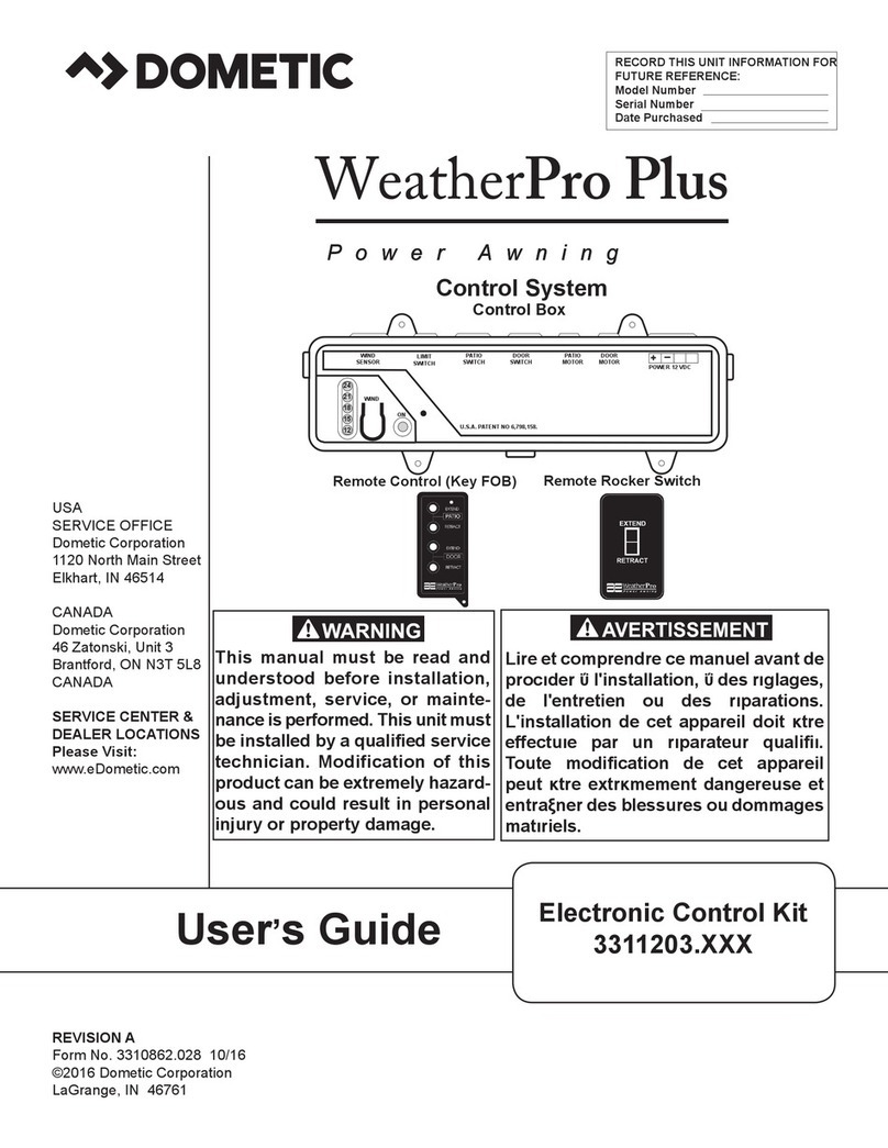
Dometic WeatherPro Plus User manual

Dometic

Dometic WeatherPro Plus User manual

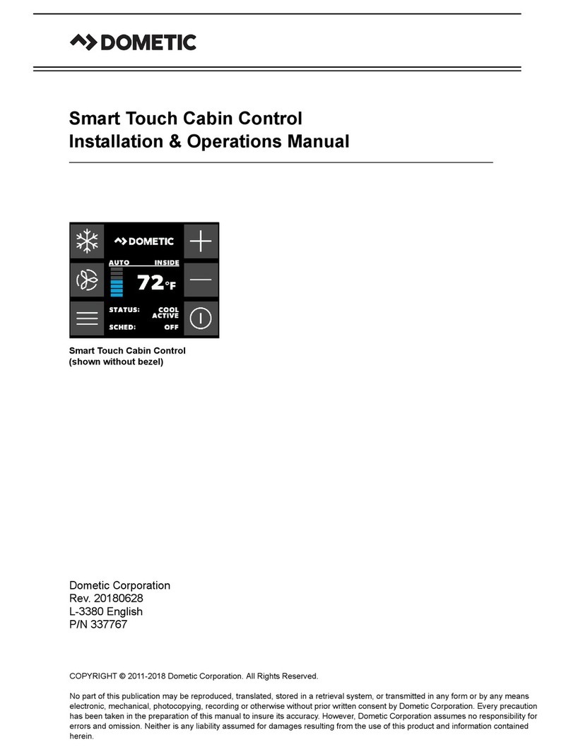
Dometic Smart Touch Cabin Control User manual

Dometic

Dometic Smart Touch Cabin Control User manual

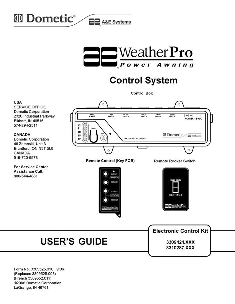
Dometic WeatherPro User manual

Dometic

Dometic WeatherPro User manual

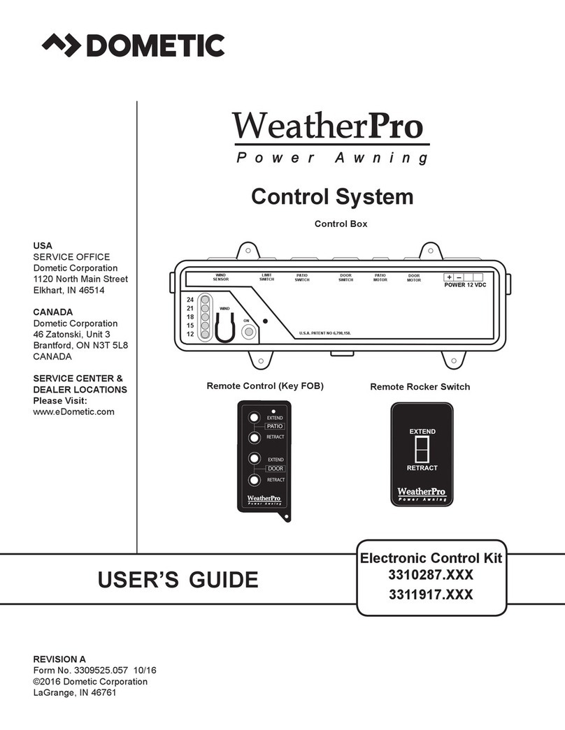
Dometic Weather  Pro 3310287 Series User manual

Dometic

Dometic Weather Pro 3310287 Series User manual

Dometic WeatherPro User manual

Dometic

Dometic WeatherPro User manual

Popular Control System manuals by other brands

Comelit simplehome Technical manual

Comelit

Comelit simplehome Technical manual

Ez-Boom 2010 Quick reference card

Ez-Boom

Ez-Boom 2010 Quick reference card

GUARDIAN GEAR ZW8198 Assembly instructions

GUARDIAN GEAR

GUARDIAN GEAR ZW8198 Assembly instructions

Fly Sky FS-iA6B Operation Notes

Fly Sky

Fly Sky FS-iA6B Operation Notes

ARC 6001Z instructions

ARC

ARC 6001Z instructions

Kolbinger ADAM-5000 Series user manual

Kolbinger

Kolbinger ADAM-5000 Series user manual

Endress+Hauser Cerabar PMC21 operating instructions

Endress+Hauser

Endress+Hauser Cerabar PMC21 operating instructions

ASCO POWER TECHNOLOGIES 5010 Operator's manual

ASCO POWER TECHNOLOGIES

ASCO POWER TECHNOLOGIES 5010 Operator's manual

Lutron Electronics RadioRA-SR Setup guide

Lutron Electronics

Lutron Electronics RadioRA-SR Setup guide

Gilderfluke & Co Sd-50/0 manual

Gilderfluke & Co

Gilderfluke & Co Sd-50/0 manual

IN-COMMAND NCSP35 troubleshooting guide

IN-COMMAND

IN-COMMAND NCSP35 troubleshooting guide

Siemens ACC AP Technical manual

Siemens

Siemens ACC AP Technical manual

Klimor EVO -T Operation and maintenance manual

Klimor

Klimor EVO -T Operation and maintenance manual

Neets OsCar installation manual

Neets

Neets OsCar installation manual

elsner elektronik WS1000 Style Installation and operation

elsner elektronik

elsner elektronik WS1000 Style Installation and operation

BST eltromat EKR 1500 Translation of the original operating manual

BST

BST eltromat EKR 1500 Translation of the original operating manual

Velux KFX 100 instructions

Velux

Velux KFX 100 instructions

Sartorius DCU 3 Operator's handbook

Sartorius

Sartorius DCU 3 Operator's handbook

manuals.online logo
manuals.online logoBrands
  • About & Mission
  • Contact us
  • Privacy Policy
  • Terms and Conditions

Copyright 2025 Manuals.Online. All Rights Reserved.