Dometic Type I User manual

2004-05-12 Vers. 1.0 / 2011
MBA 02/2011
N 8
Bedienungsanleitung
Dometic Schaltnetzteile 230V/12V für Freizeitfahrzeuge
Dometic converters 230V/12V for recreational vehicles
Dometic convertisseurs 230V/12V pour véhicules de loisirs
Dometic convertitori 230V / 12V per veicoli ricreazionali
Dometic omvormer 230V / 12V voor recreatievoertuigen
& Installationsanleitung
EN
DE
IT
NL
FR
Type I Type II
Schaltnetzteile für Freizeitfahrzeuge

©Dometic Light Systems GmbH - 2011 - Änderungen vorbehalten
2
Dometic Light Systems GmbH
Dillenburger Straße 59
D-35685 Dillenburg
www.dometic.com
Deutsch . . . . . . . . . . . . . . . . . . . . . . . . . . . . . . . . . . . . . . . . . . . . . . . . . . . 3
English . . . . . . . . . . . . . . . . . . . . . . . . . . . . . . . . . . . . . . . . . . . . . . . . . . . . 9
Français . . . . . . . . . . . . . . . . . . . . . . . . . . . . . . . . . . . . . . . . . . . . . . . . . . 15
Italiano . . . . . . . . . . . . . . . . . . . . . . . . . . . . . . . . . . . . . . . . . . . . . . . . . . . 21
Nederlands . . . . . . . . . . . . . . . . . . . . . . . . . . . . . . . . . . . . . . . . . . . . . . . . 27

3
1.0 Allgemeines . . . . . . . . . . . . . . . . . . . . . . . . . . . . . . . . . . . . . . . . . . . 4
1.1 Produktbeschreibung und Verwendung . . . . . . . . . . . . . . . . . . . . . . . . . . . . . . . . . . . . . . . . . . . 4
1.2 Hinweise zu dieser Bedienungsanleitung . . . . . . . . . . . . . . . . . . . . . . . . . . . . . . . . . . . . . . . . . 4
1.3 Urheberschutz . . . . . . . . . . . . . . . . . . . . . . . . . . . . . . . . . . . . . . . . . . . . . . . . . . . . . . . . . . . . . . 4
1.4 Erklärung der verwendeten Symbole . . . . . . . . . . . . . . . . . . . . . . . . . . . . . . . . . . . . . . . . . . . . . 4
1.5 Gewährleistung . . . . . . . . . . . . . . . . . . . . . . . . . . . . . . . . . . . . . . . . . . . . . . . . . . . . . . . . . . . . . 5
1.6 Haftungsbeschränkung . . . . . . . . . . . . . . . . . . . . . . . . . . . . . . . . . . . . . . . . . . . . . . . . . . . . . . . 5
2.0 Sicherheitshinweise . . . . . . . . . . . . . . . . . . . . . . . . . . . . . . . . . . . . . 5
2.1 Bestimmungsgemäße Verwendung . . . . . . . . . . . . . . . . . . . . . . . . . . . . . . . . . . . . . . . . . . . . . . 5
2.2 Verantwortung des Nutzers . . . . . . . . . . . . . . . . . . . . . . . . . . . . . . . . . . . . . . . . . . . . . . . . . . . . 5
3.0 Bedienung des AC/DC-Wandlers . . . . . . . . . . . . . . . . . . . . . . . . . . 6
3.1 Einschalten . . . . . . . . . . . . . . . . . . . . . . . . . . . . . . . . . . . . . . . . . . . . . . . . . . . . . . . . . . . . . . . . . 6
3.2 Schutzeinrichtungen . . . . . . . . . . . . . . . . . . . . . . . . . . . . . . . . . . . . . . . . . . . . . . . . . . . . . . . . . . 6
3.2.1 Übertemperaturschutz . . . . . . . . . . . . . . . . . . . . . . . . . . . . . . . . . . . . . . . . . . . . . . . . . . . . . . . . . . . . . . . . 6
3.2.2 Überlastschutz und Kurzschluss . . . . . . . . . . . . . . . . . . . . . . . . . . . . . . . . . . . . . . . . . . . . . . . . . . . . . . . . 6
3.2.3 Überspannungsschutz . . . . . . . . . . . . . . . . . . . . . . . . . . . . . . . . . . . . . . . . . . . . . . . . . . . . . . . . . . . . . . . . 7
3.2.4 Sicherungen . . . . . . . . . . . . . . . . . . . . . . . . . . . . . . . . . . . . . . . . . . . . . . . . . . . . . . . . . . . . . . . . . . . . . . . . 7
3.3 Maßnahmen bei Störungen . . . . . . . . . . . . . . . . . . . . . . . . . . . . . . . . . . . . . . . . . . . . . . . . . . . . 7
4.0 Installation . . . . . . . . . . . . . . . . . . . . . . . . . . . . . . . . . . . . . . . . . . . . 8
4.1 Einbau . . . . . . . . . . . . . . . . . . . . . . . . . . . . . . . . . . . . . . . . . . . . . . . . . . . . . . . . . . . . . . . . . . . . 8
4.1.1 Vertikaler Einbau . . . . . . . . . . . . . . . . . . . . . . . . . . . . . . . . . . . . . . . . . . . . . . . . . . . . . . . . . . . . . . . . . . . . . 8
4.1.2 Horizontaler Einbau . . . . . . . . . . . . . . . . . . . . . . . . . . . . . . . . . . . . . . . . . . . . . . . . . . . . . . . . . . . . . . . . . . 8
5.0 Technische Daten . . . . . . . . . . . . . . . . . . . . . . . . . . . . . . . . . . . . . . 33
5.1 Type I . . . . . . . . . . . . . . . . . . . . . . . . . . . . . . . . . . . . . . . . . . . . . . . . . . . . . . . . . . . . . . . . . . . . . 33
5.2 Type IIa . . . . . . . . . . . . . . . . . . . . . . . . . . . . . . . . . . . . . . . . . . . . . . . . . . . . . . . . . . . . . . . . . . . . 34
5.3 Type IIb . . . . . . . . . . . . . . . . . . . . . . . . . . . . . . . . . . . . . . . . . . . . . . . . . . . . . . . . . . . . . . . . . . . . 35
6.0 Tabelle . . . . . . . . . . . . . . . . . . . . . . . . . . . . . . . . . . . . . . . . . . . . . . . 36
Inhaltsverzeichnis
Deutsch

4
1.0 Allgemeines
Dometic AC/DC-Wandler werden zur
Versorgung von 12V-Geräten im Permanent-
betrieb eingesetzt. Die Eingangsspannung
kommt dabei entweder von der 230V-
Wechselstromnetzversorgung oder einer 12V-
Gleichstromquelle, wobei die 230V-
Wechselspannung Vorrang hat.
1.1 Produktbeschreibung und
Verwendung
Die Angaben, Texte und Abbildungen in dieser
Anleitung sind urheberrechtlich geschützt und
unterliegen den gewerblichen Schutzrechten.
Kein Teil dieser Anleitung darf ohne die schrift-
liche Genehmigung der Dometic Light
Systems GmbH, , reproduziert, kopiert oder
sonstwie verwendet werden.
1.3 Urheberschutz
Bevor Sie den AC/DC-Wandler nutzen,
lesen Sie die Bedienungsanleitung bitte
sorgfältig durch.
Diese Anleitung gibt Ihnen die nötigen
Hinweise für den richtigen Gebrauch des
AC/DC-Wandlers. Beachten Sie besonders
die Sicherheitshinweise. Die Einhaltung der
Hinweise und Handlungsanweisungen ist
wichtig für den sicheren Umgang mit Ihrem
AC/DC-Wandler und schützt Sie und den
AC/DC-Wandler vor Schäden. Das Gelesene
muss verstanden worden sein, bevor Sie eine
Maßnahme durchführen.
Bewahren Sie diese Bedienungsanleitung
sorgfältig in der Nähe des Gerätes auf,
sodass sie jederzeit verwendet werden
kann.
1.2 Hinweise zu dieser
Bedienungsanleitung
1.4 Erklärung der verwendeten
Symbole
Allgemeines
Warnhinweise sind durch Symbole gekenn-
zeichnet. Ein ergänzender Text erläutert Ihnen
den Grad der Gefährdung.
Beachten Sie diese Warnhinweise sehr
genau. Damit schützen Sie sich, andere
Personen und das Gerät vor Schäden.
Warnhinweise
Information
WARNUNG kennzeichnet eine mögliche
Gefahrensituation, die zum Tod oder einer ern-
sten Verletzung führen kann, wenn die angege-
benen Anweisungen nicht befolgt werden.
WARNUNG!
VORSICHT kennzeichnet eine mögliche
Gefahrensituation, die zu leichten oder mittle-
ren Verletzungen führen kann, wenn die ange-
gebenen Anweisungen nicht befolgt werden.
VORSICHT!
INFORMATION gibt Ihnen ergänzende und
nützliche Hinweise zum Umgang mit dem
Gerät.
VORSICHT ohne Sicherheitssymbol kennzeich-
net eine mögliche Gefahrensituation, die zu
Beschädigungen des Gerätes führen kann,
wenn die angegebenen Anweisungen nicht
befolgt werden.
VORSICHT!

5
Sicherheitshinweise
Gewährleistungsabwicklungen erfolgen nach
der europäischen Richtlinie 44/1999/EC und
den landesüblichen Bedingungen. Störungen,
die auf fehlerhafte Bedienung zurückzuführen
sind, unterliegen nicht der Gewährleistung.
1.5 Gewährleistung
Alle Angaben und Hinweise in dieser
Bedienungsanleitung wurden unter
Berücksichtigung geltender Normen und
Vorschriften sowie dem Stand der Technik
erstellt. Dometic behält sich vor, jederzeit
Änderungen am Produkt vorzunehmen, die im
Interesse der Verbesserung des Produktes
und der Sicherheit angebracht sind.
Dometic übernimmt keine Haftung für
Schäden bei :
Nichtbeachtung der Bedienungsanleitung
nicht bestimmungsgemäßer Verwendung
Verwendung von nicht originalen
Ersatzteilen
Veränderungen und Eingriffen am Gerät
Einwirkung von Umgebungseinflüssen, wie
- Temperaturänderungen
- Luftfeuchtigkeit
1.6 Haftungsbeschränkung
Dometic AC/DC-Wandler werden zur
Versorgung von 12V-Geräten im Permanent-
betrieb eingesetzt.
2.1 Bestimmungsgemäße
Verwendung
Personen, die den Dometic AC/DC-Wandler
bedienen, müssen mit dem sicheren Umgang
vertraut sein und die Hinweise dieser
Bedienungsanleitung kennen.
Eine Nichtbeachtung der folgenden Sicher-
heitshinweise kann zu ernsten Beschädigun-
gen des Dometic AC/DC-Wandlers und der
angrenzenden Bereiche führen.
2.2 Verantwortung des Nutzers
2.0 Sicherheitshinweise
Nehmen Sie keine Änderungen, zusätzli-
che Installationen oder Reparaturen am
Dometic AC/DC-Wandler oder an der vom
Fahrzeughersteller ausgeführten Installa-
tion vor.
WARNUNG!
Der Dometic AC/DC-Wandler darf nicht in
Bereichen eingesetzt werden, in denen
Gas- oder Staubexplosionsgefahr
besteht.
WARNUNG!
Der Dometic AC/DC-Wandler darf weder
abgedeckt noch Umgebungsbedingungen
ausgesetzt sein, die die Belüftung der
Einheit beeinträchtigen.
VORSICHT!

6
Bedienung
3.1 Einschalten
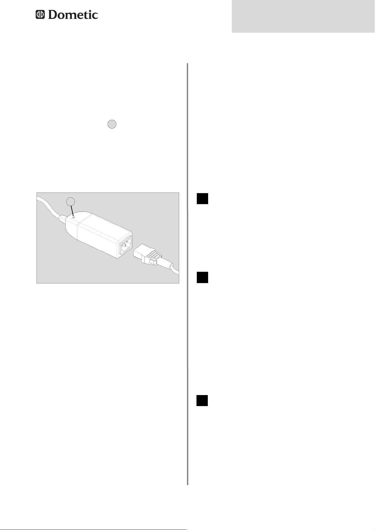
Geräte vom Typ 1 (siehe Abb. 4, S. 33) las-
sen sich über den ON/OFF Schalter ein-
und ausschalten. Bei grün aufleuchtender
LED unterhalb des ON/OFF-Schalters sind
230VAC-Eingangsspannung verfügbar.
Leuchtet die grüne LED nicht auf, liegt
keine 230V AC-Eingangsspannung an der
Einheit an, oder das Gerät hat durch Über-
hitzung abgeschaltet (siehe Pkt. 3.2.1).
Geräte vom Typ 2 a + b ( Abb. 5 und 6, S.
34 und 35) schalten sich ein, sobald 230V
Spannung am Anschluss zur Verfügung
steht.
Die Verbraucher können unabhängig vom
230V Betrieb über eine 12V DC-Energie-
quelle (z. B. Batterie) versorgt werden,
sofern diese mit dem Wandler verbunden
ist. Die interne Vorrangschaltung trennt
die 12VDC - Energiequelle automatisch,
sobald 230VAC anliegen. Der AC/DC
Wandler ist kein Ladegerät.
3.2 Schutzeinrichtungen
Bei einer Überhitzung der Einheit löst der
thermische Überlastschutz aus. Zum
Wiedereinschalten trennen Sie den Wandler
vom 230VAC- Netz Leitungsschutzschalter
auf OFF oder 230VAC Zuleitung zum
Fahrzeug abziehen ).
230VAC Versorgung
Sobald der Leitungsschutzschalter (im vor-
geschalteten Sicherungskasten ) in ON
Position ist und eine 230VAC Spannungs-
quelle am Fahrzeug angeschlossen wurde,
ist der AC/DC Wandler betriebsbereit.
12VDC Versorgung
Stehen die 230VAC nicht zur Verfügung,
aber am AC/DC Wandler ist eine 12VDC
Energiequelle ( z. B. Batterie ) angeschlos-
sen, so werden die Verbraucher hierüber
versorgt.
Sollte der thermische Überlastschutz wie-
derholt auslösen und das Gerät abschal-
ten, liegt die Ursache möglicherweise an
einer unzureichenden Belüftung. Ist dies
der Fall, sorgen Sie für eine bessere
Belüftung und starten Sie die Einheit
erneut.
Wenn danach der thermische Überlast-
schutz immer noch anspricht, nehmen Sie
bitte Kontakt zu einem autorisierten
Dometic Servicepartner auf.
3.2.1 Übertemperaturschutz
Zu Ihrer Sicherheit sind Dometic AC/DC-
Wandler mit verschiedenen Schutzfunktionen
ausgestattet.
3.0 Bedienung des
AC/DC-Wandlers
Der Überlastschutz spricht unter folgenden
Voraussetzungen an:
Bei mäßiger Überlast, die mit zunehmender
Betriebsdauer zu hohe Innentemperaturen
führt und in der Folge den oben genannten
thermischen Überlastschutz auslöst.
Dadurch sinkt die Ausgangsspannung, und
der Unterspannungsschutz löst aus.
Die Einheit ist mit einer internen Kurz-
schlussüberwachung ausgestattet.
Sobald ein voreingestellter Wert erreicht ist,
löst dieser Schutz aus und schaltet die
Einheit ab, ohne dass Sicherungen durch
brennen. In diesem Fall ist Vorsicht gebo-
ten.
3.2.2 Überlastschutz und Kurzschluss
Beachten Sie, dass über die Geräte aufgrund
der gerätespezifischen hohen Leistung hohe
Ströme fließen, obwohl sie nur eine 12V
Spannung erzeugen.
Achten Sie unbedingt darauf, dass die
Leistung der an dem jeweiligen Ausgang
angeschlossenen Verbraucher den Vorgaben
unter Punkt 3.2.4 entsprechen.
Änderungen an der Installation dürfen nur
durch autorisierte Fachkräfte in Abstimmung
mit dem Fahrzeughersteller durchgeführt wer-
den.

7
Bedienung
Abb. 1
Der Dometic Überspannungsschutz (OVP-
unit, Abb. 1) wird dem Schaltnetzteil vorge-
schaltet. Er trennt die Zuleitung, wenn die
Eingangsspannung ca. 270 V~ überschreitet.
Angeschlossene Geräte werden geschützt.
Eine rote Leuchtdiode (1) zeigt an, dass eine
Überspannung angelegen hat.
Der Dometic Überspannungsschutz setzt sich
selbst zurück, wenn die Spannung wieder
einen normalen Pegel erreicht hat. Die LED
leuchtet noch 20 bis 30 Minuten, nachdem die
Spannung wieder einen sicheren Pegel
erreicht hat.
3.2.3 Überspannungsschutz
Die Netzteile können mit unterschiedlichen
Sicherungen bestückt sein.
Bei der Installation ist unbedingt darauf zu
achten, dass die an den einzelnen
Sicherungen abgenommene Leistung max. 75
% des Nennwertes der jeweiligen Sicherung
betragen darf. Höhere Leistungen können auf-
grund des höheren Stromes zu Überhitzung
und zu einer Beschädigung führen.
Eine defekte Sicherung deutet in der Regel auf
einen Kurzschluss oder eine Überlast des 12
V-Ausgangs hin. Dies wird durch eine rot auf-
leuchtende LED neben der Sicherung signali-
siert (siehe Abb. 2) wenn ein Verbraucher
angeschlossen ist.
Eine fehlende Sicherung im Sicherungshalter
wird auch nur bei angeschlossenem
Verbraucher angezeigt. Versuchen Sie im Falle
einer defekten Sicherung die Ursache im 12 V
3.2.4 Sicherungen
Die 230 V und 12 V Ausgänge werden im
Netzbetrieb nicht versorgt, die grüne
LED leuchtet nicht.
a. Prüfen Sie, ob die Netzverbindung
getrennt wurde, ggf. diese wiederherstel-
len. Prüfen Sie, ob der Sicherungsautomat
abgeschaltet hat.
3.3 Maßnahmen bei Störungen
11
12 V Ausgänge werden im Netzbetrieb
nicht versorgt.
a. Prüfen Sie die 12 Volt Stecksicherungen,
defekte Sicherungen werden durch d i e
rote LED angezeigt. Ersetzen Sie ggf. die
Sicherungen gegen eine neue Sicherung
gleichen Typs und Stromstärke.
b. Prüfen Sie, ob das Gerät durch Überhit-
zung abgeschaltet hat, die grüne LED
leuchtet nicht. Schalten Sie das Gerät aus
und warten Sie ca. 2 Minuten, bevor Sie
das Gerät wieder einschalten.
2
12 V Ausgänge werden im Batterie-
betrieb nicht versorgt.
a. Prüfen Sie die 12 Volt Stecksicherungen,
defekte Sicherungen werden durch die rote
LED angezeigt. Ersetzen Sie ggf. die
Sicherungen gegen eine neue Sicherung
gleichen Typs und Stromstärke.
b. Prüfen Sie die Batterie und deren
Anschluss an dem Umformer.
3
Stromkreis zu lokalisieren und nach
Möglichkeit zu beheben. Schalten Sie vor
Austausch der Sicherung den AC/DC-
Wandler aus, oder trennen das Gerät von der
230VAC Versorgung. Ersetzen Sie eine defek-
te Sicherung ausschließlich durch eine neue
Sicherung des Typs ATO Type - LITTLEFUSE.
Schalten Sie die Einheit wieder ein (siehe Abb.
4). Sollte die Sicherung erneut auslösen, wen-
den Sie sich bitte an einen Servicepartner für
Dometic AC/DC-Wandler.
1

8
Installation
4.0 Installation
Installieren Sie den AC/DC-Wandler an
einer gut belüfteten und vor Feuchtigkeit
geschützten Stelle. Um eine optimale
Wärmeableitung zu erreichen, muss das
Gerät vertikal (siehe Abb. 2) montiert wer-
den.
Halten Sie bei der Installation die angege-
benen Abstände ein.
In diesem Bereich dürfen sich keine
leicht entflammbaren Stoffe wie Textilien,
Papier etc. befinden.
Achten Sie darauf, dass die Luftzirkulation
weder durch Abdeckungen noch durch
andere störende Einflüsse behindert wird.
Der AC/DC Wandler kann nur mit sinusför-
miger Netzspannung ( 230VAC ) betrieben
werden. Liefert ein Generator diese
Spannung, so sollte ein Überspannungs-
schutz dem Netzteil vorgeschaltet werden.
4.1 Einbau
4.1.1 Vertikaler Einbau
4.1.2 Horizontaler Einbau
A: Wand
B: Seitenwand
C: Decke
D: Boden / Podest
E: min 200mm Distanz oberhalb des Netzteils
einhalten.
Der optimale Einbau des AC/DC-Wandlers ist
in vertikaler Position (Abb 2). Die maximale
Umgebungstemperatur darf 50°C betragen.
Die zweite Möglichkeit, den AC/DC-Wandler
zu installieren, ist der horizontale Einbau auf
dem Boden oder einem Podest.
Die maximale Umgebungstemperatur darf nur
40°C betragen.
(40-50°C ok bei maximal 75% Last)
Abb. 2
Dometic AC/DC-Wandler werden vom
Fahrzeughersteller fest eingebaut und
angeschlossen. Es ist unzulässig, Kabel
an die Einheit anzuschließen bzw. von die-
ser zu entfernen oder die Installation
anderweitig zu modifizieren.
WARNUNG!
Power transformer
E
min 200mm
Abb. 3
0
mm
Power transformer
E
min 200mm
E
Power transformer
min 50mm
min 200mm B
C
E
A
C
E
B
Power transformer
min 100mm
min 200mm
D
B
B
E
D
B
B

9
English
1.0 General . . . . . . . . . . . . . . . . . . . . . . . . . . . . . . . . . . . . . . . . . . . . . . 10
1.1 Description of product and application . . . . . . . . . . . . . . . . . . . . . . . . . . . . . . . . . . . . . . . . . . . 10
1.2 Guide to these operating instructions . . . . . . . . . . . . . . . . . . . . . . . . . . . . . . . . . . . . . . . . . . . .10
1.3 Copyright protection . . . . . . . . . . . . . . . . . . . . . . . . . . . . . . . . . . . . . . . . . . . . . . . . . . . . . . . . . 10
1.4 Explanation of symbols used in this manual . . . . . . . . . . . . . . . . . . . . . . . . . . . . . . . . . . . . . . . 10
1.5 Warranty . . . . . . . . . . . . . . . . . . . . . . . . . . . . . . . . . . . . . . . . . . . . . . . . . . . . . . . . . . . . . . . . . . . 11
1.6 Limitation of liability . . . . . . . . . . . . . . . . . . . . . . . . . . . . . . . . . . . . . . . . . . . . . . . . . . . . . . . . . . 11
2.0 Safety instructions . . . . . . . . . . . . . . . . . . . . . . . . . . . . . . . . . . . . . . 11
2.1 Application according to regulations . . . . . . . . . . . . . . . . . . . . . . . . . . . . . . . . . . . . . . . . . . . . .11
2.2 User's responsibility . . . . . . . . . . . . . . . . . . . . . . . . . . . . . . . . . . . . . . . . . . . . . . . . . . . . . . . . . . 11
3.0 Operation of the AC/DC converter . . . . . . . . . . . . . . . . . . . . . . . . . 12
3.1 Switching on . . . . . . . . . . . . . . . . . . . . . . . . . . . . . . . . . . . . . . . . . . . . . . . . . . . . . . . . . . . . . . . . 12
3.2 Safety devices . . . . . . . . . . . . . . . . . . . . . . . . . . . . . . . . . . . . . . . . . . . . . . . . . . . . . . . . . . . . . . 12
3.2.1 Overtemperature protection . . . . . . . . . . . . . . . . . . . . . . . . . . . . . . . . . . . . . . . . . . . . . . . . . . . . . . . . . . . . 12
3.2.2 Overload protection and short-circuit protection . . . . . . . . . . . . . . . . . . . . . . . . . . . . . . . . . . . . . . . . . . . . 12
3.2.3 Surge voltage protection . . . . . . . . . . . . . . . . . . . . . . . . . . . . . . . . . . . . . . . . . . . . . . . . . . . . . . . . . . . . . . 13
3.2.4 Fuses . . . . . . . . . . . . . . . . . . . . . . . . . . . . . . . . . . . . . . . . . . . . . . . . . . . . . . . . . . . . . . . . . . . . . . . . . . . . . 13
3.3 Measures in case of malfunctions . . . . . . . . . . . . . . . . . . . . . . . . . . . . . . . . . . . . . . . . . . . . . .13
4.0 Installation . . . . . . . . . . . . . . . . . . . . . . . . . . . . . . . . . . . . . . . . . . . . 14
4.1 Installation . . . . . . . . . . . . . . . . . . . . . . . . . . . . . . . . . . . . . . . . . . . . . . . . . . . . . . . . . . . . . . . . . 14
4.1.1 Vertical Installation . . . . . . . . . . . . . . . . . . . . . . . . . . . . . . . . . . . . . . . . . . . . . . . . . . . . . . . . . . . . . . . . . . . 14
4.1.2 Horizontal Installation . . . . . . . . . . . . . . . . . . . . . . . . . . . . . . . . . . . . . . . . . . . . . . . . . . . . . . . . . . . . . . . . . 14
5.0 Technical Data . . . . . . . . . . . . . . . . . . . . . . . . . . . . . . . . . . . . . . . . . 33
5.1 Type I . . . . . . . . . . . . . . . . . . . . . . . . . . . . . . . . . . . . . . . . . . . . . . . . . . . . . . . . . . . . . . . . . . . . . 33
5.2 Type IIa . . . . . . . . . . . . . . . . . . . . . . . . . . . . . . . . . . . . . . . . . . . . . . . . . . . . . . . . . . . . . . . . . . . . 34
5.3 Type IIb . . . . . . . . . . . . . . . . . . . . . . . . . . . . . . . . . . . . . . . . . . . . . . . . . . . . . . . . . . . . . . . . . . . . 35
6.0 Table . . . . . . . . . . . . . . . . . . . . . . . . . . . . . . . . . . . . . . . . . . . . . . . . 36
Table of content

10
General
1.0 General
Dometic AC/DC converters are used for the
power supply of 12 V appliances in continuous
operation. The input voltage thereby comes
either from the 230 V AC mains power supply
(Priority 230VAC) .
1.1 Description of product and
application
The information, texts and illustrations in these
instructions are copyright protected and are
subject to industrial property rights. No part of
these instructions may be reproduced, copied
or used in any other way without written aut-
horisation by Dometic Light Systems GmbH,
Dillenburg.
1.3 Copyright protection
Read the operating instructions carefully
before you use the AC/DC converter.
These instructions provide you with the neces-
sary guidance for the proper use of your
AC/DC-converter. Observe in particular the
safety instructions. Compliance with the
instructions and handling recommendations is
important for dealing with the AC/DC-conver-
ter safely and for protecting you from injury
and the appliance from damage. You must
understand what you have read before you
carry out a task.
Keep this operating manual carefully and
ready to hand so that it can be used at any
time.
1.2 Guide to these operating
instructions
1.4 Explanation of symbols
used in this manual
Warning notices are identified by symbols. A
supplementary text gives you an explanation
of the degree of danger.
Observe these warning notices rigorously.
You will thus protect yourself and other
people from injury, and the appliance from
damage.
Warning notices
Information
WARNING indicates a potentially hazardous
situation which could result in death or serious
injury if the given instructions are not adhered
to.
WARNING!
CAUTION indicates a potentially hazardous
situation which can result in minor or modera-
te injury if the given instructions are not adher-
ed to
CAUTION!
INFORMATION gives you supplementary and
useful guidance for dealing with your refrigera-
tor.
Environmental tips
ENVIRONMENTAL TIPS give you useful gui-
dance for saving energy and disposal of the
appliance.
CAUTION (used without the safety alert sym-
bol) indicates a potentially hazardous situation
which can result in damage to the appliance if
the given instructions are not adhered to.
CAUTION!

11
Safety instructions
Warranty arrangements are in accordance
with EC Directive 44/1999/CE and the normal
conditions applicable for the country concer-
ned. Any damage due to improper use is not
covered by the warranty.
1.5 Warranty
All information and guidance in these opera-
ting instructions were prepared after taking
into consideration the applicable standards
and regulations as well as the current state of
the art. Dometic reserves the right to make
changes at any time which are deemed to be
in the interest of improving the product and
safety.
Dometic will assume no liability for damage in
the case of :
non-observation of the operating instructi-
ons
application not in accordance with the
regulations or provisions
use of non-original spare parts
modifications and interferences to the
appliance
effect of environmental influences, such as
- temperature fluctuations
- humidity
1.6 Limitation of liability
Dometic AC/DC converters are used for the
power supply of 12 V appliances in continuous
operation.
2.1 Application according to
regulations
Anyone operating the Dometic AC/DC conver-
ters must be familiar with the safe handling
and understand the instructions in this opera-
ting manual.
Non-observance of the following safety
instructions can result in serious damage to
the Dometic AC/DC converter and adjacent
areas.
2.2 User's responsibility
2.0 Safety instructions
Do not make any changes to or additional
installations at the Dometic AC/DC con-
verter or to the installation performed by
the vehicle manufacturer.
WARNING!
The Dometic AC/DC converter must not
be used in potentially explosive gas or
dust areas.
WARNING!
The Dometic AC/DC converter must not
be covered or exposed to environmental
conditions which adversely affect the
ventilation of the unit.
CAUTION!

12
Operation
3.1 Switching on
Devices of the type 1 (see Fig. 4page 33)
can be switched on and off using the
On/Off switch. 230 V AC input voltage is
available when the LED under the ON/OFF
switch is lit green. If the green LED does not
light, there is no 230 V AC input voltage
present at the unit or the device has swit-
ched off due to overheating (see point
3.2.1).
Devices of the types 2 a + b switch on as
soon as 230 V voltage is available at the
connection.
The consumers can be supplied with power
independently of the 230 V operation using
a 12 V DC energy source (e.g. battery) if this
is connected to the converter. The internal
priority circuit disconnects the 12 V DC
energy source automatically as soon as
230 V AC is present. The AC/DC converter
is not a charger.
3.2 Safety devices
The thermal overload cut-out trips in the
case of the unit overheating. To reactivate
the unit, first switch it OFF. Wait for at least
60 seconds before restarting the system.
230VAC supply
As soon as the circuit breaker (in the fuse
box) is in the ON position and the vehicle is
connected to a 230V AC power supply, the
AC/DC converter is ready for operation.
12VDC supply
If no 230V AC supply is available, a 12V DC
power source (e.g. battery) can be connec-
ted to the AC/DC converter; the consumers
will then be supplied from this source.
If the thermal overload cut-out trips again
and switches off the appliance, the cause
may be insufficient ventilation. If this is the
case, provide better ventilation and restart
the unit.
If the thermal overload cut-out still trips
afterwards, please contact an authorised
Dometic service partner.
3.2.1 Overtemperature protection
Dometic AC/DC converters have various
safety functions for your safety.
3.0 Operation of the
AC/DC converter
The overload cut-out trips under the following
conditions:
In the case of moderate overload which
results in high internal temperatures with
increasing operation duration and then trips
the overload cut-out mentioned above. This
reduces the output voltage and the under
voltage cut-out trips.
The unit is equipped with internal short-cir-
cuit monitoring. As soon as a preset value
is reached, this cut-out trips and switches
off the unit without blowing fuses. Caution
is required in this case.
3.2.2 Overload protection and short-cir
cuit protection
Note that high currents flow over the units due
to the device-specific high power although
they only produce a voltage of 12 V.
Strictly ensure that the power of the consu-
mers connected to the respective output com-
plies with the requirements under point 3.2.4.
Changes to the installation must only be per-
formed by authorised specialists in agreement
with the vehicle manufacturer.

13
Operation
Fig. 1
The Dometic surge voltage protection (OVP
unit, Fig. 1) is installed upstream of the trans-
former. It disconnects the supply line if the
input voltage exceeds approx. 270 V~.
Connected equipment is protected.
A red LED (1) indicates that a surge voltage
was present.
The Dometic surge voltage protection resets
itself automatically when the voltage has rea-
ched a normal level again. The LED is still lit 20
to 30 minutes after the voltage has reached a
safe level again.
3.2.3 Surge voltage protection
The power units can be fitted with different
fuses.
It must be strictly ensured during the installati-
on that the power taken off at the individual
fuses is maximum 75% of the rated value of
the respective fuse. Higher outputs can result
in overheating and damage due to the higher
current.
A defective fuse usually means a short-circuit
or an overload of the 12 V output. This is indi-
cated by a red LED lighting next to the fuse
(see Fig. 2) if a consumer is connected.
A defective fuse in the fuse holder is also only
indicated when a consumer is connected. In
the case of a defective fuse, attempt to locali-
se the cause in the 12 V power circuit and rec-
tify if possible.
Switch off the AC/DC converter or disconnect
the device from the 230 V AC power supply
3.2.4 Fuses
No current supply to 230 V and 12 V
mains operation; the green LED does not
light up.
a. Check whether power has been discon-
nected; restore connection, if necessary.
Check whether the automatic cut-out has
been activated.
3.3 Measures in case of mal-
functions
11
No current supply to the 12 V mains ope-
ration.
a. Check the 12 volt plug-in fuses: faulty
fuses are indicated by the red LED.
If necessary, replace the fuses by new
fuses of the same type and the same
current intensity.
b. Check whether the unit has switched off
because of overheating: the green LED
does not light up. Switch off the unit and
wait at least 2 minutes before restarting it.
2
No current supply to the 12 V outputs by
battery operation.
a. Check the 12 volt plug-in fuses: faulty
fuses are indicated by the red LED. If
necessary, replace the fuses by new fuses
of the same type and the same current
intensity.
b. Check the battery and its connection to
the converter.
3
before replacing the fuse. Only replace a
defective fuse with a new fuse of the ATO type
LITTLEFUSE.
Switch on the unit again (see Fig. 4). If the fuse
trips again, contact a service partner for
Dometic AC/DC converters.

14
Installation
4.0 Installation
Install the AC/DC converter at a place
which is well ventilated and protected
against moisture. In order to achieve opti-
mum heat removal, the device must be
mounted vertically (see Fig. 2).
Comply with the stated clearances for the
installation. There must be no easily inflam-
mable materials such as textiles, paper etc.
located in this area.
Ensure that the air circulation is neither
obstructed by covers or other disruptive
influences.
The AC/DC converter can only be operated
with sinusoidal mains voltage (230 V AC). If
a generator provides this voltage, surge
voltage protection should be installed
upstream of the power unit.
4.1 Installation
Dometic AC/DC converters are perma-
nently installed and connected by the
vehicle manufacturer. It is not permitted
to connect cables to the unit or remove
them from it or to modify the installation
in any other way.
WARNING!
4.1.1 Vertical Installation
4.1.2 Horizontal Installation
A: Wall
B: Side wall
C: Ceiling
D: Floor / platform
E: maintain a distance of at least 200 mm
above the power unit
The optimum installation of the AC/DC conver-
ter is in the vertical position (Fig. 2). The maxi-
mum permitted ambient temperature is 50 °C.
The second possibility for installing the AC/DC
converter is the horizontal installation on the
floor or on a platform.
The maximum permitted ambient temperature
is only 40 °C.
(40-50°C ok with max 75% load)
Fig. 2
Power transformer
E
min 200mm
Fig. 3
0
mm
Power transformer
E
min 200mm
E
Power transformer
min 50mm
min 200mm B
C
E
A
C
E
B
Power transformer
min 100mm
min 200mm
D
B
B
E
D
B
B

15
Français
1.0 Généralités . . . . . . . . . . . . . . . . . . . . . . . . . . . . . . . . . . . . . . . . . . . . 16
1.1 Description du produit et utilisation . . . . . . . . . . . . . . . . . . . . . . . . . . . . . . . . . . . . . . . . . . . . . . 16
1.2 Indications concernant cette notice d'utilisation . . . . . . . . . . . . . . . . . . . . . . . . . . . . . . . . . . . . 16
1.3 Droit de reproduction réservé . . . . . . . . . . . . . . . . . . . . . . . . . . . . . . . . . . . . . . . . . . . . . . . . . . 16
1.4 Explication des symboles utilisés . . . . . . . . . . . . . . . . . . . . . . . . . . . . . . . . . . . . . . . . . . . . . . . 16
1.5 Garantie . . . . . . . . . . . . . . . . . . . . . . . . . . . . . . . . . . . . . . . . . . . . . . . . . . . . . . . . . . . . . . . . . . . 17
1.6 Limitation de la responsabilité . . . . . . . . . . . . . . . . . . . . . . . . . . . . . . . . . . . . . . . . . . . . . . . . . . 17
2.0 Consignes de sécurité . . . . . . . . . . . . . . . . . . . . . . . . . . . . . . . . . . . 17
2.1 Utilisation conforme . . . . . . . . . . . . . . . . . . . . . . . . . . . . . . . . . . . . . . . . . . . . . . . . . . . . . . . . . . 17
2.2 Responsabilité de l'utilisateur . . . . . . . . . . . . . . . . . . . . . . . . . . . . . . . . . . . . . . . . . . . . . . . . . . 17
3.0 Utilisation du convertisseur CA/CC . . . . . . . . . . . . . . . . . . . . . . . . . 18
3.1 Mise sous tension . . . . . . . . . . . . . . . . . . . . . . . . . . . . . . . . . . . . . . . . . . . . . . . . . . . . . . . . . . . 18
3.2 Dispositifs de protection . . . . . . . . . . . . . . . . . . . . . . . . . . . . . . . . . . . . . . . . . . . . . . . . . . . . . . 18
3.2.1 Protection contre les températures excessives . . . . . . . . . . . . . . . . . . . . . . . . . . . . . . . . . . . . . . . . . 18
3.2.2 Protection de surcharge et court-circuit . . . . . . . . . . . . . . . . . . . . . . . . . . . . . . . . . . . . . . . . . . . . . . . 18
3.2.3 Coupe-circuit de surtension . . . . . . . . . . . . . . . . . . . . . . . . . . . . . . . . . . . . . . . . . . . . . . . . . . . . . . . . . 19
3.2.4 Fusibles . . . . . . . . . . . . . . . . . . . . . . . . . . . . . . . . . . . . . . . . . . . . . . . . . . . . . . . . . . . . . . . . . . . . . . . . . . . . 19
3.3 Les mesures à prendre en cas d'incidents . . . . . . . . . . . . . . . . . . . . . . . . . . . . . . . . . . . . . . . . 19
4.0 Installation . . . . . . . . . . . . . . . . . . . . . . . . . . . . . . . . . . . . . . . . . . . . 20
4.1 Montage . . . . . . . . . . . . . . . . . . . . . . . . . . . . . . . . . . . . . . . . . . . . . . . . . . . . . . . . . . . . . . . . . . . 20
4.1.1 Montage vertical . . . . . . . . . . . . . . . . . . . . . . . . . . . . . . . . . . . . . . . . . . . . . . . . . . . . . . . . . . . . . . . . . . . . . 20
4.1.2 Montage horizontal . . . . . . . . . . . . . . . . . . . . . . . . . . . . . . . . . . . . . . . . . . . . . . . . . . . . . . . . . . . . . . . . . . . 20
5.0 Données techniques . . . . . . . . . . . . . . . . . . . . . . . . . . . . . . . . . . . . 33
5.1 Type I . . . . . . . . . . . . . . . . . . . . . . . . . . . . . . . . . . . . . . . . . . . . . . . . . . . . . . . . . . . . . . . . . . . . . 33
5.2 Type IIa . . . . . . . . . . . . . . . . . . . . . . . . . . . . . . . . . . . . . . . . . . . . . . . . . . . . . . . . . . . . . . . . . . . . 34
5.3 Type IIb . . . . . . . . . . . . . . . . . . . . . . . . . . . . . . . . . . . . . . . . . . . . . . . . . . . . . . . . . . . . . . . . . . . . 35
6.0 Table . . . . . . . . . . . . . . . . . . . . . . . . . . . . . . . . . . . . . . . . . . . . . . . . 36
Table de matiére

16
Généralités
1.0 Généralités
Les convertisseurs CA/CC de Dometic sont
utilisés pour l'alimentation des appareils 12 V
en fonctionnement permanent. La tension
d'entrée provient soit de l'alimentation en cou-
rant alternatif 230 V, soit d'une source de cou-
rant continu 12 V. (Priorité 230V CA).
1.1 Description du produit et
utilisation
Les indications, textes et figures contenus
dans cette notice sont soumis au droit de
reproduction réservé et au droit de propriété
industrielle. Aucun contenu de cette notice ne
peut être reproduit, copié ou utilisé de quel-
conque manière sans l'accord par écrit de
Dometic Light Systems GmbH, Dillenburg.
1.3 Droit de reproduction
réservé
Avant de mettre le convertisseur CA/CC en
service, veuillez lire attentivement la notice
d'utilisation.
Cette notice regroupée vous donne les indica-
tions nécessaires pour une utilisation confor-
me du convertisseur CA/CC. Tenez compte
en particulier des consignes de sécurité. Il
est important de respecter les indications et
instructions de manipulation pour votre propre
sécurité et pour écarter tout risque de dom-
mages corporels ou matériels. Il est important
de comprendre ce que vous lisez avant d'ef-
fectuer toute manipulation.
Conservez cette notice d'utilisation dans
un endroit sûr pour pouvoir la consulter à
tout moment.
1.2 Indications concernant
cette notice d'utilisation
1.4 Explication des symboles
utilisés
Les avertissements sont caractérisés par des
symboles. Un texte complémentaire vous
indique le degré de danger.
Veuillez respecter impérativement ces
avertissements. Vous protégez ainsi les
personnes contre les blessures et votre
appareil contre les dégâts.
Avertissements
Information
AVERTISSEMENT caractérise une situation de
danger possible qui peut causer la mort ou des
blessures graves en cas de non-application
des mesures de prévention.
AVERTISSEMENT !
ATTENTION caractérise une situation de dan-
ger possible qui peut causer des blessures
légères ou sérieuses en cas de non-application
des mesures de prévention.
ATTENTION!
INFORMATION vous donne des indications
complémentaires utiles pour une manipulation
correcte de votre réfrigérateur.
Conseils relatifs à l'environnement
CONSEILS RELATIFS A L'ENVIRONNEMENT
vous donne des conseils utiles pour économi-
ser l'énergie et pour la mise au rebut de votre
appareil.
ATTENTION sans le symbole de sécurité carac-
térise une situation de danger possible qui peut
endommager l'appareil en cas de non-applica-
tion des mesures de prévention.
ATTENTION!

17
Consignes de sécurité
Les conditions de garantie sont conformes à
la directive EC 44/1999/CE et aux règlements
en vigueur dans le pays concerné. Les pannes
consécutives à une mauvaise utilisation de
l'appareil ne sont pas couvertes par la garan-
tie.
1.5 Garantie
Toutes les instructions et indications contenu-
es dans ce mode d'emploi ont été données en
tenant compte des normes et prescription en
vigueur et correspondent au niveau de la tech-
nique. Dometic se réserve le droit d'effectuer
à tout moment des modifications sur le produit
qu'il considère appropriées pour l'amélioration
du produit et la sécurité.
Dometic n'endosse aucune responsabilité
pour les dommages résultant de :
non-observation du mode d'emploi
utilisation non conforme
utilisation de pièces de rechange non orig-i
nales
modifications incorrectes et interventions
non appropriées sur l'appareil
Effets dûs aux conditions ambiantes, tels
que
- changements de température
- humidité
1.6 Limitation de la
responsabilité
Les convertisseurs CA/CC de Dometic sont uti-
lisés pour l'alimentation des appareils 12 V en
fonctionnement permanent.
2.1 Utilisation conforme
Les personnes utilisant le convertisseur
CA/CC Dometic doivent être familiarisées
avec les consignes de sécurité et connaître les
indications de cette notice d'utilisation. La
non-observation des conseils de sécurité indi-
qués ci-après peut entraîner des dégâts
sérieux sur le convertisseur CA/CC Dometic et
sur les et sur les zones adjacentes.
2.2 Responsabilité de l'utilisa-
teur
2.0 Consignes de
sécurité
Toute modification ou installation supplé-
mentaire sur le convertisseur CA/CC de
Dometic ou sur l'installation exécutée par
le fabricant de véhicule est interdite.
AVERTISSEMENT!
Le convertisseur CA/CC de Dometic ne
doit pas être recouvert ni soumis à des
conditions d'environnement entravant la
ventilation de l'appareil.
ATTENTION !
Le convertisseur CA/CC de Dometic ne
doit pas être placé dans les zones à ris-
que d'explosion de gaz ou de coup de
poussière.
AVERTISSEMENT!

18
Utilisation
3.1 Mise sous tension
Les appareils de type 1 (voir fig. 4 page 33)
sont allumés/éteints au moyen du commu-
tateur on/off. Si la LED verte située en des
sous du bouton de commutation on/off est
allumée, cela indique que la tension d'en-
trée 230V CA est disponible (voir fig. 2). Si
la LED verte n'est pas allumée, cela indique
l'absence de tension d'entrée 230V CA ou
que l'appareil s'est éteint en raison d'une
surchauffe (voir Para. 3.2.1).
Les appareils de type 2 a + b (fig. 5 et 6, p.
34 und 35) commutent dès qu'une tension
de 230V est appliquée sur le branchement.
Indépendamment du fonctionnement sur
230V, les consommateurs peuvent être ali-
mentés par une source d'énergie 12V CC
(p. ex. batterie) à condition que celle-ci soit
connectée au convertisseur. La commutati-
on prioritaire interne sépare automatique-
ment la source d'énergie 12V CC dès que
du courant 230V CA est appliqué. Le con-
vertisseur CA/CC n'est pas un chargeur.
3.2 Dispositifs de protection
En cas de surchauffe de l'appareil, la pro-
tection de surcharge thermique se déclen-
che. Pour remettre en marche, déconnec-
tez le convertisseur du réseau 230 V CA
(régler le disjoncteur de protection de cir -
cuit sur OFF ou débrancher le câble d'ali-
mentation 230 V CA du véhicule).
Alimentation 230 V CA
Dès que le disjoncteur de protection de cir
cuit (logé dans la boîte à fusibles placée en
amont) est sur la position ON et qu'une
source de tension 230 V CA a été raccor-
dée au véhicule, le convertisseur CA/CC
est en ordre de marche.
Alimentation 12 V CC
Si l'alimentation 230 V CA n'est pas dispo-
nible, mais qu'une source d'énergie 12 V
CC (par ex. batterie) est raccordée au con-
vertisseur CA/CC, les utilisateurs sont alors
alimentés par celle-ci.
Si la protection de surcharge thermique se
déclenche à nouveau et si l'appareil s'arrê
te, il est possible qu'une aération insuffi-
sante en soit la cause. Si c'est le cas, veil-
lez à une meilleure aération et redémarrez
l'appareil.
Si, néanmoins la protection de surcharge
thermique se déclenche encore, contactez
l'un de nos partenaires de service Dometic
agréé.
3.2.1 Protection contre les températures
excessives
Pour votre sécurité, les convertisseurs CA/CC
de Dometic sont équipés de divers dispositifs
de protection.
3.0 Utilisation du
convertisseur CA/CC
La protection de surcharge se déclenche dans
les conditions suivantes :
Surcharge modérée qui, avec une durée de
fonctionnement croissante, entraîne des
températures internes trop élevées, ce qui
déclenche alors la protection de surcharge
thermique citée ci-dessus. En conséquen-
ce, la tension de sortie baisse et le dis
joncteur à minimum de tension se déclen-
che.
L'appareil est équipé d'un système interne
de surveillance de court-circuit. Dès qu'une
valeur préréglée est atteinte, cette protecti-
on se déclenche et éteint l'appareil, sans
que les fusibles sautent. Dans ce cas, il
convient d'être prudent.
3.2.2 Protection de surcharge et court-
circuit
Il est important de savoir que des courants
forts passent à travers les appareils - en raison
de la performance élevée propre à l'appareil -
même s'ils ne génèrent qu'une tension de 12V.
Veiller impérativement à ce que la puissance
des consommateurs raccordés sur la sortie
respective corresponde aux consignes indi-
quées au Para. 3.2.4.
Seul le personnel autorisé a le droit d'effectu-
er des modifications sur l'installation, en
accord avec le fabriquant de véhicule.

19
Utilisation
Fig. 1
Le coupe-circuit de surtension Dometic (unité
OVP, fig. 1) est monté en amont du transfor-
mateur. Il coupe la conduite d'alimentation
lorsque la tension d'entrée dépasse env. 270
V~. Les appareils connectés sont ainsi proté-
gés. Une diode électrolumineuse rouge (1)
indique la présence d'une surtension.
Le coupe-circuit de surtension Dometic se réi-
nitialise de lui-même lorsque la tension a
atteint à nouveau un niveau normal. La diode
reste allumée encore 20 à 30 minutes après
que la tension a atteint à nouveau un niveau
normal.
3.2.3 Coupe-circuit de surtension
Les blocs d'alimentation peuvent être équipés
de fusibles divers.
Lors de l'installation, veiller impérativement à
ce que la puissance prélevée sur chaque fusi-
ble corresponde à 75 % max. de la valeur
nominale du fusible correspondant. Les puis-
sances plus élevées peuvent entraîner une
surchauffe et donc un endommagement de
l'appareil, en raison du courant plus élevé.
Un fusible défectueux indique en général un
court-circuit ou une surcharge de la sortie 12V.
Ceci est signalé par une LED rouge allumée
près du fusible (voir fig. 2), si un consomma-
teur est raccordé.
Un fusible manquant dans le porte-fusible est
également affiché seulement si un consomma-
teur est raccordé. Dans le cas d'un fusible
défectueux, essayez de localiser la cause dans
le circuit électrique 12V et d'y remédier si pos-
sible.
3.2.4 Fusibles
Les sorties 230 V et 12 V ne sont pas ali-
mentées dans le fonctionnement sur
secteur, la DEL verte ne s'allume pas
a. Vérifier si la ligne a été coupée, le cas
échéant la rétablir. Vérifier si le coupecircuit
automatique a été déclenché.
3.3 Les mesures à prendre en
cas d'incidents
11
Les sorties 12 V ne sont pas alimentées
dans le fonctionnement sur secteur.
a. Contrôler les coupe-circuits à broches
12 volts, les fusibles défectueux sont signa-
lés par la LED rouge. Si nécessaire, rempla-
cer le fusible par un nouveau fusible du
même type et du même ampérage.
b. Contrôler si l'appareil a été déclenché
par une surchauffe, dans ce cas la LED
verte n'est pas allumée. Eteindre l'appareil
et attendre environ 2 minutes avant de le
remettre en marche
2
Les sorties 12 V ne sont pas alimentées
dans le fonctionnement sur batterie.
a. Contrôler les coupe-circuits à broches
12 volts, les fusibles défectueux sont signa-
lés par la LED rouge. Si nécessaire, rempla-
cer le fusible par un nouveau fusible du
même type et du même ampérage.
b. Contrôler la batterie et son branchement
sur le convertisseur.
3
Avant de remplacer le fusible, éteignez le con-
vertisseur CA/CC ou débranchez l'appareil de
l'alimentation 230V CA. Remplacez le fusible
défectueux uniquement par un fusible neuf du
type ATO LITTLEFUSE.
Allumez à nouveau l'unité (voir fig. 2). Si le
fusible se déclenche à nouveau, faites appel à
un partenaire de service Dometic pour le con-
vertisseur CA/CC.

20
Installation
4.0 Installation
Installez le convertisseur CA/CC dans un
endroit bien aéré et protégé contre l'humi-
dité. Pour obtenir une évacuation optimale
de la chaleur, monter l'appareil à la vertica-
le (voir fig. 2).
Veiller à observer les espacements indiqués
lors de l'installation. Eviter la proximité des
matières facilement inflammables telles que
textiles, papier, etc. autour de l'appareil.
Veiller à ce que la circulation d'air ne soit
pas entravée par des recouvrements ou
autres influences perturbantes.
Le convertisseur CA/CC ne peut être
exploité qu'avec une tension d'alimentation
sinusoïdale. Si une génératrice fournit cette
tension, un coupe-circuit de surtension doit
être installé en amont du bloc d'alimentati-
on.
4.1 Montage
Les convertisseurs CA/CC Dometic sont
montés fixement et raccordés par le fabri-
cant de véhicule. Il n'est pas autorisé de
raccorder les câbles sur l'unité ou de les
enlever ou de modifier l'installation.
AVERTISSEMENT!
4.1.1 Montage vertical
4.1.2 Montage horizontal
A : paroi
B : paroi latérale
C : plafond
D : sol/palier
E : Garder au moins 200 mm de distance
au-dessus du bloc d'alimentation.
Le montage optimal du convertisseur CA/CC
est en position verticale (fig. 2). La températu-
re ambiante maximale peut aller jusqu'à 50°C.
La deuxième possibilité d'installation du con-
vertisseur CA/CC est le montage horizontal sur
le sol ou sur un palier.
La température ambiante maximale ne doit
alors pas dépasser 40°C.
(40-50°C ok lors de charge max 75%)
Fig. 2
Power transformer
E
min 200mm
Fig. 3
0
mm
Power transformer
E
min 200mm
E
Power transformer
min 50mm
min 200mm B
C
E
A
C
E
B
Power transformer
min 100mm
min 200mm
D
B
B
E
D
B
B
This manual suits for next models
2
Table of contents
Languages:
Other Dometic Media Converter manuals