CBI200 Sicherheits- und Einbauhinweise
9
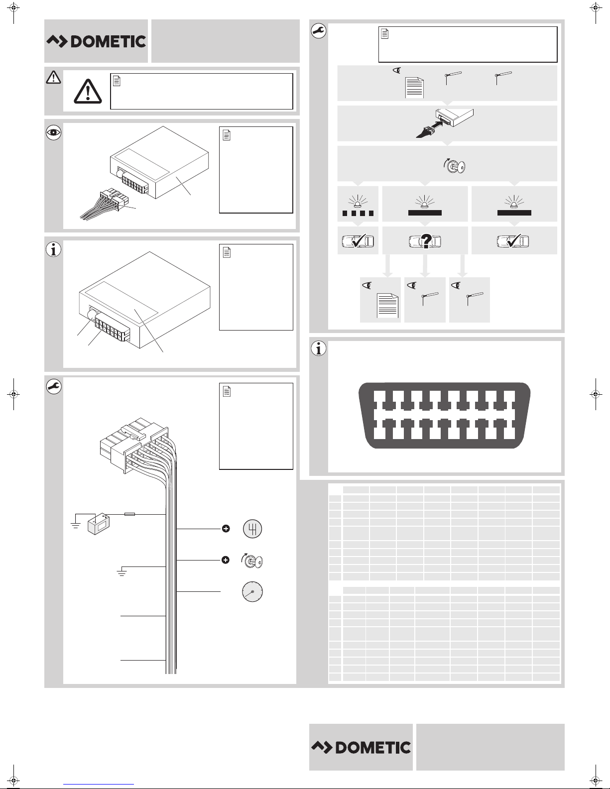
2 Sicherheits- und Einbauhinweise
Siehe Abb. 1
Die folgenden Texte ergänzen die Abbildungen auf dem Beiblatt lediglich. Sie alleine
sind keine vollständigen Einbau- und Bedienhinweise! Bitte beachten Sie unbedingt
die Abbildungen auf dem Beiblatt!
Beachten Sie die vom Fahrzeughersteller und vom Kfz-Handwerk vorgeschriebenen
Sicherheitshinweise und Auflagen!
Der Hersteller übernimmt in folgenden Fällen keine Haftung für Schäden:
•Beschädigungen am Produkt durch mechanische Einflüsse
•Veränderungen am Produkt ohne ausdrückliche Genehmigung vom Hersteller
•Verwendung für andere als die in der Anleitung beschriebenen Zwecke
A•Beachten Sie die geltenden gesetzlichen Vorschriften.
•Installieren Sie das Produkt im Fahrzeuginnenraum.
•Befestigen Sie das Produkt so, dass sie sich unter keinen Umständen (scharfes
Abbremsen, Verkehrsunfall) lösen und zu Verletzungen der Fahrzeuginsassen
führen können.
•Montieren Sie das Produkt nicht im Wirkungsbereich eines Airbags. Sonst besteht
Verletzungsgefahr, wenn der Airbag auslöst.
•Halten Sie einen ausreichenden Abstand zu starken Wärmequellen ein.
•Die Steuerelektronik darf keiner Feuchtigkeit ausgesetzt sein
•Der Anschluss des Produkts an sonstige, von den Vorgaben abweichende Spannun-
gen kann zu Gefahrsituationen führen.
•Nach einer Aktualisierung des Datenprotokolls durch den Fahrzeughersteller funkti-
oniert das Produkt eventuell nicht länger vorschriftsgemäß.
3Lieferumfang
Siehe Abb. 2
Nr. Menge Bezeichnung Artikel-Nr.
1 1 CAN-Bus Interface 9600000428
2 1 Anschlusskabel
CBI200 Can Interface-IO-16S.book Seite 9 Dienstag, 10. Januar 2017 10:36 10