manuals.online logo
Brands
  1. Home
  2. •
  3. Brands
  4. •
  5. Dometic
  6. •
  7. Refrigerator
  8. •
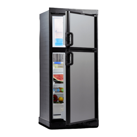
  9. Dometic NDR1492 User manual

Dometic NDR1492 User manual

Other Dometic Refrigerator manuals

Dometic RC 1200 EGP User manual

Dometic

Dometic RC 1200 EGP User manual

Dometic CFX3 25 User manual

Dometic

Dometic CFX3 25 User manual

Dometic RM3663 User manual

Dometic

Dometic RM3663 User manual

Dometic RM 5380 User manual

Dometic

Dometic RM 5380 User manual

Dometic coolmatic CD 30 User manual

Dometic

Dometic coolmatic CD 30 User manual

Dometic COOLMATIC Series User manual

Dometic

Dometic COOLMATIC Series User manual

Dometic CB36 User manual

Dometic

Dometic CB36 User manual

Dometic RH 023 LDAG User manual

Dometic

Dometic RH 023 LDAG User manual

Dometic A30G1 User manual

Dometic

Dometic A30G1 User manual

Dometic 9 SERIES User manual

Dometic

Dometic 9 SERIES User manual

Dometic RMS 8465 User manual

Dometic

Dometic RMS 8465 User manual

Dometic 5 Series User manual

Dometic

Dometic 5 Series User manual

Dometic CFF SERIES User manual

Dometic

Dometic CFF SERIES User manual

Dometic myfridge mf5m User manual

Dometic

Dometic myfridge mf5m User manual

Dometic CRE0050 User manual

Dometic

Dometic CRE0050 User manual

Dometic RML8230 User manual

Dometic

Dometic RML8230 User manual

Dometic RM 2652 User manual

Dometic

Dometic RM 2652 User manual

Dometic CDF2 User manual

Dometic

Dometic CDF2 User manual

Dometic DM20 D CL User manual

Dometic

Dometic DM20 D CL User manual

Dometic RH 569 LD User manual

Dometic

Dometic RH 569 LD User manual

Dometic RM 5310 User manual

Dometic

Dometic RM 5310 User manual

Dometic COOLMATIC CRX PRO 0050T User manual

Dometic

Dometic COOLMATIC CRX PRO 0050T User manual

Dometic MF20-60 User manual

Dometic

Dometic MF20-60 User manual

Dometic RH418NTE User manual

Dometic

Dometic RH418NTE User manual

Popular Refrigerator manuals by other brands

Frigidaire FRS26TS7DW2 Use & care manual

Frigidaire

Frigidaire FRS26TS7DW2 Use & care manual

Fisher Scientific 10ECEEFSA manual

Fisher Scientific

Fisher Scientific 10ECEEFSA manual

Summit FF22BDRSS user manual

Summit

Summit FF22BDRSS user manual

Frigidaire FFRU17B2QWE use & care

Frigidaire

Frigidaire FFRU17B2QWE use & care

Hotpoint ENBGH 19xxx FW operating instructions

Hotpoint

Hotpoint ENBGH 19xxx FW operating instructions

Hitachi R-SG28KPH instruction manual

Hitachi

Hitachi R-SG28KPH instruction manual

AEG S71700TSW0 user manual

AEG

AEG S71700TSW0 user manual

Electrolux ENB3669 Instruction book

Electrolux

Electrolux ENB3669 Instruction book

Electrolux ERN 2930 Instruction book

Electrolux

Electrolux ERN 2930 Instruction book

Beko GNE 60520 X user manual

Beko

Beko GNE 60520 X user manual

Jenn-Air JUR248LBES00 Use & care guide

Jenn-Air

Jenn-Air JUR248LBES00 Use & care guide

LG LRBP1031W - 10 Cu. Ft. Cabinet Depth Bottom Freezer... owner's guide

LG

LG LRBP1031W - 10 Cu. Ft. Cabinet Depth Bottom Freezer... owner's guide

Daewoo RN-33 Series user manual

Daewoo

Daewoo RN-33 Series user manual

Haier RF-8888-174 Service manual

Haier

Haier RF-8888-174 Service manual

Blaupunkt 5CK2 Series user manual

Blaupunkt

Blaupunkt 5CK2 Series user manual

Beko B5RCNE366HG user manual

Beko

Beko B5RCNE366HG user manual

GE TBX21 use and care manual

GE

GE TBX21 use and care manual

Brandt BFC7650SW BFC7650SX instruction manual

Brandt

Brandt BFC7650SW BFC7650SX instruction manual

manuals.online logo
manuals.online logoBrands
  • About & Mission
  • Contact us
  • Privacy Policy
  • Terms and Conditions

Copyright 2025 Manuals.Online. All Rights Reserved.

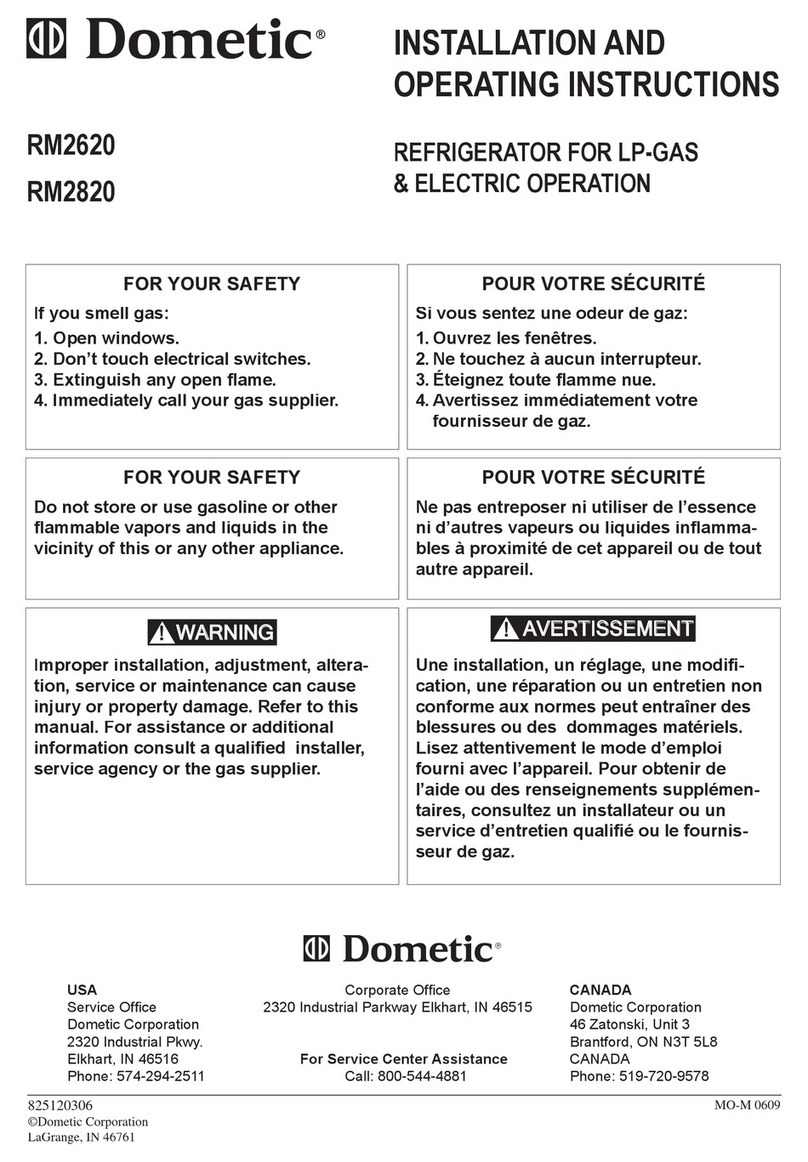
INSTALLATION AND
OPERATING INSTRUCTIONS
REFRIGERATOR FOR LP-GAS AND ELECTRIC OPERATION.
Contents: Page
Installation 4
Operating instructions 8
Maintenance & Service12
Corporate Office
2320 Industrial ParkwayElkhart,IN46515
USA For Service Center AssistanceCANADA
Service OfficeCall: 800-544-4881 DometicDistribution Inc.
The DometicCorporation 866 Langs Drive
509 South Poplar Street Cambridge,Ontario
LaGrange,IN 46761 N3H 2N7 Canada
Phone:219-463-4858 Phone: 519-653-4390
822 70 88-00 (French 3109189.005)
NDR 1492
Automatic Energy Selector
FOR YOUR SAFETY
If you smell gas:
1. Open windows.
2. Don’t touch electrical switches.
3. Extinguish any open flame.
4. Immediately call your gas supplier.
FOR YOUR SAFETY
Do not store or use gasoline or other
flammable vapors and liquids in the
vicinity of this or any other appliance.
WARNING: Improper installation,
adjustment, alteration,service or
maintenance can cause injury or
property damage. Refer to this
manual. For assistance or additional
information consult a qualified
installer, service agency or the gas
supplier.
AVIS
Cet appareil doit être réparé
seulement par un réparateur
autorisé. Modification de
l’appareil pourrait être
extrèmement dangeruse, et
pourrait causer mal ou mort.
NDR1492
Inlet fitting
Burner jet
2 - WAY display panel.
FIG. 2
F
A
B
C
D
E
123
GLEGEND 2-WAY AES Model
1.Main Power Button ON/OFF
2.AES/AUTO/GAS Mode Selector Button
3.Temperature Selector Button
A. AC Mode Indicator Lamp
B.AES/AUTO Mode Indicator Lamp
C. GAS Mode Indicator Lamp
D.CHECK Indicator Lamp
E.Temperature Indicator Lamps
F.Climate Control Switch
G.Low Ambient Switch
FIG. 1
Heaters
Power module
cover
Flexible cord
12 Volt
Terminal block
Flue baffle
Manual gas
shutoff valve
Drain water hose
Protection
cover
Reigniter
3
INSTALLATION
GENERAL INSTRUCTION
This appliance is designed for storage of foods
and storage of frozen foods and making ice.
The refrigerators outlined herein have been design cer-
tified by A.G.A. under the ANSI Z21.19 Refrigerator
Standardforinstallationinamobilehomeorrecreational
vehicle and are approved by the Canadian Gas Asso-
ciation.
The certifications are, however contingent on the instal-
lation being made in accordance with the following in-
structions as applicable.
In the U.S.A., the installation must conform with:
1. NationalFuelGasCodeANSIZ223.1-(latestedition)
2. Manufactured Home Construction and Safety Stan-
dard, Title 24 CFR, Part 3280.
3. Recreational Vehicles ANSI A119.2-(latest edition).
The unit must be electrically grounded in accordance
with the National Electric Code ANSI/NFPA 70-(latest
edition) when installed, if an external alternating current
electrical source is utilized.
4. Any applicable local code.
In CANADA, the installation must conform with:
1. Current CAN/CGA B149 Gas Installation Codes
2. Current CSA Standard Z240.4 GAS-EQUIPPED
RECREATIONALVEHICLESANDMOBILEHOUS-
ING.
3. Where a flexible metal connector is used, it must
comply with the provisions of the current Standard
CAN1-6.10, METAL CONNECTORS FOR GAS
APPLIANCES.
4. Any applicable local code
The unit must be electrically grounded in accordance
with the current CANADIAN ELECTRICAL CODE C22
Parts 1 and 2.
VENTILATION
The installation shall be made in such a manner as to
separate the combustion system from the living space
of the mobile home or recreationalvehicle.Openings for
air supply or for venting of combustion products shall
have a minimum dimension of not less than 1/4 inch.
Proper installation requires one lower fresh air intake
and one upper exhaust vent. The ventilation kits shown
inthisinstructionmanualhavebeencertifiedforusewith
the refrigerator models listed in the table. For "
Certified
Vent System Kits
" see page 15. The ventilation kits
must be installed and used without modification. An
opening toward the outside at floorlevel inthe refrigera-
tor compartment must be provided for ventilation of
heavier-than-airfuelgases.Thelowerventoftherecom-
mended kits is provided with proper size openings.The
flow of combustion and ventilating air must not be ob-
structed.
The lower side vent is fitted with a panel which provides
an adequate access opening for ready serviceability of
the burner and control manifold of the refrigerator.
This should be centered on the back of the refrigerator.
GAS CONNECTION
Hook-up to the gas supply line is accomplished at the
manual gas valve, which is furnished with a 3/8" SAE
(UNF 5/8" -18) male flare connection. All completed
connections should be checked for leaks with soapy
water. ! WARNING
DO NOT use a flame to check for gas leaks.
The gas supply system must incorporate a pressure
regulator to maintain a supplypressure of notmore than
11 inches water column.
When testing the gassupply system attest pressures in
excess of 1/2 psig, the refrigerator and its individual
shutoff valve must be disconnected from thegas supply
piping system.
When testing the gas supply system at pressures less
than or equalto 1/2psig, the appliancemust beisolated
from the gas supply piping systemby closingits individ-
ual manual shutoff valve.
In case detailed instructions on the installation and
connection to the gas supply are required, contact your
dealer or distributor.
ELECTRICAL CONNECTION
120 Volts AC Connection
The refrigerator is equipped with a three-prong (ground-
ing) plug for your protection against shock hazards and
should be plugged directly into a properly grounded
three-prong receptacle. DO NOT cut or remove the
grounding prong from this plug. The free length of the
cord is 2 feet and therefore recommended that the
receptacle be located to the right side of the refrigerator
(viewedfromtherear)andapproximately10inchesfrom
the floor (see FIG.3). This allows easy access through
the vent door.The cord should be routed to avoid direct
contact with the burner cover, flue cover or any other
components that could damage the cord insulation.
12 Volts DC Connection
The refrigerator model NDR 1492 require a continuous
12 volt DC supply (even though 2-way models are
designed to operate on 120 volts AC and gas, a 12 volt
FIG. 3
10"
120 Volt AC
receptacle
4
DC control is required to maintain the automatic energy
system).The connection is made to the positive (+) and
negative (-) terminals of the terminal block on the back
of the refrigerator.(See FIG.1).Correct polarity must be
observed when connecting to the DC supply.
Do not use the chassis or vehicle frame as one of the
conductors. Connect two wires at the refrigerator and
route to the DC supply.
The distance the current must travel from the battery to
the refrigerator dictates the AWG wire size to be used.
Should the wire be too small for the distance, a voltage
drop will result.
Recommended wire sizes are shown below.
Maximumtotalconductorwire lengthin feetand meters.
NDR 1492
2-way
min. wire
size
17 ft. 14 AWG
5 m
27 ft. 12 AWG
8 m
The wires from the battery to the refrigerator must be of
large enough size to handle the load. The connections
must be clean, tight and free from corrosion.
INSTALLING REFRIGERATOR IN
ENCLOSURE
The transport support at the rear of the refrigerator can
be removed ifnecessary for the installation ofthe refrig-
erator in the enclosure.(See figure above).
NOTE: DO NOT install the appliance directly on
carpeting. Carpeting must be removed or
protected by a metal or wood panel be-
neath the appliance which extends at least
full width and depth of the appliance.
Caution: Use care when installing the refrigerator.This
refrigeratoris equippedwith the latest vacuuminsulated
panel technology. These insulating panels are located
on the Top, Back, Bottom, Sides and Doors of the
refrigerator.
If the surface is punctured, loss of insulation will occur,
resulting in poor refrigerator performance.
NOTE: A wood strip must be in place across the upper
opening of the enclosure.The top frame of the refriger-
ator will be anchored to the wood strip with screws,
see FIG.10.
The refrigerator must be installed in a substantial enclo-
sure and must be level.When installing the refrigerator
in the enclosure,all areas within the recess inwhich the
refrigerator is installed must be sealed.
Make sure that there is a complete seal between the
front frame of the refrigerator and the top, sides and
bottom of the enclosure. A length of sealing strip is
applied to the rear surface of the front frame for this
purpose, see FIG. 4. The sealing should provide a
completeisolationoftheappliance’scombustionsystem
from the vehicle interior.
NOTE: Be careful not to damage the sealing strip when
the refrigerator is put in place.
Securing the Refrigerator
Aftertherefrigeratorisputinplace,(ensuringacombus-
tion seal at the front frame), the refrigerator is to be
secured in the enclosure with six screws. The screws
have to be installed in the following order:
STEP1:Twoscrewsinstalledthroughthefrontbase,
which includes the lower front strip installation.
The refrigerator is provided witha lower frontstrip (ship-
pedasaloosepart).Thefrontstripistobeattachedafter
the refrigerator is set into the cutout opening.
1. Install the lower front strip by sliding it under the
bottom hinge plates, as shown in FIG. 5.
FIG. 4
FIG. 5
5
2. Secure the refrigerator and the lower front strip with
two screws: One screw through each hinge.
See FIG 6.
Step 2: Two screws installed in the top frame.
The top decoration panel must be removed from the
refrigerator before the screws can be installed.
Open the doors and remove the four screws thatsecure
the top decoration panel to the top frame. Two screws
are accessible from underneath see FIG.7, the second
two screws that secure the decoration panel to the front
frame are located on each side of the lock retainer.
Carefully tilt the top decoration panel and lift up to
remove from top frame. Be careful not to damage the
circuit board and wires.
Install the two screws in the top frame, the holes are
accessible from underneath.
Seal the opening for the screws with aluminum tape.
Replace the top decoration panel with its four screws.
Be careful not to pinch the wires behind the panel.
STEP 3: Two screws installed in the rear base.
See FIG.8.
Failure to follow the sequence in securing refrigerator in
enclosure can cause leakage between the frame and
cabinet. Any space between the counter, storage area
or ceiling and top of the refrigerator greater den 1-1/2
inchesshouldbe blocked.Theheatproducedat therear
of the refrigerator will become trapped in this space,
making the top of the refrigerator hot and reduce the
efficiency of the refrigerator.
Drain water hose
A hole must be drilled through flooring see FIG.8.
The hole must be drilled in the cut out opening of the
base plate at the rear of the refrigerator. The installer
MUST make sure that the hose does not kinkwhen run
through the floor. Seal around the hose that goes
through thedrilled hole.If a longer hosethan supplied is
required to get the water to drain outside of the vehicle,
the installer will have to supply the extra length of hose.
TESTING LP GAS SAFETY
SHUTOFF
The gas safety shutoff must be tested after the re-
frigerator is connected to LP gas supply.
To test the gas safety shutoff, proceed as follows:
1. Start the refrigerator according to the instructions,
and switch to GAS mode. (See start up instructions).
2. Check that the gas flame is lit and the GAS mode
indicator lamp (C) is on.
3. Closethemanualgasshutoffvalveatthebackofthe
refrigerator. (See FIG. 1).
4. Wait for one minute. The CHECK indicator lamp (D)
should be on and the GAS mode indicator lamp (C)
should be off.
5. Remove protection cover (see FIG. 1) and open the
manual gas shutoff valve. Do not change any button
positions on the control panel. Apply a non-corrosive
commercial bubble solution to the burner jet orifice.
6. No bubbles should appear at the opening of the
burner jet orifice. The presence of bubbles indicates
a defective gas safety shutoff, and service is re-
quired.
7. If no bubbles were present at the burner jet orifice, it
should be rinsed with fresh water. Be careful not to
damage the burner jet orifice. Replace cover and
press the main power ON/OFF button (1) OFF and
back ON. Normal operation of the burner should
return. Allow the burner to operate for a minimum of
five minutes.
FIG. 6
FIG. 7
FIG. 8
Hole for drain water hose
Screws
6
CERTIFIED INSTALLATION
Certified installations require one roof vent and one
lower side vent.
For "
Certified Vent System Kits
" see page 15.
Forfurtherinformationcontactyourdealer ordistributor.
METHODS OF INSTALLATION
The method of installation is shown in FIG. 9. It is
essential that all maximum or minimum dimensions are
strictlymaintainedastheperformanceof therefrigerator
is dependent on adequate flow of air over the rear of the
refrigerator.
NOTE: The upper vent should be centered over
the condenser coil at the back of the refrigerator.
VENTILATION HEIGHTS
Installation with roof Minimum ventilation
vent and lower side vent heights in
Refrigerator Inches mm
NDR 1492 65 1651
CLEARANCES
Minimumclearances in inches to combustiblematerials
are:
G: Top 0
K: Side 0
L: Bottom 0
M: Rear 0
N: See NOTE: Clearance "N" below.
NOTE: Clearance "M" is between the rearmost part of
the refrigerator and the wall behind the refrigerator.
NOTE: Clearance "N" is the distance between the bot-
tom of the lower vent to the roofmaterial.For ventilation
height, see table VENTILATION HEIGHTS
See Figures 9, and 10.
Condenser
Ventilation
height
FIG. 9
13-5/8"
28-5/8"
LOWER VENT CUTOUT
FIG. 10
N
M
G
KK
L
NOTE: Wood Strip
MUST be in place.
7
Overall Recess
Refrigerator Dimensions Minimum Dimensions
Model Height Width Depth Height Width Depth
ABCHWD
inch 59-31/32 37-1/2 26-11/16 59-1/16 36-1/2 24
NDR 1492mm 1523 952 678 1500 927 610
This method of installation and these clearances will give you adequate space for service and proper installation.
OPERATING
INSTRUCTIONS
IMPORTANCE OF LEVELING A
REFRIGERATOR
In an absorption refrigerator system, ammonia is lique-
fied in the finned condenser coil at the top rear of the
refrigerator. The liquid ammonia then flows into the
evaporator (inside the freezer section) and is exposed
to a circulating flow of hydrogen gas, which causes the
ammonia to evaporate, creating a cold condition in the
freezer.
The tubing in the evaporator section is specifically
sloped to provide a continuous movement of liquid am-
monia,flowingdownwardbygravitythroughthissection.
If the refrigerator is operated when it is not level and the
vehicle is notmoving, liquid ammonia willaccumulatein
sections of the evaporator tubing. This will slow the
circulation of hydrogen and ammonia gas, or in severe
cases, completely block it, resulting in a loss of cooling.
Any time the vehicle is parked for several hourswith the
refrigerator operating, the vehicle should be leveled to
prevent this loss of cooling. The vehicle needs to be
leveled only so it is comfortable to live in (no noticeable
sloping of floor or walls).
When the vehicle is moving, the leveling is not critical,
as the rolling and pitching movement of the vehicle will
pass to either side of level, keeping the liquid ammonia
from accumulating in the evaporator tubing.
OPERATION
Beforestartingtherefrigerator,checkthatallthemanual
gas valves are in the ON position. DO NOT forget the
manual shutoff valve on the rear of the refrigerator, see
FIG. 1.
This refrigerator is equipped with an Automatic Energy
Selector (AES) control system, which can automatically
select the most suitable energy source which is avail-
able,either120VoltAC,orLPgasoperation.Thesystem
can be setby the userto be fully automatic, orif desired,
LP gas only.The refrigerator controls will work down to
9.6 volt DC. ! WARNING
Most LP gas appliances used in recreational ve-
hicles are vented to the outside of the vehicle.
When parked close to a gasoline pump, it is
possible that the gasoline fumes could enter
this type of appliance and ignite from the
burner flame, CAUSING A FIRE OR AN EXPLO-
SION.
FOR YOUR SAFETY, when refueling, shut off all
LP gas appliances which are vented to the out-
side.
FIG. 11
Side view View from above
D
H
D
A
B
W
C
8
START UP INSTRUCTIONS
A. A continuous 12 volt DC supply must be available for
the electronic control to function.
B. Press the main power ON/OFF button (1) to the
DOWN position.
C. Press the TEMPERATURE SELECTOR button (3)
until the lamp at the desired setting is illuminated.
AES/AUTO MODE
1. Press the AES/AUTO/GAS mode selector button (2)
to turn ON the AES/AUTO lamp (B). If 120 volts is
available, the AC mode indicator lamp (A) will illumi-
nate indicating AC operation. If 120 volts AC is not
available, the GAS indicator lamp (C) will illuminate,
indicating the control has automatically switched to
the GAS mode.
2. If the CHECK indicator lamp (D) illuminates and the
GASmodeindicatorlamp(C)isoff,thecontrols have
failed to ignite the burner in the GAS mode. GAS
operation may be reset by pressing the main power
ON/OFFbutton(1)totheOFFthenONposition.(See
step 2 under GAS MODE).
3. Press the TEMPERATURE SELECTOR button (3)
until the lamp at the desired position is illuminated.
GAS MODE
1. Press the AES/AUTO/GAS mode selector button (2)
toturnOFFtheAES/AUTOlamp(B).TheGAS mode
indicator lamp (C) will illuminate. Within 45 seconds
the burner should be ignited and operating normally.
2. On the initial refrigerator start-up, it may take longer
than 45 seconds to allow air to be purged from the
gas line. If the gas does not ignite within 45 seconds
the CHECK indicator lamp (D) will illuminate and the
GAS mode indicator lamp (C) will go off.
To reset when the CHECK indicator lamp (D) is
illuminated,pressthemainpowerON/OFFbutton(1)
to the OFF and then ON position.
NOTE: Do not continue to reset GAS operation if the
CHECK indicator lamp continues to be illuminated
after several tries.
3. Press the TEMPERATURE SELECTOR button (3)
until the lamp at the desired position is illuminated.
THERMOSTAT
The thermostat on the refrigerator controls both the gas
and electric operation,thereby eliminatingthe necessity
of resetting each time a different energy source is
employed.
Afterthe initialstart-up,thethermostatshouldbemoved
from "COLDEST" to the desired temperature setting,
usually at mid setting.
TO SHUT OFF THE REFRIGERATOR
The refrigerator may be shut off while in any mode of
operation by pressing the main power ON/OFF button
to the UP (OFF) position.This shuts off all DC power to
the refrigerator, including the interior light.
2 - WAY display panel
3
A
B
C
D
E
12
9
DESCRIPTION OF OPERATING
MODES
AES/AUTO MODE
WhenoperatingintheAES/AUTOmode,theAES/AUTO
mode indicator lamp (B) will illuminate. The control
system will automatically select between AC and GAS
operation with AC having priority over GAS. Either the
AC indicator lamp (A) or the GAS indicator lamp (C) will
illuminate depending on the energy source selected by
thecontrolsystem.Ifthecontrolsystemisoperatingwith
AC energy and it then becomesunavailable, thesystem
will automatically switch to GAS. As soon as AC be-
comes available again the control will switch back to AC
regardless of the status of GAS operation.
GAS MODE
When operating in the GAS mode the AES/AUTO mode
indicatorlamp(B)willbeoffandtheGASmodeindicator
lamp (C) will be illuminated.
This mode provides LP gas operation only. The control
system will activate the ignition system and will attempt
to light the burner for a period of approximately 45
seconds.If unsuccessful,theCHECKindicatorlamp(D)
will illuminate and the GAS mode indicator lamp (C) will
turn off.
To restart GAS operation, press the main power
ON/OFFbutton(1)totheOFFandthenONposition.The
control system will attempt a new 45 seconds ignition
sequence.
If the refrigerator has not been used for a long time or
the LP tanks have just been refilled, air may be trapped
in the supply lines. To purge the air from the lines may
require resetting the main power ON/OFF button (1)
three or four times. If repeated attempts fail to start the
LP gas operation, check to make sure that the LP gas
supplytanksarenotemptyandallmanualshutoffvalves
in the lines are open.If the problem is still notcorrected,
contact a service center for assistance.
If the control is switched to AC operation while the
CHECK indicator lamp is on, it will function properly, but
the CHECK indicator lamp will not go off until the main
power ON/OFF button is pressed to the OFF then ON
position.
LIMP MODE OF OPERATION
This control system contains a feature where it will
continue to operate the cooling system in the event of a
failure of a major operating component. Two different
modes of operation can occur in this category.
If for some reason the display module becomes non
functional,the control systemwill revert to fullautomatic
operation selecting the best energy source available
withAC,GASpriority.Thetemperatureoftherefrigerator
will be maintained at the MID position within normal
temperature tolerances.The power module will continu-
ally attempt to reestablish operation of the display mod-
ule.
The second limp mode of operation will execute when a
failure of the temperature sensing device or associated
electronic circuitry occurs. If this should occur, the con-
trol system will operate on the energy source selected
via the control panel. The cooling unit will run contin-
uously on the selected energy source. The refrigerator
will continue to operate in this mode indefinitely or until
a new sensor is installed and the system is reset.
2 - WAY display panel
3
A
B
C
D
E
12
10