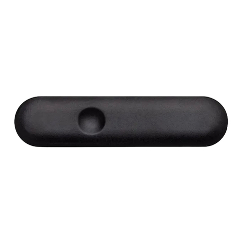
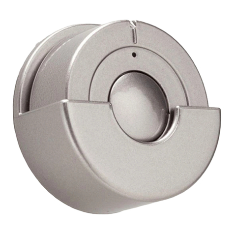
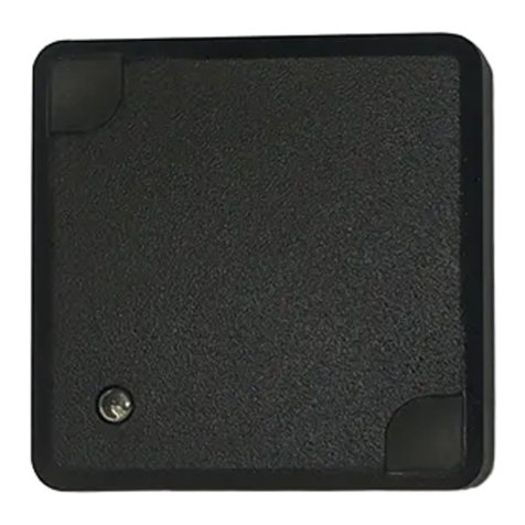
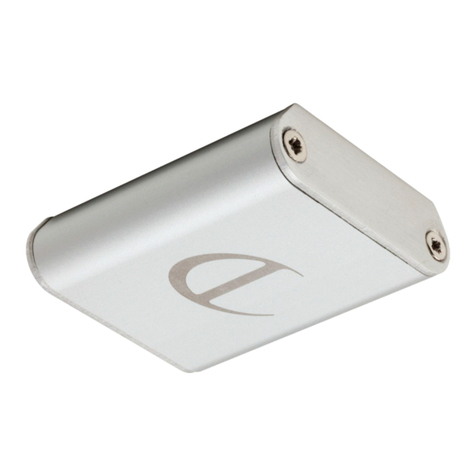
DOMUS LINE DOT Series User manual

DOMUS Line Srl
Via Maestri del Lavoro, 1
33080 PORCIA _ PN _ Italy
phone
fax
e-mail
website
0039 0434 595911
0039 0434 923345
www.domusline.com
MANUALE DI INSTALLAZIONE E USO
INSTALLATION MANUAL
INSTALLATIONSHANDBUCH
MANUEL D'INSTALLATION
MANUAL DE INSTALACIÓN
IT
EN
DE
FR
ES
Ref. 3469900_ r2
DOT
Weitere Infos unter: http://www.lignoshop.de

Apparecchio in classe di protezione III. L'alimentazione deve essere fornita da un alimentatore di sicurezza (secondo la norma EN61347-2-13).
Protection class III device. Power must be supplied by a safe power supply (in accordance with the EN61347-2-13 standard).
Appareil avec classe de protection III. L'alimentation doit être fournie par un transformateur de sécurité (selon la norme EN61347-2-13).
Leuchte mit Schutzklasse III. Die Stromversorgung muss mit einem Sicherheits-Anschlusskabel geliefert werden (nach Richtlinie EN61347-2-13).
Il prodotto deve essere smaltito separatamente dai rifiuti urbani consegnandolo ai centri di raccolta previsti dalla normativa in vigore.
L'adeguata raccolta differenziata contribuisce ad evitare possibili effetti negativi sull'ambiente e sulla salute e favorisce il reimpiego e/o il riciclo
dei materiali. Lo smaltimento abusivo comporta l'applicazione delle sanzioni amministrative previste dalla normativa vigente.
The product must be disposed of separately from urban waste, delivering it to the collection centres established by the prevailing standard.
Adequate sorted waste collection contributes to preventing negative effects on the environment and health and favours reuse and/or recycling
materials. Incorrect disposal of the product implies the application of the administrative sanctions envisaged by the prevailing regulation.
Die Leuchte muss getrennt vom Hausmüll entsorgt und entsprechend der geltenden Richtlinien, an den vorgesehenen Sammelstellen abgegeben werden.
Die angemessene getrennte Sammlung trägt dazu bei, eventuelle negative Auswirkungen auf die Umwelt und die Gesundheit zu vermeiden und die
Wiederverwendung und/oder das Recycling der Materialien zu begünstigen. Die unsachgemäße Entsorgung bringt die Anwendung administrativer Strafen
mit sich, die in den geltenden Richtlinien vorgesehen sind.
Le produit doit être collecté séparément et non jeté avec les déchets ménagers en le portant dans les déchetteries prévues par la réglementation en vigueur.
Un tri sélectif approprié contribue à éviter des possibles effets négatifs sur l'environnement et sur la santé et favorise la réutilisation et/ou le recyclage des
matériaux. L'élimination abusive entraîne l'application des sanctions administratives prévues par la réglementation en vigueur.
Aparato de clase de protección III. La alimentación debe realizarse mediante un alimentador seguro (según la norma EN61347-2-13).
Se debe desechar el producto de forma separada de los residuos urbanos; se lo debe entregar en los centros de recolección previstos por la norma en vigor. La
recolección diferenciada adecuada contribuye a evitar posibles efectos negativos en el medioambiente y en la salud y favorece la reutilización y/o el reciclaje
de los materiales. Si se lo desecha en forma abusiva tendrá como consecuencia la aplicación de sanciones administrativas previstas por la normativa vigente.
Apparecchio per sola installazione in ambiente interno.
Device only for indoor installation.
L'appareil doit être uniquement installé à l'intérieur.
Leuchte nur für die Installation im Innenbereich.
Aparato para un solo uso en un ambiente interior.
Apparecchio idoneo al montaggio in o su superfici normalmente infiammabili.
Device suitable for mounting in or on normally flammable surfaces.
Installation possible de l'appareil dans ou sur des surfaces normalement inflammables.
Leuchte für die Montage in oder auf normal brennbaren Oberflächen.
Aparato apto para el montaje en o sobre superficies normalmente inflamables.
Weitere Infos unter: http://www.lignoshop.de

Min. Ø12 mm
A
E
FD
C
P
Fig 2
Fig 1
Min. Ø12 mm
A
E
FD
C
O
B
Weitere Infos unter: http://www.lignoshop.de

Fig 3
IN
OUT
N
C
ED
F
12Vdc LED luminaire
Converter
MiniPlug distributor
12Vdc set up example
Weitere Infos unter: http://www.lignoshop.de

IN
OUT
G
H
ML
24Vdc LED luminaire
I
Micro24
distributor
Converter
24Vdc set up example
Fig 4
Weitere Infos unter: http://www.lignoshop.de

rispetto al piano di montaggio. Per installazioni con il cavo di
alimentazione in posizione assiale praticare un foro sul piano di montaggio
di ø ≥12mm come indicato nell'esempio in figura 1. In relazione a
specifiche esigenze è tuttavia possibile praticare il foro di uscita del cavo di
alimentazione in altre posizioni purché non pregiudichino l'integrità del
cavo e/o del connettore su di esso installato.
- Per l'installazione dell'apparecchio (A) con biadesivo (B) applicare il
medesimo sul lato posteriore come indicato in figura 1.
- Per l'installazione con supporto (O), fissare il medesimo al piano di
montaggio utilizzando la vite in dotazione (P) e agganciare il DOT come in
figura 2.
- Collegare DOT FW solo ad un alimentatore di sicurezza in tensione
costante a 12Vdc o a 24Vdc (fornito separatamente) e con una potenza
almeno del 10% superiore al carico totale. Per il calcolo del carico totale
controllare il dato di targa stampato sull'etichetta del prodotto.
- Per la connessione ad un alimentatore a 12Vdc (figura 3) inserire il
connettore (C) del cavo di ingresso (IN) di DOT FW ad uno degli slot liberi
del distributore (N) presente sul cavo del secondario del Converter; quindi
collegare il connettore (D) del cavo di uscita (OUT) di DOT FW al
connettore (E) del cavo del distributore MiniPlug (F) il quale è dotato di 12
slot per la connessione di apparecchi di illuminazione a LED funzionanti a
12Vdc.
DATI TECNICI
Tensione di ingresso: 12–24Vdc
Tensione di uscita: 12-24Vdc
Massimo carico applicabile: 36W (con alimentazione a 12Vdc)
72W (con alimentazione a 24Vdc)
AVVERTENZE
La sicurezza è garantita se si seguono queste istruzioni e pertanto è
necessario conservarle. L'installazione può richiedere il coinvolgimento di
personale qualificato. Prima di procedere all'installazione dell'apparecchio
assicurarsi che le condizioni ambientali siano conformi e idonee alle
caratteristiche del prodotto. Prima di ogni operazione sull'apparecchio,
disinserire la tensione di rete.
DOT FW è un interruttore elettronico multifunzione che consente di
comandare apparecchi a LED che funzionano a 12Vdc o a 24Vdc. DOT FW
non può essere installato a contatto con superfici metalliche.
INSTALLAZIONE:
-DOT FW è un apparecchio per installazione in superficie su pannelli in
legno, materiali plastici, granito, ecc. ad eccezione dei materiali metallici
quali ad esempio l'acciaio, l'alluminio, il ferro o simili.
- DOT FW può essere installato con i cavi in posizione assiale o radiale
MANUALE DI INSTALLAZIONE E USO IT
Weitere Infos unter: http://www.lignoshop.de

ATTENZIONE
- Se i cavi flessibili esterni di questo apparecchio vengono danneggiati,
dovranno essere sostituiti dal costruttore o dal suo servizio assistenza.
- DOT FW deve essere collegato direttamente ad un alimentatore di
sicurezza in tensione costante a 12Vdc o a 24Vdc (fornito separatamente)
e non dovrà mai essere collegato ad altri interruttori elettronici o DIMMER
di qualsiasi tipo. Il collegamento di DOT FW ad un interruttore meccanico
tradizionale per ambienti domestici è sconsigliato.
- DOT FW non deve essere installato in prossimità di fonti di calore o nelle
vicinanze di campi elettromagnetici che potrebbero alterare o
comprometterne il funzionamento.
GARANZIA
La garanzia sull'apparecchio è valida solo se alimentato con un alimentatore
fornito da DOMUS Line. Le condizioni generali di garanzia di questo
apparecchio sono disponibili sul sito www.domusline.com
- Per la connessione ad un alimentatore a 24Vdc (figura 4) è necessario
utilizzare il cavo adattatore (G) ed il distributore Micro24 (H) forniti in
confezione. Collegare il cavo di ingresso (IN) di DOT FW al cavo adattatore
(G) e quindi ad uno degli slot liberi del distributore (I) presente sul cavo
del secondario dell'alimentatore; quindi collegare il connettore (L) del
cavo di uscita (OUT) di DOT FW al connettore (M) del cavo del distributore
Micro24 (H) il quale è dotato di 10 slot per la connessione di apparecchi di
illuminazione a LED funzionanti a 24Vdc.
- DOMUS Line garantisce il prodotto solo se alimentato con Converter di
propria fornitura.
COME FUNZIONA DOT FW
- Funzione ON-OFF. L'accensione e lo spegnimento degli apparecchi di
illuminazione collegati a DOT FW avviene mediante un breve contatto
della mano con l'apparecchio.
- Funzione DIMMER e LEVEL MEMORY. Con un tocco prolungato della mano
di DOT FW è possibile regolare l'intensità luminosa degli apparecchi di
illuminazione collegati ad esso (DIMMER). Il livello di luminosità
selezionato verrà memorizzato fino alla successiva regolazione (LEVEL
MEMORY).
MANUALE DI INSTALLAZIONE E USO IT
Weitere Infos unter: http://www.lignoshop.de

INSTALLATION MANUAL EN
axial position drill a ø ≥12mm hole on the installation surface as
illustrated in the example shown in figure 1. In the event of a specific
requirement a power wire exit hole can nevertheless be drilled in other
positions as long as it does not compromise the integrity of the wire
and/or the connector installed on it.
- For the installation of the device (A) with double-sided adhesive (B) to
apply the same on the back side as shown in figure 1
- For installation with support (O) to fix the same to the mounting surface
using the supplied screw (P) and attach the DOT as in Figure 2
- Only connect the DOT FW to a safe power supply with 12Vdc or 24Vdc
stabilised voltage (sold separately) and with power at least 10% higher
than the total load. For the total load calculation check plate data printed
on the product label.
- For connection to a 12Vdc power supply (figure 3) insert the DOT FW
input wire (IN) connector (C) to one of the free slots on the distributor (N)
on the secondary wire of the Converter; then connect the DOT FW output
wire (OUT) connector (D) to the MiniPlug (F) distributor wire connector (E)
which has 12 slots for the connection of 12Vdc LED lighting devices.
- For connection to a 24Vdc power supply (figure 4) an adaptor wire (G) and
the Micro24 (H) distributor provided in the package must be used.
Connect the DOT FW input wire (IN) connector to the adaptor wire (G)
and then to one of the free slots on the distributor (I) on the secondary
TECHNICAL SPECIFICATIONS
Input voltage: 12–24Vdc
Output voltage: 12-24Vdc
Maximum applicable load: 36W (with 12Vdc power supply)
72W (with 24Vdc power supply)
WARNINGS
Safety is guaranteed if these instructions are followed so they must be kept.
Installation may require involving qualified personnel. Before installing the
device ensure that the environmental conditions are in compliance with
and suitable for product characteristics. Before any operation on the device
disconnect mains power.
DOT FW is a multifunction electronic switch which enables control of LED
devices that operate at 12Vdc or 24Vdc. DOT FW cannot be installed in
contact with metal surfaces.
INSTALLATION:
- DOT FW is a device that is installed on the surfaces of wooden panels,
plastic materials, granite, etc.; but not on metal materials such as steel,
aluminium, iron and similar.
- DOT FW can be installed with wires in an axial or radial position with
respect to the installation surface. For installations with the wire in an
Weitere Infos unter: http://www.lignoshop.de

INSTALLATION MANUAL EN
- DOT FW must not be installed near heat sources or in the vicinity of
electromagnetic fields that could alter or compromise operation.
WARRANTY
The warranty on the device is valid only if powered by a power supply
provided by DOMUS Line. The warranty's general terms and conditions for
this device are available at www.domusline.com
wire of the power supply; then connect the DOT FW output wire (OUT)
connector (L) to the Micro24 (H) distributor wire connector (M) which has
10 slots for the connection of 24Vdc LED lighting devices.
- DOMUS Line guarantees the product only if powered with a Converter
supplied by us.
HOW THE DOT FW WORKS
- ON-OFF function. The lighting devices connected to DOT FW are switched
on and off through brief hand contact with the device surface.
- DIMMER and LEVEL MEMORY Function. By touching DOT FW for longer,
you can regulate the light intensity of devices connected to it (DIMMER).
The brightness level selected will be memorised until the next adjustment
(LEVEL MEMORY).
WARNING
- If the external flexible wires of this device are damaged they must be
replaced by the manufacturer or a service centre authorised by the
manufacturer.
- DOT FW must be connected directly to a 12Vdc or 24Vdc stabilised voltage
safe power supply (sold separately) and must never be connected to other
electronic switches or DIMMERS of any type. We advise not connecting
DOT FW to a traditional, mechanical home environment switch.
Weitere Infos unter: http://www.lignoshop.de

INSTALLATIONSHANDBUCH DE
axialer Position eine Bohrung auf der Montagefläche mit ø ≥12 mm
ausführen (Abb. 1). Je nach den spezifischen Anforderungen kann eine
Bohrung für den Austritt des Speisekabels in anderen Positionen
ausgeführt werden, sofern diese nicht die Funktionstüchtigkeit des Kabels
und/oder des installierten Steckverbinders beeinträchtigen.
- Für den Einbau der Vorrichtung (A) mit einem doppelseitigen Klebstoff (B)
dasselbe auf der Rückseite anzuwenden, wie in Abbildung 1 dargestellt.
- Für die Installation mit Unterstützung (O) gleich an der Montagefläche zu
befestigen Sie die mitgelieferten Schraube (P) und befestigen Sie die DOT
wie in Abbildung 2 verwendet wird.
- DOT FW nur an ein Sicherheitsnetzteil mit 12 oder 24 Vdc (separat
bestellbar) anschließen, dessen Leistung mindestens 10 % über der
Gesamtlast liegt. Für die Berechnung der Gesamtleistung kontrolliert man
die Daten auf dem Schildetikett des Produktes.
- Für den Anschluss an ein Netzteil mit 12 Vdc (Abb. 3), den Steckverbinder
(C) des in DOT FW eintretenden Kabels (IN) an einen der freien Steckplätze
des Verteilers (N) am Kabel des Wandlersekundärkreises anstecken.
Danach den Steckverbinder (D) des aus DOT FW austretenden Kabels
(OUT) am Steckverbinder (E) des Kabels des Verteilers MiniPlug (F)
anschließen, der mit 12 Steckplätzen für den Anschluss an die 12 Vdc LED-
Leuchten ausgestattet ist.
- Für den Anschluss an ein Netzteil mit 24 Vdc (Abb. 4) sind das in der
TECHNISCHE DATEN
Eingangsspannung: 12–24 Vdc
Ausgangsspannung: 12–24 Vdc
Anwendbare Höchstlast: 36W (mit 12 Vdc Versorgung)
72W (mit 24 Vdc Versorgung)
HINWEISE
Die Sicherheit wird nur gewährleistet, wenn diese Anweisungen befolgt
werden. Sie sind daher aufzubewahren. Die Installation kann den Einsatz
von Fachpersonal erfordern. Vor der Installation des Gerätes sicherstellen,
dass die Umgebungsbedingungen für die Eigenschaften des Produktes
angemessen und geeignet sind. Vor jeder Arbeit am Gerät, die
Netzspannung trennen.
DOT FW ist ein elektronischer Multifunktionsschalter, der die 12 oder
24 Vdc LED-Leuchten steuert. DOT FW darf nicht mit metallischen
Oberflächen in Kontakt montiert werden.
MONTAGE:
- DOT FW ist ein Gerät, das auf der Oberfläche von Platten aus Holz,
Kunststoff, Granit usw. montiert wird, nicht aber auf metallischen
Materialien wie Stahl, Aluminium, Eisen usw..
- DOT FW kann mit den Kabeln in axialer oder radialer Position zur
Montagefläche installiert werden. Für Installationen mit Speisekabel in
Weitere Infos unter: http://www.lignoshop.de

INSTALLATIONSHANDBUCH DE
- DOT FW ist direkt mit einem Sicherheitsnetzteil mit 12 bzw. 24 Vdc
(separat zu bestellen) zu verbinden und darf niemals an andere
elektronische Schalter oder irgendwelche DIMMER angeschlossen
werden. Der Anschluss von DOT FW mit einem herkömmlichen
mechanischen Haushaltsschalter wird nicht empfohlen.
- DOT FW darf nicht in der Nähe von Hitzequellen oder von
elektromagnetischen Feldern installiert werden, die die Betriebsweise
verändern oder beeinträchtigen könnten.
GARANTIE
Die Garantie auf das Gerät ist nur gültig, wenn es mit einem Netzteil der
Firma DOMUS Line gespeist wird. Die allgemeinen Garantiebedingungen
dieses Gerätes stehen auf www.domusline.com zur Verfügung.
Verpackung enthaltene Adapterkabel (G) und der Verteiler Micro24 (H)
erforderlich. Das in DOT FW eintretenden Kabel (IN) am Adapterkabel (G)
und dann an einen der freien Steckplätze des Verteilers (I) am Kabel des
Netzteilsekundärkreises anstecken. Danach den Steckverbinder (L) des aus
DOT FW austretenden Kabels (OUT) am Steckverbinder (M) des Kabels des
Verteilers Micro24 (H) anschließen, der mit 10 Steckplätzen für den
Anschluss an die 24 Vdc LED-Leuchten ausgestattet ist.
- DOMUS Line garantiert nur für das Produkt, wenn es über einen
firmeneigenen Wandler gespeist wird.
FUNKTIONEN DES GERÄTS DOT FW
- Funktion ON-OFF. Zum Ein- und Ausschalten der an DOT FW
angeschlossenen Leuchten wird die Oberfläche des Geräts kurz mit der
Hand berührt.
- Funktion DIMMER und LEVEL MEMORY Wird DOT FW länger mit der Hand
berührt, kann die Lichtstärke der daran angeschlossenen
Beleuchtungsgeräte (DIMMER) reguliert werden. Die gewählte Lichtstärke
wird bis zur nächsten Regulierung gespeichert (LEVEL MEMORY).
ACHTUNG
- Wenn die Kabel außerhalb der Leuchte beschädigt werden, müssen sie
vom Hersteller bzw. von seinem Kundendienst ausgewechselt werden.
Weitere Infos unter: http://www.lignoshop.de

MANUEL D'INSTALLATION FR
autres matières semblables.
- DOT FW peut être installé avec les câbles en position axiale ou radiale
conformément au plan de montage. - Pour des installations avec le câble
d'alimentation en position radiale, effectuer un trou sur le plan de
montage de ø ≥12mm comme indiqué dans l'exemple sur la figure 1. En
cas d'exigences spécifiques, il est toutefois possible d'effectuer le trou de
sortie du câble d'alimentation dans d'autres positions à condition qu'elles
ne compromettent pas l'intégrité du câble et/ou du connecteur installé
par-dessus.
- Pour l'installation du dispositif (A) avec un adhésif double face (B) pour
appliquer le même sur le côté arrière, comme illustré sur la figure 1.
- Pour une installation avec le support (O) pour fixer le même à la surface
de montage en utilisant la vis fournie (P) et fixer le DOT comme dans la
figure 2.
- Brancher DOT FW uniquement à un transformateur de sécurité avec une
tension constante de 12 Vdc ou de 24 Vdc (fourni séparément) et avec une
puissance supérieure d'au moins 10% de la charge totale. Pour calculer la
charge totale, contrôler les caractéristiques techniques imprimées sur la
plaque du produit.
- Pour le branchement à un transformateur d'une tension de 12 Vdc
(figure 3) insérer le connecteur (C) du câble d'entrée (IN) de DOT FW à l'un
des emplacements libres du distributeur (N) présent sur le câble du
INFORMATIONS TECHNIQUES
Tension d'entrée : 12/24 Vdc
Tension de sortie : 12/24 Vdc
Charge maximale applicable : 36W (avec alimentation de 12 Vdc)
72W (avec alimentation de 24 Vdc)
AVERTISSEMENTS
Il est important pour la sécurité des personnes de suivre ces instructions et
de les conserver. Il peut être nécessaire de faire appel à un personnel
qualifié pour l'installation. Avant de procéder à l'installation de l'appareil
veiller à ce que les conditions environnementales soient conformes et
appropriées aux caractéristiques du produit. Avant toute opération sur
l'appareil, couper la tension du secteur.
DOT FW est un capteur électronique multifonction qui permet de
commander des appareils à LED fonctionnant avec une tension de 12 Vdc
ou de 24 Vdc. DOT FW ne peut pas être installé au contact avec des
surfaces métalliques.
INSTALLATION:
- DOT FW est un appareil conçu pour être installé sur la surface de
panneaux en bois, matières plastiques, granit etc... à l'exception des
matières métalliques comme par exemple l'acier, l'aluminium, le fer ou
Weitere Infos unter: http://www.lignoshop.de

MANUEL D'INSTALLATION FR
- DOT FW must not be installed near heat sources or in the vicinity of
electromagnetic fields that could alter or compromise operation.
WARRANTY
The warranty on the device is valid only if powered by a power supply
provided by DOMUS Line. The warranty's general terms and conditions for
this device are available at www.domusline.com
secondaire du convertisseur ; puis brancher le connecteur (D) du câble de
sortie (OUT) de DOT FW au connecteur (E) du câble du distributeur
10 slots for the connection of 24Vdc LED lighting devices.
- DOMUS Line guarantees the product only if powered with a Converter
supplied by us.
HOW THE DOT FW WORKS
- ON-OFF function. The lighting devices connected to DOT FW are switched
on and off through brief hand contact with the device surface.
- DIMMER and LEVEL MEMORY Function. By touching DOT FW for longer,
you can regulate the light intensity of devices connected to it (DIMMER).
The brightness level selected will be memorised until the next adjustment
(LEVEL MEMORY).
WARNING
- If the external flexible wires of this device are damaged they must be
replaced by the manufacturer or a service centre authorised by the
manufacturer.
- DOT FW must be connected directly to a 12Vdc or 24Vdc stabilised voltage
safe power supply (sold separately) and must never be connected to other
electronic switches or DIMMERS of any type. We advise not connecting
DOT FW to a traditional, mechanical home environment switch.
Weitere Infos unter: http://www.lignoshop.de

MANUAL DE INSTALACIÓN ES
respecto a la superficie de montaje. Para la instalación con el cable de
alimentación en posición axial se tiene que realizar un agujero en la
superficie de montaje de ø ≥12mm como se indica en el ejemplo de la
figura 1. En relación a las necesidades específicas todavía es posible
realizar el agujero de salida del cable de alimentación en otras posiciones
ya que no perjudican la integridad del cable y/o del conector instalado
sobre éste.
- Para la instalación del dispositivo (A) con doble cara (B) aplicar la misma
en el lado trasero como se muestra en la figura 1.
- Para la instalación con el soporte (O) para fijar la misma a la superficie de
montaje utilizando el tornillo suministrado (P) y una el DOT como en la
figura 2.
- Conectar DOT FW solo a un alimentador de seguridad de tensión
constante de 12Vdc o 24Vdc (suministrado por separado) y con una
potencia de al menos 10% superior a la carga total. Para el cálculo de la
carga total comprobar los datos de la placa de características que
aparecen en la etiqueta del producto.
- Para conectar a un alimentador de 12Vdc (figura 3) insertar el conector (C)
del cable de entrada (IN) de DOT FW en uno de los puertos libres del
distribuidor (N) presente en el cable secundario del alimentador; entonces
introducir el conector (D) del cable de salida (OUT) de DOT FW en el
contector (E) del cable de distribución MiniPlug (F) que cuenta con 12
DATOS TÉCNICOS
Tensión de entrada: 12–24Vdc
Tensión de salida: 12–24Vdc
Carga máxima aplicable: 36W (con alimentación a 12Vdc)
72W (con alimentación a 24Vdc)
ADVERTENCIA
La seguridad está garantizada si se siguen estas instrucciones, por lo tanto
es necesario conservarlas. La instalación puede requerir la participación de
personal cualificado. Antes de proceder a la instalación del dispositivo hay
que asegurarse de que las condiciones del lugar sean adecuadas e idóneas
con las características del producto. Antes de manipular el dispositivo
desconectar la tensión de red.
DOT FW es un interruptor electrónico multifunción que permite la
utilización de dispositivos con LED que funcionan a 12Vdc o a 24Vdc.
DOT FW no se puede instalar en contacto con superficies metálicas.
INSTALACIÓN:
- DOT FW es un dispositivo para instalar en superficies de paneles de
madera, materiales plásticos, granito, etc. con la excepción de materiales
metálicos como por ejemplo acero, aluminio, hierro o similares.
- DOT FW se puede instalar con los cables en posición axial o radial
Weitere Infos unter: http://www.lignoshop.de

MANUAL DE INSTALACIÓN ES
ATENCIÓN
- Si los cables flexibles externos de este dispositivo se dañaran, el
constructor o su servicio de asistencia tendrían que sustituirlos.
- DOT FW se tiene que conectar directamente a un alimentador de
seguridad en tensión constante de 12Vdc o 24Vdc (suministrado por
separado) y no se deberá conectar nunca a otros interruptores eléctricos o
DIMMER de cualquier tipo. No se aconseja la conexión de DOT FW a un
interruptor mecánico tradicional para espacios domésticos.
- DOT FW no se debe instalar cerca de fuentes de calor o en la proximidad
de campos electromagnéticos que pudieran alterar o poner en peligro su
funcionamiento.
GARANTÍA
La garantía del dispositivo solo es válida si se utiliza un alimentador
suministrado por DOMUS Line. Las condiciones generales de garantía de
este aparato están disponibles en el sitio web www.domusline.com
puertos para la conexión de dispositivos de iluminación LED que funcionan
con 12Vdc.
- Para conectar a un alimentador de 24Vdc (figura 4) se necesita utilizar el
cable adaptador (G) y el distribuidor Micro24 (H) suministrados en el
paquete. Conectar el cable de entrada (IN) de DOT FW al cable adaptador
(G) y después a uno de los puertos libres del distribuidor (I) presente en el
cable secundario del alimentador; entonces introducir el conector (L) del
cable de salida (OUT) de DOT FW en el conector (M) del cable de
distribución Micro24 (H) que cuenta con 10 puertos para la conexión de
dispositivos de iluminación LED que funcionan con 24Vdc.
- La garantía de DOMUS Line solo es válida si para la alimentación del
producto se utiliza un convertidor de suministración propia.
FUNCIONAMIENTO DE DOT FW
- Función ON-OFF. El encendido y el apagado de los dispositivos de
iluminación conectados al DOT FW se producen mediante un breve
contacto de la mano con la superficie del dispositivo.
-Función DIMMER y LEVEL MEMORY. Al tocar el DOT FW con la mano de
forma prolongada se puede regular la intensidad luminosa de los
dispositivos de iluminación conectados a éste. (DIMMER). El nivel de
luminosidad seleccionado se memorizará hasta que se vuelva a regular
más adelante (LEVEL MEMORY)
Weitere Infos unter: http://www.lignoshop.de

DOMUS Line Srl
Via Maestri del Lavoro, 1
33080 PORCIA _ PN _ Italy
phone
fax
e-mail
website
0039 0434 595911
0039 0434 923345
www.domusline.com
Weitere Infos unter: http://www.lignoshop.de
This manual suits for next models
1
Table of contents
Languages:
Other DOMUS LINE Switch manuals
Popular Switch manuals by other brands

SMART-AVI
SMART-AVI DVR8X8 user manual

Rocket Fish
Rocket Fish RF-WHD200 Quick setup guide

Abus
Abus FU5165 Installation and operating instructions

Black Box
Black Box SW590A-R2 Specifications

BZB Gear
BZB Gear PoE+ Series quick start guide

Suncourt
Suncourt DUCTSTAT TEMPERATURE SENSITIVE SWITCH DS100 Operation instructions