Donaldson Torit STi ODC-TC User manual

This is the safety alert symbol. It is used to alert you to potential personal injury hazards.
Obey all safety messages that follow this symbol to avoid possible injury or death.
13IAF023 (07/14)
Revision 3
English
Master Language
STi Pulse Timer Range
Installation and Operation Manual
Installation, Operation, and Service Information

2
Donaldson Company, Inc.
Regularly check that all equipment is properly selected, sized and operated for the intended use. Discuss any
questions relating to the application, use or maintenance of any Donaldson equipment with your Account Manager.
The delineation of hazardous areas within a work area or facility is beyond the responsibility of Donaldson.
Consequently, the suitability of electrical equipment provided by Donaldson to be installed within these hazardous
areas is also not the responsibility of Donaldson.
Electrical equipment supplied by Donaldson may or may not be suitable for use in a hazardous area. Certain equipment
is suitable for use in certain types of hazardous areas and those equipment are provided with certificates of suitability.
In order to protect your interest, Donaldson strongly recommends that you seek professional advice from qualified
persons regarding the delineation of hazardous areas and the suitability of Donaldson’s equipment within these areas.
The STi timer in its standard form as described in this manual is NOT suitable for hazardous areas. Please consult your
Account Manager for special requirements.
The timer must be installed in compliance with Australian and New Zealand standards. Improper installation may
contribute to conditions in the work area or facility that could result in severe personal injury as well as product and/or
property damage.
PLEASE READ THIS DOCUMENT CAREFULLY PRIOR TO INSTALLATION AND/OR START UP. IT CONTAINS SPECIFIC
PRECAUTIONARY STATEMENTS RELATIVE TO WORKER AND EQUIPMENT SAFETY.
THIS DOCUMENT SHOULD BE READ IN CONJUNCTION WITH THE INSTALLATION, OPERATION AND MAINTENANCE
MANUAL OF THE DUST COLLECTOR UNIT WHOSE REVERSE JET PULSE CLEANING SYSTEM IT IS TO CONTROL.
WARNING, used with the safety alert symbol, indicates a hazardous
situation which, if not avoided, could result in personal injury and
extensive damage.
NOTICE is used to address practices not related to personal injury that
may result in damage to equipment.

3
STi Timer Range
Contents
1 Timer Description ........................................................................................................................................................................ 4
2 Installation Guide ....................................................................................................................................................................... 8
2.1 Mechanical Installation.................................................................................................................................................. 8
2.2 Electrical Installation .................................................................................................................................................... 11
2.2.1 Connections on the master card........................................................................................................................... 11
2.2.2 Connections on the extension card(s) ................................................................................................................. 17
2.3 Pneumatic Installation.................................................................................................................................................. 24
2.3.1 Check connection of solenoid valves to diaphragm valves ............................................................................. 24
2.3.2 Set up on demand cleaning (not required in basic version) ............................................................................ 24
2.3.3 Set up tube cleaner (only required for ODC-TC version) .................................................................................. 24
3 Operation and Site Reprogramming ...................................................................................................................................... 26
4 Programming the Timer............................................................................................................................................................ 30
4.1 Timer Initialisation ......................................................................................................................................................... 30
4.2 Timer Run Screens ........................................................................................................................................................ 31
4.3 Temporarily Stop Filter Media Cleaning .................................................................................................................... 33
4.4 Review Settings ............................................................................................................................................................. 34
4.5 View Service Information............................................................................................................................................. 35
4.6 Request Product Support............................................................................................................................................. 35
4.7 Access Timer Settings.................................................................................................................................................. 36
4.8 Configure Pulse Timing................................................................................................................................................. 36
4.9 Input Handling & Alarms Set Up (not shown in basic version).............................................................................. 39
4.10 ODC Configuration (not shown in basic version) ..................................................................................................... 40
4.11 Tube Cleaner Set Up (only shown in ODC-TC version)............................................................................................ 41
4.12 Manually Test Valve Operation ................................................................................................................................... 42
4.13 View Operational Records ........................................................................................................................................... 43
5 Alarms & Warning Messages................................................................................................................................................. 43
6 General Troubleshooting.......................................................................................................................................................... 46
Appendix 1: Timer Specification Form......................................................................................................................................... 48
Appendix 2: Generalised Wiring Diagram .................................................................................................................................. 49
Appendix 3: Glossary Of Terms..................................................................................................................................................... 50

4
Donaldson Company, Inc.
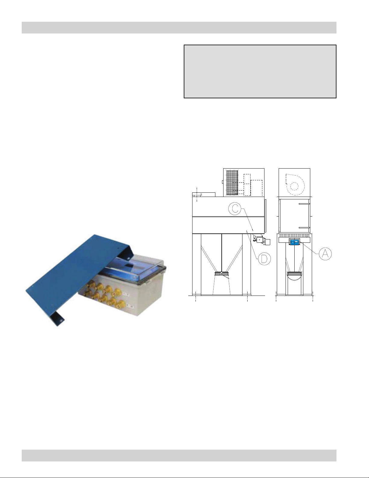
1. TIMER DESCRIPTION
The Solid state pulse Timer intelligent (STi) is the newest
addition to the Donaldson range of timers. This timer
gives a versatile range of options for controlling the
reverse pulse cleaning jets in continuous duty dust
collectors.
The STi timer consists of a master card which is able
to pulse up to 10 solenoid valves. If the timer needs to
control more than 10 valves, the master card needs to
be connected to one or more extension cards using
the supplied CAT5 cable. The master card talks to the
extension cards through differential signalling using the
RS 485 protocol. The addition of each extension card
increases the maximum number of valves that can be
controlled by 10.
At present, three versions are available within the
Donaldson STi timer range:
a. STi timer basic (STi) version. This version fulfills the
basic functions of pulsing the diaphragm valves on
a dust collector and comes with automatic fault
detection features.
b. STi timer with on demand cleaning (STi-ODC) version.
This version monitors the pressure difference
between the clean and dirty air plenums and uses
this information to determine if the filters are clean
or dirty. When the differential pressure crosses the
preset levels, the timer activates cleaning of the filter
media.
c. STi timer with on demand cleaning and tube cleaner
(STi-ODC-TC) version. This version augments on
demand cleaning with its tube cleaner. The tube
cleaner passes a jet of compressed air through
the hose connecting it to the dirty air plenum side
of the collector to dislodge any product that may
accumulate in the tube blocking it. This ensures
reliable measurement of differential pressure
between the dirty and clean air sides of the collector.
The timer is available in two standard configurations. In
the DC configuration these timers drive 24VDC valves
where the input to the timer can be between 110-240
VAC or 24VDC. The timers are also available in a legacy
AC configuration wherein the timers can drive either
110 VAC or 240 VAC solenoids supplied in older dust
collectors, where the input and the output from the timer
are the same (e.g. if the timer is intended to drive 240VAC
solenoid valves then the power input to the timer should
be 240VAC). The timer can be reconfigured to suit special
requirements – please contact your Account Manager to
discuss your specific requirements.
The standard program design of these timers is such
that when only one valve is to be pulsed at any instance
(sequential mode), up to 60 valves can be controlled
by the timer. When more than one valve is to be pulsed
at the same time (parallel mode) there can be up to 4
groups each containing 60 valves. The STi timer can be
custom programmed to allow for a higher number of
valves to be controlled – please contact your Account
Manager to discuss your specific requirements.

5
STi Timer Range
STi basic version STi ODC version STi ODC-TC version
Basic Functional Description The basic version
automatically pulses the
valves at regular intervals
as long as it is powered up
and has not been manually
halted either manually or by
an interrupt signal.
The ODC version pulses the
valves when it detects that
the filters have become dirty
with the option of faster
pulsing when it detects the
filters are significantly dirty.
This version operates
similar to an ODC version
and has additional
hardware for cleaning its
measurement tubes so that
it can accurately detect
when the filters become
dirty.
STANDARD ENCLOSURE PROPERTIES
Polycarbonate UV rated enclosure Y Y Y
Enclosure IP65 rated Y Y Y
BASIC FEATURES
Alphanumeric digital display Y Y Y
Maximum number of valves that can
be connected to the master card
10 10 10
Maximum number of valves that
can be independently controlled in
sequential mode
60 valves 60 valves 60 valves
Maximum number of valves that
can be independently controlled in
parallel mode
Maximum 4 blocks, each
with up to 60 valves
Maximum 4 blocks, each
with up to 60 valves
Maximum 4 blocks, each
with up to 60 valves
Automatic solenoid valve electrical
fault detection facility
Y Y Y
Reporting facility available to identify
if the system is pulsing or is halted
(through General Warnings relay
alarm)
Y Y Y
Manual (continuous) or automatic
(on demand) cleaning facility
available
Continuous Only Both Continuous and On
Demand
Both Continuous and On
Demand
Tube cleaning facility N N Y
Standard pulsing sequence available Y Y Y
Arbitrary pulsing sequence available Y Y Y
Possible range for pulse duration
range
50-990 ms 50-990 ms 50-990 ms
Possible range for interval between
pulses during NORMAL pulsing
1-999 s 1-999 s 1-999 s
Possible range for interval between
pulses during FAST pulsing
N/A 1-99s 1-99s
Possible range for number of cycles
for offline cleaning
0-99 cycles 0-99 cycles 0-99 cycles
Pressure scale in kPa, in H2O and
mm H2O available
N/A Y Y
Forced pulsing facility when cleaning
on demand
N Y Y
Counter for recording total and
session operating hours
Y Y Y

6
Donaldson Company, Inc.
STi basic version STi ODC version STi ODC-TC version
Counter for recording total as well
as number of pulses generated in a
session
Y Y Y
Code protection for settings update Y Y Y
INPUTS AVAILABLE
Power supply requirements 24VDC or 110-240VAC 24VDC or 110-240VAC 24VDC or 110-240VAC
Sensor input monitoring facility
available (interrupts and sensor
inputs are on the same terminal)
N Y Y
No. of sensor inputs that can be
monitored
None 2 (either analogueue or
digital)
2 (either analogue or
digital)
Remote interrupt facility available
(interrupts and sensor inputs are on
the same terminal)
Y Y Y
No. of interrupt switches available 2 2 2
OUTPUTS POSSIBLE
Communication to Extension Cards
via RS 485 bus through CAT5 cable
with twisted pair
Y Y Y
Constant 24VDC output available via
RS 485 bus
Y Y Y
Relay alarm for system health,
triggered off when the timer
identifies that the dust collection
system is no longer able to operate
efficiently
Y Y Y
Relay alarm for warnings, triggered
when the timer identifies that there
might be something wrong with the
dust collection system
Y Y Y
4-20mA current loop for remote
monitoring of differential pressure
N/A Y Y
OPTIONAL EXTRAS (requires additional hardware)
Broken bag detection feature N Y Y
Compressed air header pressure
measurement
N Y Y

7
STi Timer Range
Figure 1: STi master cards (a) basic version and (b) ODC / ODC-TC version. Note the legacy AC version has
different circuitry.
a) STi basic version master cards
b) STi ODC and ODC-TC versions master cards

8
Donaldson Company, Inc.
By default, the order in which the timer pulses the valves
is consecutive (standard pulse sequence) however it is
possible to define an arbitrary pulse sequence during
commissioning. Donaldson’s IAF Engineering Department
can advise if that is required after reviewing all
available facts.
Unless cards are specifically ordered as replacement
parts, the timers are generally supplied in a lockable UV
stabilised, IP65 rated polycarbonate enclosure, which
may or may not have valves fitted directly on to it. Other
enclosures (mild steel/fibre glass/stainless steel) may be
supplied if specifically requested.
2. INSTALLATION GUIDE
2.1 MECHANICAL INSTALLATION
Each STi timer enclosure (whether housing a master
or extension cards) will need to be bolted to either a
mounting bracket for mounting to, or be directly bolted
onto, a suitable vibration free surface on or near the
dust collector.
If the STi timer is supplied with a dust collector, it will
be supplied with the necessary mounting brackets.
Depending on the dust collector unit, the timer may
already be bolted to the dust collector using these
brackets, or the brackets may be supplied loose for
installation by others as close as possible to the
collector on site.
NOTE
Timers ordered as spare parts are not supplied with
any mounting brackets. If you need replacement
bracket, please advise your Account Manager when
you place your order for the timer.
Figure 3 shows the position of the STi timer master
enclosure, marked as (A) and the extension enclosure
as relevant, marked as (B) for different dust collector
models. The figure also shows the location of the
pressure taps for the connection of the clean air and
dirty air sides marked (C) and (D) respectively.
a) Dalamatic Unit Series DU
Figure 3: Location of STi timer master and extension card
enclosure(s) on different Donaldson dust collectors
Figure 2: STi timer enclosure with bracket (bracket
shown is for use with Dalamatic DLMC, DLMV
and DU units)

9
STi Timer Range
b) Dalamatic Cased Unit Series DLMC
c) Dalamatic Insertable Venting Unit Series DLMV
d) Siloair Unit Series VS
e) Downflo Oval Unit Series DFO
f) Powercore Series CPV
Figure 3: Location of STi timer master and extension card
enclosure(s) on different Donaldson dust collectors

10
Donaldson Company, Inc.
Figure 3: Location of STi timer master and extension card
enclosure(s) on different Donaldson dust collectors
Depending on the dust collector unit that the timer
has been configured for, it may be supplied with or
without solenoid valves fitted on the enclosure. If
the timer enclosure if fitted with solenoid valves, it
must not be mounted more than 1.5m away from the
diaphragm valves on the collector.
NOTE
On the DFO series and the Powercore CPC series
units, the master enclosure is normally shipped
loose. The master and extension cards are housed in
a single enclosure on the Powercore VH series unit.
These enclosures should be installed away from the
dust collector by others.
i) Powercore Series VHg) Powercore Series CPC
h) Powercore Series TG

11
STi Timer Range
2.2 ELECTRICAL INSTALLATION
2.2.1 Connections on the master card
Step 1 Access the input/output terminals on the master
card
After opening the STi timer master enclosure door, undo
the dome nut on each corner of the face plate to release
the face plate and the master card PCB. Pull out the PCB
and carefully rotate it inside out to access all the input
and output terminals. Figure 4 identifies the different
terminals on the STi timer master card.
J1 Remote Interrupt/Sensor 1 contacts – digital or
analogue
J2 Remote Interrupt/Sensor 2 contacts – digital or
analogue
J4 External Power supply, 110-240VAC IN
J7 External Power supply, 24VDC IN
J8 RS 485 Power bus to extension cards, 24VDC OUT
J9 RS 485 Communication bus to extension cards
J11 Voltage free digital input to trigger Offline Cleaning
function
J103 Relay contacts for General Warning
J109 Relay contacts for Alarm on Interrupt/Sensor 1
state (not available on basic version)
J111 Relay contacts for Alarm on Interrupt/Sensor 2
state (not available on basic version)
J113 Relay contacts for System Health Alarm
J305 5x Solenoid common contacts
J306 5x Solenoid common contacts + 10 Solenoid active
contacts
J501 Remote dP monitoring contacts, 4-20 mA OUT (not
available on basic version)
Step 2 Check connection of solenoid valves to STi timer
card terminals
The STi enclosure is generally supplied with solenoid
valves fitted to it. In this case, the solenoid valves
will be wired to the J305 and J306 terminals of the STi
master card. The connection of the solenoid valves to
these terminals on the STi master card will need to be
verified. If a connection is missing, please establish this
connection. Each solenoid valve must be connected to
a separate active terminal, however multiple solenoid
valves can be connected to the same common terminal.
+ - E A B + - + - + -
E
-
+
C C CC C
C C CC C 1 2
2D
NC COM NO NC COM NO NC COM NO NC COM NO
J306
SOLENOID ACTIVES
SOLENOID COMMON
J103
GENERAL WARNING
J113
SYSTEM
HEALTH
COMMN. BUS
J9
J8
POWER BUS
24VDC OUT
J7
POWER SUPPLY
24VDC IN
RELAY OUTPUT CONTACTS
J305
SOLENOID COMMON
J11
OFFLINE CLEANING
TRIGGER
J4
POWER SUPPLY
110-240VAC IN
2A G 1D 1A 3 4 5 6 7 8 9 10
J2 J1
CARD VERSION 3.2
J501
REMOTE DP
MONITORING
4-20mA OUT
J111
SENSOR 2
J109
SENSOR 1
LP
HP
DP SENSOR
TUBE CLEANER
J3
UPTO 1A 30VDC or 0.5A 125VAC
4-20mA or 0-10VDC
INTERRUPT/
SENSOR INPUT
CONTACTS
Figure 4: Schematic diagram identifying the different terminals on the STi timer master card 24VDC version.

12
Donaldson Company, Inc.
When the STi enclosure is supplied without solenoid
valves fitted onto it, wiring from the terminals on the
timer to those on the solenoid valves is to be carried out
by others.
Optional Step 3 Connect the extension cards to the
master card
Depending on the dust collector with which the STi
timer is supplied, the master card may be supplied with
additional extension cards. These extension cards may
be supplied fitted in the same enclosure as the master
card, or in separate enclosures.
If a separate enclosure for the extension card is
supplied, a 5m industrial grade CAT5 cable is provided
with the timer to connect the extension card to the
master card through the RS 485 link on the cards
(terminal J8 and J9 on the master card). This cable is
supplied wired to the master card, and is labelled to
identify the different cores of this cable.
If two or more enclosures for the extension cards are
supplied, a 1m industrial grade CAT5 cable is provided
to link the different extension cards, in addition to the
standard 5m cable for linking the first (closest) extension
card to the master card. Additional lengths of the CAT5
cable can always be ordered.
The communication connection from the master card
to the different extension cards can be daisy chained
as shown in Figure 5. Trim the CAT5 cable linking the
extension cards to one another as required.
All extension cards can draw power from the master
card as long as the total length of CAT5 cable linking the
master and the last extension card is less than 20 metres.
If the length is more than 20 metres, then extension cards
should be connected to their own power supply which is
separate to the master card. A suitable heavy duty power
cable should be selected in accordance with AS 3000.
NOTE
If the power source for the extension cards is not
correctly selected, then the valves might not pulse.
Most commonly numerous valves will report solenoid
faults, and the timer may display the Cumulative Valve
Fault error message.
NOTE
The STi timer monitors the current drawn by the coil
of each solenoid valve when it is activated and uses
this information to identify any coil faults.
For this feature to function properly, each solenoid
valve must be terminated at the active and common
terminals of the card that it is connected to, so as to
form a complete current loop.
If the solenoids are not wired in this manner, the timer
will not be able to detect the current drawn by the
coils and will identify that there is an open circuit
fault on the coils.

13
STi Timer Range
STi Master Card
8 7 6 5 4 3 2 1
B A 0v 24v 1 2 3 4 5 6 7 8 9 10 B A 0v 24vC C
8 7 6 5 4 3 2 1
B A 0v 24v 1 2 3 4 5 6 7 8 9 10 B A 0v 24vC C
8 7 6 5 4 3 2 1
B A 0v 24v 1 2 3 4 5 6 7 8 9 10 B A 0v 24vC C
8 7 6 5 4 3 2 1
B A 0v 24v 1 2 3 4 5 6 7 8 9 10 B A 0v 24vC C
STi Extension Card
STi Extension Card
STi Extension Card
STi Extension Card
+ - E A B + - + - + -
E
-
+
C C CC CC C CC C 1 2
2D
NC COM NO NC COM NO NC COM NO NC COM NO 2A G 1D 1A 3 4 5 6 7 8 9 10
CARD VERSION 3.2
TERMINATOR LINK
THROUGH JUMPER JP1
MUST BE INSTALLED
ON THE LAST EXTENSION
CARD IN THE SYSTEM
LP
HP
Figure 5: Schematic
diagram showing the
connection of the RS 485
communication bus from
the STi master card to
multiple extension cards.

14
Donaldson Company, Inc.
Optional Step 4 Activate Offline Cleaning
Depending on the nature of the product being collected
by the dust collector, this product might adhere to the
filter elements when the fan is running. In this case, it
is beneficial to pulse the filter media 3–5 times after the
fan is switched off, to dislodge or remove any product
deposited on the filters.
If this feature is used, a separate hole for connecting the
dust collector fan to the timer has to be drilled in the STi
enclosure. A cable gland matching the size of this drilled
hole, and of at least IP65 rating, must be fitted on this
hole. The position of the hole should be determined such
that there is minimal twisting of the cables inside the STi
enclosure.
To activate this feature, the normally-closed (NC)
voltage-free auxiliary contact of the dust collector fan
must be wired to the terminal J11 of the STi timer, so
that it can detect when the fan has been turned off. The
cable joining these two terminals should enter the STi
enclosure through the hole described in the previous
paragraph.
To deactivate offline cleaning, make sure to bridge the
two contacts of J11.
Optional Step 5 Activate System Health Alarm Relay
Feedback
The STi timer is able to identify if there is a short or an
open circuit on the connections to any of the valves that
are controlled by it. If the timer detects that more than
30% of the solenoid valves are faulty, it identifies that it
will not be able to maintain the differential pressure.
Also, if the differential pressure crosses the Alarm set
point, the timer recognises that it has failed to maintain
differential pressure within the safe operating range.
Finally, if power to the timer is lost, the timer recognises
that the pulse cleaning system has been de-energised
and filters are not being cleaned.
If any of the above conditions are reached, the timer
switches the System Health Alarm Relay. If this relay
is triggered, an electrical notification can be passed
on to the plant control room, so that the operators are
immediately made aware of the issue.
Table 2: System Health Relay Alarm Trigger Map (Relay
ON = System Functioning Properly)
Alarm type Relay On Relay Off
Cumulative Valve
Failure
Valves
functioning OK
Multiple valves
failed
Auto dP
management
Failure
dP below alarm
set point
dP over alarm
set point
Power Power
connected
Power
disconnected
To activate this feature, the input from the plant control
room must be wired to the normally closed (NC) contact
of terminal J111 of the STi timer master card. The relay
contacts are rated up to 1A 30VDC or 0.5A 125VAC.
It might be necessary to drill a hole for the cable to enter
the STi enclosure. If a hole is drilled on the enclosure,
a cable gland matching the size of this drilled hole, and
of at least IP65 rating, must be fitted on this hole. The
position of the hole should be determined such that there
is minimal twisting of the cables inside the STi enclosure.
Optional Step 6 Activate General Warnings Relay
Feedback
The STi timer identifies if a short or an open circuit is
detected in any of the valves controlled by it. If an open
or a short circuit is detected on any of the valves is
detected, the timer triggers this relay.
The STi timer also monitors if the number of extension
cards that it should be connected to it (defined by its
settings which are automatically assessed during POST)
are actually connected to it. If it detects that at any time
during operation the number of actual extension cards
does not match the number that it should be controlling
(indicating a communication fault), it triggers this relay.
The Offline Cleaning feature should not be used in
the dust collector units fitted with a soft explosion
relief membrane. Pulsing of valves in the absence of
the static head generated by the fan can seriously
damage these explosion membranes.

15
STi Timer Range
If the pulsing of the valves has been paused either
manually at the timer or using the remote interrupt
feature, the timer triggers this relay.
The STi timer and the valves need to be serviced at
regular intervals to ensure that they are functioning
optimally. The STi timer has counters that keep track of
the number of hours that the STi timer has been used and
the number of pulses generated by the valves. The timer
triggers this relay when the counters have exceeded
their preset values.
Table 3: General Relay Warnings Trigger Map (Relay ON
= Something may require operator attention)
Warning type Relay On Relay Off
Communication
Error
Unable to
communicate
with all
extension cards
Able to
communicate
with all
extension cards
Individual Valve
Fault
SC/OC detected
on any valve
No valve faults
Pulsing
Notification
Pulsing paused
manually or by
interrupt signal
Pulsing not
paused manually
or by interrupt
signal
Service needed Counters
crossed
threshold
Counters below
threshold
If the relay is triggered, an electrical notification can
be passed on to the plant control room, so that the
operators are immediately made aware of the issue.
To activate these warning features, the input from the
plant control room must be wired to the normally open
(NO) contact of terminal J103 of the STi timer master
card. The relay contacts are rated up to 1A 30VDC or
0.5A 125VAC.
It might be necessary to drill a hole for the cable to enter
the STi enclosure. If a hole is drilled in the enclosure, a
cable gland matching the size of this drilled hole, and
of at least IP65 rating, must be fitted on this hole. The
position of the hole should be determined such that there
is minimal twisting of the cables inside the STi enclosure.
Optional Step 7 Activate Remote Interrupt Function
It is possible to remote interrupt (temporarily pause) the
pulsing of the solenoid valves by passing a digital signal
to the input terminals 1-D or 2-D and G of J1 or J2. When
the interrupt signal is active, the pulsing of the valves is
temporarily paused.
To deactivate the remote interrupt feature, make sure to
bridge the input contacts (preferably 1-D and 2-D) with
the ground contact (G) placed between J1 and J2.
It might be necessary to drill a hole for the cable to
enter the STi enclosure. If a hole is drilled, a cable gland
matching the size of this drilled hole, and of at least IP65
rating, must be fitted on this hole. The position of the hole
should be determined such that there is minimal twisting
of the cables inside the STi enclosure.
Optional Step 8 Activate External Sensor Monitoring and
Coupled Relay Alarm
(Not available in the basic version)
The STi timer is able to monitor the readings of the
external sensors connected to the input terminals J1 or
J2. The timer triggers independent relays if either of the
inputs to these terminals crosses the threshold values
set in the STi software, which can be used as an alarm
to monitor that the dust collection system is working
satisfactorily.
To deactivate the monitoring of external sensors, make
sure to bridge the input contacts (preferably 1-D and 2-D)
with the ground contact (G) placed between J1 and J2.
The relay contacts are rated up to 1A 30VDC or 0.5A
125VAC.
NOTE
If the remote interrupt function is to be activated,
the input terminal must be selected as an interrupt
terminal during software setup.
On the ODC and the ODC-TC versions, the relays
(either J109 or J111) will be triggered when an
interrupt signal is active. This is in addition to the
General Warnings Relay (J103).

16
Donaldson Company, Inc.
Table 4: External Sensor Monitor Relays Trigger Map
(OFF = Sensor within range)
Alarm type Relay On Relay Off
Sensor readout At/beyond
threshold cross
over
Before threshold
cross over
It might be necessary to drill a hole for the cable to
enter the STi enclosure. If a hole is drilled, a cable gland
matching the size of this drilled hole, and of at least IP65
rating, must be fitted on this hole. The position of the hole
should be determined such that there is minimal twisting
of the cables inside the STi enclosure.
Table 5: Terminals for sensor and feedback alarm
connection
Connect to Input
Terminal
Feedback alarm
relay terminals
Sensor Input 1 J1-A if analogue,
or J1-D if digital
and G
J109
Sensor Input 2 J2-A if analogue,
or J2-D if digital
and G
J111
Optional Step 9 Activate Remote Differential Pressure
Reporting
(Not available on the basic version)
Differential pressure across the dirty and clean air sides
of the dust collector can be monitored remotely by an
external device (commonly a PLC, DCS or a SCADA
system) via terminal J501. To activate this feature,
replace the existing terminal link with the external
device, forming a 4-20mA current loop.
The output from terminal J501 is scaled with the
differential pressure read across the dirty and clean air
sides of the dust collector, to the range of 4-20 mA.
Optional Step 10 Check power supply connection to the
tube cleaner
(Only available on the ODC-TC versions)
In the ODC-TC version, the STi enclosure comes fitted
with a tube cleaner on its back panel. This tube cleaner
needs to be connected to the terminal J3 on the STi
master card.
As a standard, the STi timer is generally supplied with
this connection already established. However it is
recommended that the connection of the tube cleaner
to the STi master card be verified before the timer is
switched on. If the connection has come undone or is
missing, please establish this connection.
Step 11 Connect power supply to the STi timer master
card
The STi enclosure is supplied with a M12 hole fitted with
a IP65 rated cable gland for the power supply cable to
enter the enclosure. Use this cable gland to pass the
power supply cable into the STi enclosure.
If the STi timer master box is to run on AC power, connect
the power supply cables to terminal J4. The terminal can
accept between 110 and 240 volt AC supply.
If the timer card is to run on DC power, connect the
power supply cables to terminal J7. The voltage of this
power supply should be regulated at 24 volt DC supply.
NOTE
If the sensor monitoring function is to be activated,
the input terminal must be selected as an alarm
terminal during software setup.
NOTE
The 4-20 mA current loop has been designed to
interface with an external device with an input
impedance of 100Ω. If the input impedance of the
external device is greater, then the range of the
current supplied to the external device will be scaled
down.
No voltage should be applied across terminal J501.
Applying a voltage across this terminal will cause
irreparable damage to the electronic circuitry of the
timer.

17
STi Timer Range
2.2.2 Connections on the extension card(s)
Each STi extension card contains 2 RS 485 bus contacts,
10 solenoid active contacts, 2 solenoid common contacts
and 8 DIP switches as shown in Figure 6.
Step 1 Connect the card to the master and/or other
extension cards
The STi extension cards need to be connected to the
master either directly (when it is the closest extension
card) or through another extension card in a daisy
chained manner as shown in Figure 5. For connecting the
communications bus, connect the supplied CAT5 cable
(already connected to the master or another extension
card) to the A and B terminals of one of the RS 485 bus
contacts on either side of the card.
If the extension card is drawing its power supply from
the master card, connect the two remaining wires of
the CAT5 cable to the 0V and +ve contacts of the RS 485
power bus on the extension card.
If the extension card is independently powered, it might
be necessary to suitably insulate the connection leads
of the remaining wires of the CAT5 cable. Connect the
negative and the positive cables from the independent
power source to the 0V and +ve contacts of the RS 485
power bus. The 0V common must be connected to the
external power supply 0V line.
The STi extension enclosure is supplied with two holes
fitted with IP65 rated cable glands for the RS 485 bus
cables to enter and leave the enclosure. Use these holes
to pass the cables in and out of the enclosure. If there is
no cable leaving the enclosure, then make sure to plug
the hole that is not used.
Figure 6: A standard STi timer extension card (24VDC) together with its
schematic identifying the different terminals
8 7 6 5 4 3 2 1
B A 0v 24v 1 2 3 4 5 6 7 8 9 10 B A 0v 24v
SOLENOID VALVE ACTIVES
C C
COMMONS
DIP SWITCHES
POWER
COMMUNICATION
EIA/TIA 485 BUS
JUNCTION
STi timer extension card
CARD SCHEMATIC IDENTIFYING TERMINALS
EIA/TIA 485 BUS
JUNCTION
POWER
COMMUNICATION
JUMPER 1
RS 485 BUS
JUNCTION
RS 485 BUS
JUNCTION
DIP SWITCHES
JUMPER 1

18
Donaldson Company, Inc.
Step 2 Configure DIP switches
There are a set of 8 DIP switches on the bottom left corner of each extension card. These DIP switches control how
the extension card sends and receives information to and from the STi timer master card, allowing the master to
maintain effective control over the solenoid valves connected to extension card.
Figure 7: Configuration of the DIP switches on the STi timer extension card
Switches 1 to 3 give each extension card a unique binary local address so that it can be individually identified by the
master card. Addresses from 000 to 101 are possible in a standard unit.
Switches 6 to 8 are unused in the standard units, and do not impact extension card configuration.
In Sequential Mode
In Sequential Mode only one valve activates at a time. Switches 4 and 5 are normally unused in Sequential Mode. If
any of these are set to the ON position, the configuration automatically switches to Parallel Mode.
In Parallel Mode
In Parallel Mode multiple valves are activated at once. All cards with the same local address form a bank that pulses
together.
Switches 4 and 5 select the order in which the extension cards send return messages back to the master card (the
block).
Example DIP switch configuration in sequential mode
Example 1 – DIP switch settings for extension cards connected to a master with valves fitted. Valves pulse
sequentially.
Unit Actual Valve No. Software Valve No. Valve Block Switch setting
Master Card Valves 1-10 Valves 1-10 N/A N/A
Extension Card 1 Valves 11-20 Valves 11-20 N/A 000 00 001
Extension Card 2 Valves 21-30 Valves 21-30 N/A 000 00 010
Extension Card 3 Valves 31-40 Valves 31-40 N/A 000 00 011
Extension Card 4 Valves 41-50 Valves 41-50 N/A 000 00 100
Extension Card 5 Valves 51-60 Valves 51-60 N/A 000 00 101
87654321
Block selection
switches
Unused
switches
Parallel mode
8 7 6 5 4 3 2 1
Bank selection
switches
Unused
switches
Sequential mode
ON (1)
OFF (0)
ON (1)
OFF (0)
Bank selection
switches
87654321
Block selection
switches
Unused
switches
Parallel mode
8 7 6 5 4 3 2 1
Bank selection
switches
Unused
switches
Sequential mode
ON (1)
OFF (0)
ON (1)
OFF (0)
Bank selection
switches
Sequential Mode Parallel Mode

19
STi Timer Range
8 7 6 5 4 3 2 1
EXTENSION CARD 1
8 7 6 5 4 3 2 1
EXTENSION CARD 2
8 7 6 5 4 3 2 1
EXTENSION CARD 3
8 7 6 5 4 3 2 1
EXTENSION CARD 4
8 7 6 5 4 3 2 1
EXTENSION CARD 5
Figure 8: DIP switch configuration for Example 1
Example 2 – DIP switch settings for extension cards connected to a master with no valves fitted. Valves pulse
sequentially.
Unit Actual Valve No. Software Valve No. Valve Block Switch setting
Master Card None None N/A N/A
Extension Card 1 Valves 1-10 Valves 1-10 N/A 000 00 000
Extension Card 2 Valves 11-20 Valves 11-20 N/A 000 00 001
Extension Card 3 Valves 21-30 Valves 21-30 N/A 000 00 010
Extension Card 4 Valves 31-40 Valves 31-40 N/A 000 00 011
Extension Card 5 Valves 41-50 Valves 41-50 N/A 000 00 100
Extension Card 6 Valves 51-60 Valves 51-60 N/A 000 00 101
Figure 9: DIP switch configuration for Example 2
Example DIP switch configuration in parallel mode
Example 3 – DIP switch settings for extension cards connected to a master with valves fitted. Valves connected to the
master and extension cards 1 to 3 pulse together as part of block 1.
Unit Actual Valve No. Software Valve No. Valve Block Switch setting
Master Card Valves 1-10 Valves 1-10 1 N/A
Extension Card 1 Valves 11-20 Valves 1-10 2 000 01 000
Extension Card 2 Valves 21-30 Valves 1-10 3 000 10 000
Extension Card 3 Valves 31-40 Valves 1-10 4 000 11 000
8 7 6 5 4 3 2 1
EXTENSION CARD 1
8 7 6 5 4 3 2 1
EXTENSION CARD 2
8 7 6 5 4 3 2 1
EXTENSION CARD 3
8 7 6 5 4 3 2 1
EXTENSION CARD 4
8 7 6 5 4 3 2 1
EXTENSION CARD 5
8 7 6 5 4 3 2 1
EXTENSION CARD 6

20
Donaldson Company, Inc.
Figure 10: DIP switch configuration for Example 3
Example 4 – DIP switch settings for extension cards connected to a master with no valves fitted. Valves connected to
extension cards 1 to 4 pulse together.
Unit Actual Valve No. Software Valve No. Valve Block Switch setting
Master Card None None N/A N/A
Extension Card 1 Valves 1-10 Valves 1-10 1 000 00 000
Extension Card 2 Valves 11-20 Valves 1-10 2 000 01 000
Extension Card 3 Valves 21-30 Valves 1-10 3 000 10 000
Extension Card 4 Valves 31-40 Valves 1-10 4 000 11 000
Figure 11: DIP switch configuration for Example 4
Example 5 – DIP switch settings for extension cards connected to a master with valves fitted. Valves connected to the
master and extension cards 1 and 2 pulse together, and valves on extension cards 3 to 5 pulse together.
Unit Actual Valve No. Software Valve No. Valve Block Switch setting
Master Card Valves 1-10 Valves 1-10 1 N/A
Extension Card 1 Valves 11-20 Valves 1-10 2 000 01 000
Extension Card 2 Valves 21-30 Valves 1-10 3 000 10 000
Extension Card 3 Valves 31-40 Valves 11-20 1 000 00 001
Extension Card 4 Valves 41-50 Valves 11-20 2 000 01 001
Extension Card 5 Valves 51-60 Valves 11-20 3 000 10 001
8 7 6 5 4 3 2 1
EXTENSION CARD 1
8 7 6 5 4 3 2 1
EXTENSION CARD 2
8 7 6 5 4 3 2 1
EXTENSION CARD 3
8 7 6 5 4 3 2 1
EXTENSION CARD 1 EXTENSION CARD 2 EXTENSION CARD 3
EXTENSION CARD 4
8 7 6 5 4 3 2 1 8 7 6 5 4 3 2 1
8 7 6 5 4 3 2 1
Table of contents
Popular Timer manuals by other brands

Theben
Theben TR 608 top2 S Installation and operating instructions

ENFORCER
ENFORCER ENFORCER SA-025EQ manual

XT Racing
XT Racing Mini-Lap owner's manual

Competition Electronics
Competition Electronics Pro Timer CEI 4730 operating manual

BDH
BDH Elkay 3875A-1 Instruction guide

STI
STI LT-1UL quick start guide