Donati CBE Series Operating and maintenance manual

JIB CRANE
MANUAL AND ELECTRIC ROTATION
•“PILLAR” –GBA - CBE SERIES
•“WALL” –GBP - MBE SERIES
- USE INSTRUCTIONS -
INSTALLATION - USE - MAINTENANCE
MARCH 2022
KMAN55MG01
Translated from the original Italian instructions


USO E MANUTENZIONE GRU A BANDIERA SERIE
GBA-GBP-CBE-MBE
INDICE DEL CONTENUTO
1PRELIMINARY INFORMATION.........................................................................1
1.1 Contents and use of the manual ............................................................................................... 1
1.2 Symbols: meaning and use ....................................................................................................... 1
1.3 Collaboration with the user........................................................................................................ 2
1.4 Regulatory compliance............................................................................................................... 2
2DESCRIPTION OF THE MACHINE AND TECHNICAL INFORMATION...........4
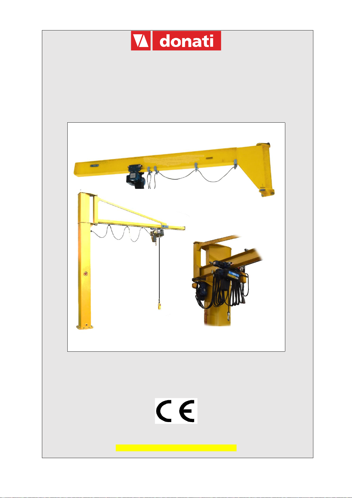
2.1 The jib cranes with manual/electric rotation............................................................................ 4
2.1.1 Intended use - Expected use - Intended purpose .................................................................4
2.1.2 Installation restrictions...........................................................................................................4
2.1.3 La composizione delle gru a bandiera...................................................................................5
2.2 Technical information and service conditions ........................................................................ 9
2.2.1 Regulatory reference framework ...........................................................................................9
2.2.2 Protection and insulation of electrical parts...........................................................................9
2.2.3 Electrical supply.....................................................................................................................9
2.2.4 Ambient use conditions .........................................................................................................9
2.2.5 Noise - Vibration....................................................................................................................9
2.2.6 Use criteria and operating conditions..................................................................................10
2.2.7 GBA-GBP Series - Manual rotation jib cranes: characteristics and technical data.............11
2.2.8 CBE-MBE Series - Electrical rotation jib cranes: characteristics and technical data..........14
2.2.9 GBA/GBP and CBE/MBE: Fixing systems for jib cranes ....................................................16
3SAFETY AND ACCIDENT PREVENTION .......................................................19
3.1 Authorised operator qualifications ......................................................................................... 19
3.2 General safety regulations....................................................................................................... 20
3.3 Safety symbols.......................................................................................................................... 20
3.4 Warnings on residual risks...................................................................................................... 21
3.5 Safety devices and instructions.............................................................................................. 22
3.5.1 Control devices....................................................................................................................22
3.5.2 Safety and emergency devices for GBA- GBP....................................................................22
3.5.3 Safety and emergency devices for CBE e MBE..................................................................23
3.5.4 Warning and notice devices - Signage summary................................................................23
4HANDLING - INSTALLATION - COMMISSIONING.........................................25
4.1 General notes for delivery........................................................................................................ 25
4.2 Packaging, transport and handling......................................................................................... 26
4.2.1 Standard packaging.............................................................................................................26
4.2.2 Transport .............................................................................................................................26
4.2.3 Handling...............................................................................................................................27
4.2.4 Removal of the packaging and/or checking of the crane parts ...........................................28
4.3 Jib crane installation ................................................................................................................ 28
4.3.1 Installer duties and responsibilities......................................................................................28
4.3.2 Preparation of the installation site .......................................................................................29
4.3.3 GBA –CBE: Assembly of the pillar (foundation plate, counterplate, pillar) ........................30
4.3.4 GBP –MBE: Assembly of the bracket (stir-ups, bracket) ...................................................33
4.3.5 GBA/CBE –GBP/MBE: Assembly of the arm .....................................................................36
4.3.6 S profiles channel arm.........................................................................................................38
4.3.7 Mounting of the trolley block inside the S profile channel arm............................................38
4.3.8 Assembly of the electric system with the connector block ..................................................39
4.3.8.1 Commissioning of the rotation limit switch ..................................................................... 41

USO E MANUTENZIONE GRU A BANDIERA SERIE
GBA-GBP-CBE-MBE
II
4.3.8.2 Assembly of the electric system with isolating switch for GBA-CBE pillar-mounted cranes
41
4.3.9 Assembly of the trolley/hoist............................................................................................... 43
4.3.9.1 Assemble of trolley/hoist on the profile S channel arm crane S.....................................43
4.4 Commissioning ......................................................................................................................... 45
4.4.1 Preliminary operations - Adjustments and test runs........................................................... 45
4.4.1 Acceptance test of the jib crane - Suitability for use........................................................... 46
Static test:........................................................................................................................................ 47
4.5 Decommissioning ..................................................................................................................... 47
4.5.1 Storage and preservation of parts ...................................................................................... 47
4.5.2 Resetting after storage ....................................................................................................... 48
5OPERATION AND USE OF THE JIB CRANE .................................................49
5.1 Functions of the jib crane ........................................................................................................ 49
5.1.1 Intended use - Expected use - Intended purpose............................................................... 49
5.1.1 Permitted loads, unpermitted loads.................................................................................... 50
5.1.2 Lifting accessories .............................................................................................................. 50
5.2 Operating conditions ................................................................................................................ 51
5.2.1 Operating environment ....................................................................................................... 51
5.2.2 Zone pericolose e persone esposte ................................................................................... 51
5.2.3 Work area lighting............................................................................................................... 52
5.2.4 Operator.............................................................................................................................. 52
5.2.5 Jib crane capacity............................................................................................................... 53
5.2.6 Manoeuvres: lifting, trolley traverse and arm rotation......................................................... 53
5.2.7 Safety devices..................................................................................................................... 54
5.3 Activating the jib crane............................................................................................................. 54
5.4 Deactivating at the end of work............................................................................................... 55
5.5 Criteri e precauzioni d’uso ....................................................................................................... 56
5.6 Use contraindications............................................................................................................... 57
5.6.1 Unintended and unpermitted use - Predictable and unpredictable incorrect use............... 58
6JIB CRANE MAINTENANCE ...........................................................................60
6.1 Safety precautionary measures............................................................................................... 60
6.2 Qualification of personnel assigned to maintenance............................................................ 62
6.3 Maintenance plan ...................................................................................................................... 66
6.3.1 Daily and routine maintenance ........................................................................................... 66
6.3.2 Frequency and deadlines for maintenance interventions................................................... 67
6.3.3 Test of part and component efficiency................................................................................ 68
6.3.4 Cleaning and lubricating the jib crane ................................................................................ 71
6.4 Adjusting and regulating.......................................................................................................... 72
6.4.1 Adjusting the rotation brake of the crane arm..................................................................... 72
6.5 Troubleshooting........................................................................................................................ 73
6.5.1 Main causes of malfunctions or faults and possible solutions............................................ 73
6.5.2 Personnel authorised to intervene in the event of a failure ................................................ 73
6.5.3 Decommissioning ............................................................................................................... 73
6.6 Disassembly, disposal and scrapping.................................................................................... 73
7SPARE PARTS.................................................................................................74
8CONTROL BOOKLET......................................................................................74

INSTALLATION, USE AND MAINTENANCE
GBA-GBP-CBE-MBE SERIES
1
1 PRELIMINARY INFORMATION
1.1 Contents and use of the manual
This technical publication, identified by the code KMAN55MG00, refers to “Jib cranes, manually/electric
rotated, in GBA-CBE series pillar-mounted model or GBP-MBE series wall-mounted model”, built and put
on the market by the company:
DONATI SOLLEVAMENTI S.r.l.
Via Quasimodo, 17 - 20025 Legnano (MI)
Tel. +39 0331 14811 - Fax +39 0331 1481880
E-mail: [email protected]
www.donaticranes.com
It refers to their “intended use”, to their technical functional and performance characteristics and to the
relevant installation, use and maintenance instructions. It is intended for:
•The supervisor of the factory, workshop, building site
•The staff in charge of transporting, handling and installation of the equipment
•The operators of the jib crane
•The maintenance staff
This manual must be kept by the person in charge of the above mentioned duties in a suitable place, so
that it is always available for consultation and kept in the best possible state.
If the manual is lost or becomes unusable, replacement documentation should be requested directly from
the manufacturer by quoting the code of this manual.
The manufacturer retains the material and intellectual rights of this publication and
forbids the divulgation and duplication, even partial, without prior written permission.
1.2 Symbols: meaning and use
Certain symbols are used in this manual to call the reader’s attention and underline some particularly
important aspects.
The following table shows the list and meaning of the symbols used in the manual.
SYMBOL
MEANING
EXPLANATION, ADVICE, NOTES
Hazard
•
Indicates a hazard with the risk of an accident, including fatal.
•
The failure to comply with the instructions marked with this
symbol may result in a seriously hazardous situation for the
operator’s and/or exposed persons’ safety!
•Carefully follow the instructions!
Warning
•
Represents a warning note of a possible deterioration of the
jib or a personal item of the operator.
•Important warning to pay attention to.
Warning Note
•Indicates a warning or a note on key functions or useful
information.
•
Visual
observation
•Actions to
perform
•
A stylized eye may indicate to the operator that:
a)
He/she needs to make a visual inspection.
b)
He/she must proceed with the operating sequence.
c) A measurement value needs to be read, a warning needs to
be checked, etc.

INSTALLATION, USE AND MAINTENANCE
GBA-GBP-CBE-MBE SERIES
2
1.3 Collaboration with the user
The manual reflects the state of the art at the time the machine was placed on the market and is an integral
part of the machine.
Any supplements to the manual that the manufacturer considers appropriate to send to the users must be
kept together with the manual.
The manufacturer is available to its customers to provide additional information and to consider proposals
for improvement in order to make the manual closer to the needs for which it was prepared.
If the jib crane is sold, the main user is asked to deliver, along with the crane, this manual and the relative
attached documentation (declarations, diagrams, test logbook, etc.).
1.4 Regulatory compliance
GBA-CBE-GBP-MBE jib cranes are designed and produced following the “Essential Safety
Requirements” of Attachment I of the Community Directive 2006/42/CE the crane can be put on the
market with CE Mark and the EC Declaration of Conformity - Attachment II A.
fig. 1 Example of CE Certificate
fig. 2 Example of UKCA Certificate
In addition, GBA-CBE-GBP-MBE jib cranes are in compliance with the following directives:
•Low Voltage Directive 2014/35/EU;
•Electromagnetic compatibility directive 2014/30/EU.
In terms of the contents of this manual the company shall not be held liable in the following cases:
•use of the jib crane not in compliance with national laws on safety and accident prevention
•incorrect selection or set-up of structures on which the crane will be installed
•defects in voltage and the mains supply

INSTALLATION, USE AND MAINTENANCE
GBA-GBP-CBE-MBE SERIES
3
•no or incorrect compliance with the instructions provided in this manual
•unauthorised modifications to the machine
•use by personnel who are not trained or not suitable
To be able to use the warranty, the customer must scrupulously follow the instructions indicated in this
manual, and in particular:
•always operate within the limits of use of the jib crane
•always perform a constant and diligent maintenance
•assign use of the machine to operators with a proven capacity, adequately instructed for the
purpose
•only use the original spare parts indicated by the manufacturer
•The intended use and the configurations of the jib are the only ones allowed.
Do not try to use it ignoring the provided instructions.
•The instructions contained in this manual do not replace but summarise the
obligations to comply with current accident prevention laws.

INSTALLATION, USE AND MAINTENANCE
GBA-GBP-CBE-MBE SERIES
4
2 DESCRIPTION OF THE MACHINE AND TECHNICAL
INFORMATION
2.1 The jib cranes with manual/electric rotation
2.1.1 Intended use - Expected use - Intended purpose
The jib cranes, manually/electric rotated, in GBA-CBE series pillar-mounted model or GBP-MBE series
wall-mounted model, are produced to move goods within the plant.
Jib cranes have three functions:
•they lift the load vertically in space, via a hook on the lifting unit, generally composed of a manual
or electric chain hoist and using accessories suitable for this operation;
•they traverse the load in space, with the assistance of an electric or manual hoist holder trolley,
which runs along the radial axis of the crane arm;
•they rotate the load in space, around the constrained axis of the arm, through a manual push
action of the load using the circular area below, limited by the rotation radius of the arm.
2.1.2 Installation restrictions
The GBA-CBE pillar-mounted jib cranes are intended to be fixed to the ground, the pillar is self-
supporting and can be fixed to the ground using log bolts, on a foundation plinth or in special cases having
checked suitability, also with screw anchors or dowelling.
The GBP-MBE wall-mounted jib cranes are intended to be fixed to an existing structure (pillars, walls,
machine casing, etc), using a system of brackets and staybolts, either with fixing screws or, subject to a
check, with screw anchors or dowelling.
In both cases (pillar-mounted and wall-mounted cranes) the user MUST check, directly
or using specialised staff, the suitability of the surfaces to be fixed on. These surfaces
must guarantee the stability and safety of the crane in all its working conditions,
supporting the lifting operations and the dynamic effects of the tilting momentum and
of the type and speed of lifting

INSTALLATION, USE AND MAINTENANCE
GBA-GBP-CBE-MBE SERIES
5
2.1.3 La composizione delle gru a bandiera
The composition of the jib crane is relatively simple, both in the pillar-mounted version and the wall-mounted
one. Both have a steel structure, the lifting block made up of a chain hoist (electric or manual), the
translation unit formed by a hoist-carrying trolley (electric or push-trolley), a series of accessories (support
brackets, staybolts, foundation plinth, electric unit, etc.).
The GBA-CBE pillar-mounted jib crane consists of a tubular pillar with polygonal section fixed using log
bolts or bolts at the base of appropriate size and an arm which rotates round the axis of the pillar itself.
The GBP-MBE wall-mounted jib crane consists of a bracket support structure which is bolted on the
support structure (fixed to the wall or anchored to a pillar) and an arm which rotates around an axis on the
support bracket.
Both versions are equipped, in most cases, with a chain hoist, fitted with a trolley.
Pillar (GBA-CBE pillar-mounted version):
Made of pressed steel bent in a tubular structure with a polygonal shape it allows a high rigidity and stability
for the crane; it is fixed to the base using a base plate and a system of bolts or log bolts. In the upper part
a couple of plates support the arm of the crane and allow it to rotate (fig. 3).
Support bracket (GBP-MBE wall-mounted version):
It is formed of a couple of plates made of pressed steel; fixed to the wall or anchored to a pillar using
staybolts or screws, it acts as a support to the arm and allows it to rotate (fig. 4).
The rotating arm:
The arm, rotating around its own axis on grazing ball bearings, is formed by a support girder for the sliding
of the hoist-carrying trolley and comes in three basic models for loads from 125 to 2000 kg and ranges up
to 8 m (fig. 5):
•The arm in the channel model “S”: Made with the use of a special section bar made of formed
steel inside which the hoist-carrying trolley slides. The arm is fitted with one or two staybolts which
support the shape and link it to the rising rotating tube. This model features extreme lightness of
movement due to the low inertia from its own reduced weight. This model of the crane is normally
supplied with a push trolley.
•The arm in the staybolted girder model: Made using a double-T formed steel beam girder the
lower flange of which the hoist-carrying trolley slides on. The arm is fitted with one or two staybolts
for the support of the beam which connects it to the rising rotating tube. The crane can be used
with push trolleys, electric trolleys or mechanical ones.
•The arm in the cantilever model: Made using a double-T formed steel beam girder the lower
flange of which the hoist-carrying trolley slides on. The girder is a self-supporting cantilever, without
support staybolts, and it is directly solid, using suitable reinforcement, to the rising rotating tube. It
allows an optimal use of the available space at a height, due to the absence of staybolts. The crane
can be used with push-trolleys, electric trolleys or mechanical ones.

INSTALLATION, USE AND MAINTENANCE
GBA-GBP-CBE-MBE SERIES
6
The braking device of the arm:
It is made up of a clutch system with asbestos-free material, which allows the regulating of the rotating
strain of the arm and ensures its positioning stability (fig. 6).
The electrical system:
It is intended for the electrical input of the hoist and/or trolley (if electric) which slides along the arm of the
crane (fig. 7). It has a connector block, situated on the top of the pillar-mounted jib crane or on the arm
support of the wall-mounted jib crane, for the connector between the line and the festooned cable.
The distribution of energy uses festoon-cable which does not spread flames, generally of the flat type,
sliding on
suitable coasters or sleds that slide the whole way along the arm, inserted in the arm or in a special channel.
Foundation frame with log bolts:
This is supplied on request in the pillar-mounted version, for the fixing of the pillar itself to the base
(foundation plinth) (fig. 8).
Brackets and staybolts unit:
Used for fixing to a pillar in the wall-mounted version, it is available on request. It is fitted with a system of
pressure screws to guarantee the best adherence of the staybolts to the pillar (fig. 9).
fig. 3
fig. 4
fig. 5

INSTALLATION, USE AND MAINTENANCE
GBA-GBP-CBE-MBE SERIES
7
Finishing:
The protection of the steel structures from atmospheric and environmental agents (powders, gas, etc.) is
guaranteed by the treatments which use yellow enamel paint, subject to preparation of the surfaces with
metallic sanding of SA grade.
Lifting and translation unit:
The manually and electricaly rotated jib cranes in the pillar-mounted or wall-mounted version can be
equipped with a chain hoist with the relevant trolley either in electric or manual version.
For the measurements, weights and maximum admissible reactions on the wheels of the trolleys see the
related table in paragraph “Technical data” 0
fig. 6
fig. 7
fig. 8
fig. 9
The conception and construction:
•The manually rotated jib cranes in the GBA-CBE pillar-mounted version and the GBP-MBE wall-
mounted version are designed according to the conception of the modular components which put
together in relation to commercial needs, as well as the standard models always available from the
warehouse, allow the rapid economical realisation of numerous normalised and special executions.
•The base, pillar, bracket and arms components, thanks to their extreme compactness are
assemblable together, so as to guarantee the maximum use of the hook run and, thanks to the
minimal side clearance allow an optimal use of the area in which the jib crane operates.
•The construction uses the most advanced technology which is based on production processes of
high industrialization and allows the realization, using economies of scale, of totally reliable and
technically innovative machines. The high level of quality is guaranteed and controlled by the
company quality system according to the UNI EN ISO 9001:2008 standard.

INSTALLATION, USE AND MAINTENANCE
GBA-GBP-CBE-MBE SERIES
8
Electrical rotation system for arm-version CBE-MBE
This consists of a motoreducer fixed vertically on the lower part of the support bracket, made up of an
epicyclical reducer heat treated, permanently lubricated gear wheels and a conical brake self-braking
motor.
The drive sprocket of the motoreducer fits with the toothed crown integral with the arm which it powers.
Progressive starting-up and braking are ensured by a frequency inverter powered with alternate
monophase current with voltage at 230 V.
The limit switch to limit the rotation of the arm, is of the type with worm screws with 4 contacts. It is fixed to
the rotation stop with 3 screws, inserting the drive shaft of the limit switch in the toothed crown of the arm,
which powers the rotation. The drive shaft is connected to a structure with 4 cams, which by rotating activate
4 switches which work on the low voltage auxiliary circuit.
Motoriduttore
Finecorsa

INSTALLATION, USE AND MAINTENANCE
GBA-GBP-CBE-MBE SERIES
9
2.2 Technical information and service conditions
2.2.1 Regulatory reference framework
In the planning and construction of the manually/electrically rotated jib cranes, pillar-mounted series GBA-
CBE and wall-mounted series GBP-MBE the following standards and principal technical regulations have
been taken into account:
•EN ISO 12100:2010 “General principles for design”
•EN ISO 13849-1:2008 “Safety-related parts of control systems” (where required).
•EN 6020432:2009 “Safety of machinery. Electrical equipment of machines. Requirements for
hoisting machines”
•EN –60529/97 “IP code”
•ISO 4301-1/88 “Cranes and lifting appliances --. Classification”
•FEM 1.001/98 “Rules for the design of hoisting appliances”
•FEM 9.683/95 “Selection of lifting and travel motors”
•FEM 9.755/93 “Measure for achieving safe working periods for motorised serial hoist units
(S.W.P.)””
•FEM 9.941/95 “Graphical symbols for control devices”
•EN 16851/16 “Cranes – Light crane systems”
2.2.2 Protection and insulation of electrical parts
•Rotation motor: Protection IP55 (motor) IP23 (brake); insulation class “F”
•Electrical panel: Protection IP55 - Maximum voltage insulation 1500V
•Push-button panel: Protection IP65 - Maximum voltage insulation 600V
•Collector: Protection IP00 (IP55 upon request) - Maximum voltage insulation 500V
•Limit switch: Protection IP65 - Maximum voltage insulation 300V
•Cables: CEI 20/22 II - Maximum power insulation 450/750V
2.2.3 Electrical supply
•CBE/MBE jib cranes have been designed to be powered with alternating electric current with
maximum three phase voltage of 480V or maximum single phase voltage of 230V
2.2.4 Ambient use conditions
•Operating temperature: minimum - 10°C; maximum + 40°C
•Maximum relative humidity: 80%
•The machine must be installed in a well ventilated area, free from corrosive fumes (acid fumes, salt
mist, etc.).
•It is forbidden to use the machine in an explosive atmosphere or potentially
explosive one or where the use of non-explosive components is required
•Sufficient work spaces must be provided in order to ensure the safety of the
operator and personnel assigned to maintenance.
2.2.5 Noise - Vibration
•For both manual and electrical rotation jib cranes, noise level during functioning is below the
prescribed limits adopted (70 dBA).
•The vibrations produced by the jib crane, during arm rotation, are practically zero and are not
hazardous for the health of the personnel who operates it.
•Excessive noise or vibration may be caused by a fault which must be immediately reported and
eliminated in order not to compromise the reliability of the job crane.

INSTALLATION, USE AND MAINTENANCE
GBA-GBP-CBE-MBE SERIES
10
2.2.6 Use criteria and operating conditions
One of the necessary and indispensible conditions to obtain the complete operating compliance of the jib
crane, for the use it is intended for, as well as excellent and long-lasting operation of the same, consists of
the correct selection of the machine model. This selection must be made based on the real service
performance required as well as the ambient conditions where the crane will operate.
The parameters which must be carefully considered in the choice of jib crane are:
•The capacity: the maximum load weight to lift must be calculated and must not ever be less than
the same.
•The functional dimensions: the height of the trolley beam which determines the hook run of the
hoist, and its jump (jib) must be selected so as to guarantee the functional coverage of the area to
be served in consideration of the surrounding encumbrances.
•Type of travel: manual or electric based on the characteristics of the mass to move.
•Nature of the load: delicate or not determines by its positioning the choice of the most suitable
handling (lifting and travel) speeds. In some cases it is indispensable to use hoists with two speeds
with a slow positioning speed
•Area of use: the jib crane is characterised, by its conception, by intrinsic high elasticity which
becomes even more evident when it is used for handling with loads close to the maximum lifting
capacity and/or with prevalent localisation at the ends of the arm.
•Ambient of use: the jib cranes are intended to be used inside and/or in a covered area, sheltered
from bad weather and wind. Measures must be taken for outdoor use for a suitable surface
treatment (sandblasting - painting) as well as a self-braking system.
•Frequency of use: if use is very high (frequent and/or repeated manoeuvres) with loads close to
the maximum load the consequent fatigue of the operator due to manual handling must be taken
into consideration.
•The correct evaluation of the parameters indicated above, may lead, if they are
close the their limit values, to the need to use a crane with higher performance
characteristics that, once declassed, may ensure greater rigidity and duration.
•The use of an electric trolley instead of a push trolley can also reduce operator
fatigue.

INSTALLATION, USE AND MAINTENANCE
GBA-GBP-CBE-MBE SERIES
11
2.2.7 GBA-GBP Series - Manual rotation jib cranes: characteristics and technical
data
•S Version –manual channel profile version

INSTALLATION, USE AND MAINTENANCE
GBA-GBP-CBE-MBE SERIES
12
•T Version–Manual Underbraced version

INSTALLATION, USE AND MAINTENANCE
GBA-GBP-CBE-MBE SERIES
13
•H Version –Manual overbraced version

INSTALLATION, USE AND MAINTENANCE
GBA-GBP-CBE-MBE SERIES
14
2.2.8 CBE-MBE Series - Electrical rotation jib cranes: characteristics and technical
data
•T Version–Manual Underbraced version

INSTALLATION, USE AND MAINTENANCE
GBA-GBP-CBE-MBE SERIES
15
•H Version –Manual overbraced version

INSTALLATION, USE AND MAINTENANCE
GBA-GBP-CBE-MBE SERIES
16
2.2.9 GBA/GBP and CBE/MBE: Fixing systems for jib cranes
•Brackets and foundations
This manual suits for next models
3
Table of contents
Other Donati Construction Equipment manuals