DONATI SOLLEVAMENTI S.r.l. - Via Quasimodo,17 - 20025 Legnano (MI) - Tel. 0331 14811 - E: dvo.info@donaticranes.com
4
1. – PRELIMINARY INFORMATION
1.1 Contents and recipients of the operating manual
•This technical publication, identified with the code KMAN19MG00, refers to the following products, hereinafter
also referred to as “components”:
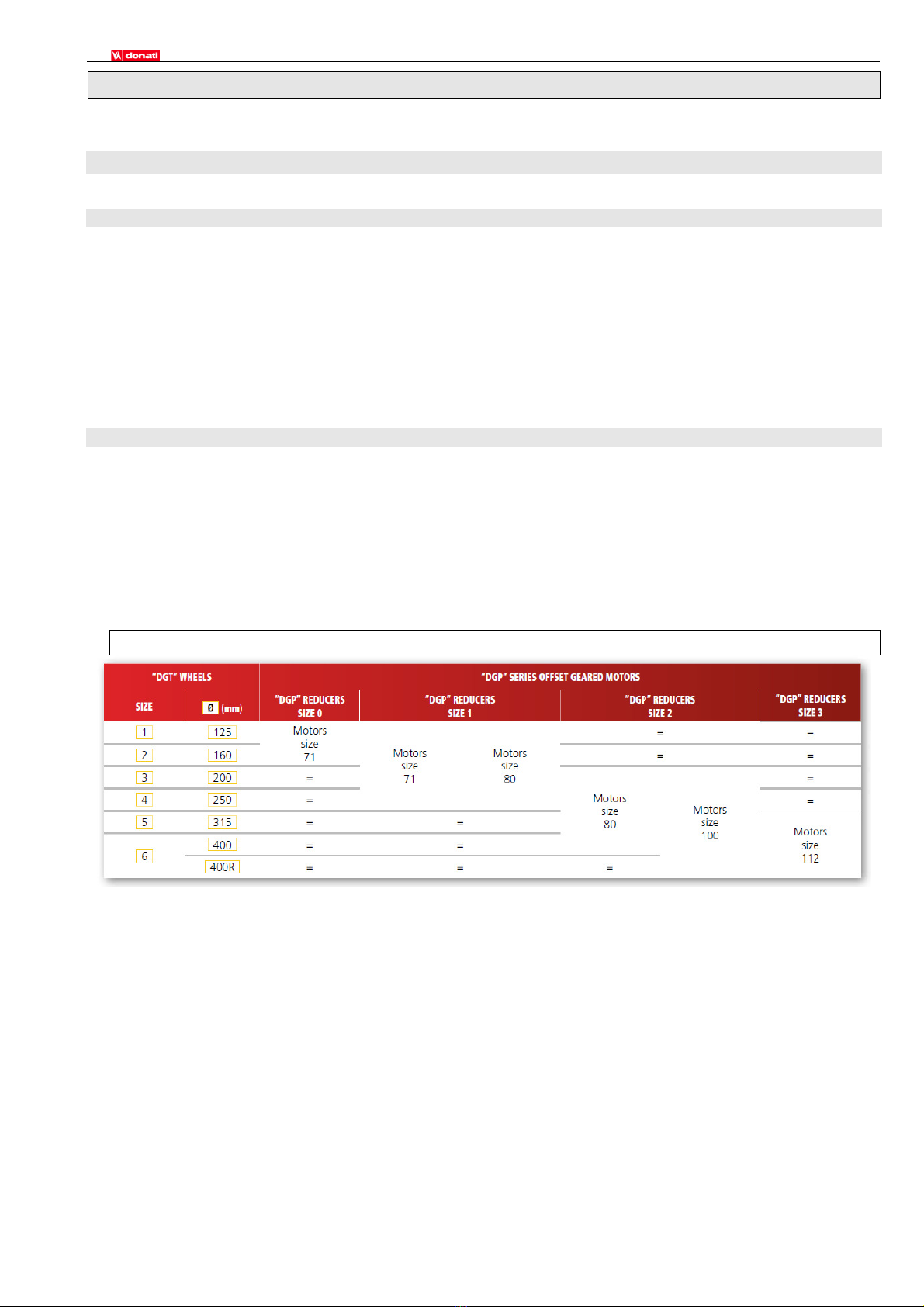
•Drive units, comprising the “DGT” series Wheel Groups, in combination with the “DGP” series Offset
Geared motors;
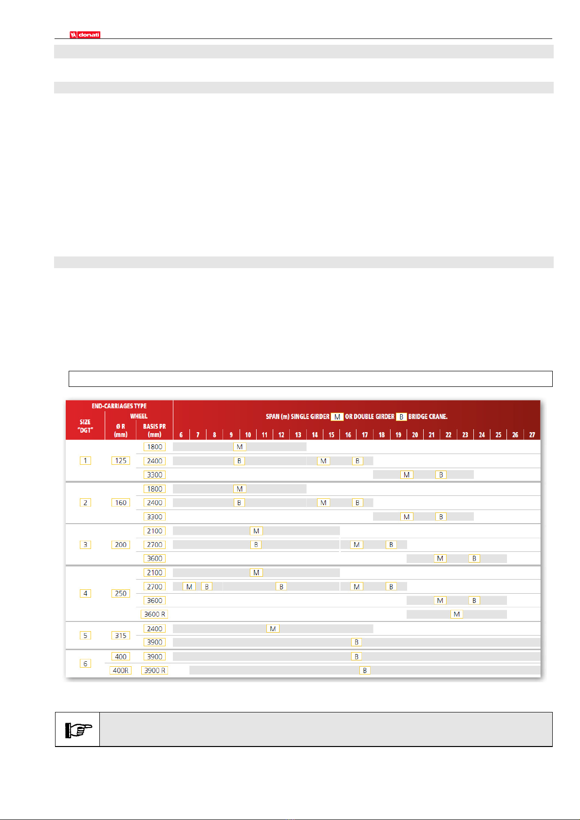
•“DGT” series endcarriages for single girder and double girder bridge cranes;
designed, manufactured and introduced on the market by:
DONATI SOLLEVAMENTI S.r.l.
Via Quasimodo, 17 - 20025 Legnano (MI) - Italy
tel. +39 0331 14811 - fax +39 0331 1481880
e-mail: dvo.info@donaticranes.com - www.donaticranes.com
•In relation to its "intended use," technical and functional specifications, performance characteristics and
installation, use and maintenance instructions, the manufacturer directs its attention at:
•the production plant or work site coordinator
•operators in charge of transport, handling and installation
•personnel charged with maintenance operations
•This operating manual must be kept under the care of a person responsible for the machinery’s operation, in an
appropriate location, so that it is always available for consultation in the best possible state of conservation.
•If this operating should go missing or become damaged, a replacement copy must be ordered directly from the
manufacturer, citing the code of this present operating manual.
•The manufacturer maintains the material and intellectual property rights to this publication
and forbids its dissemination and/or duplication, even partial, without its prior written
consent.
•Copyright© 2018 by DONATI SOLLEVAMENTI S.r.l.
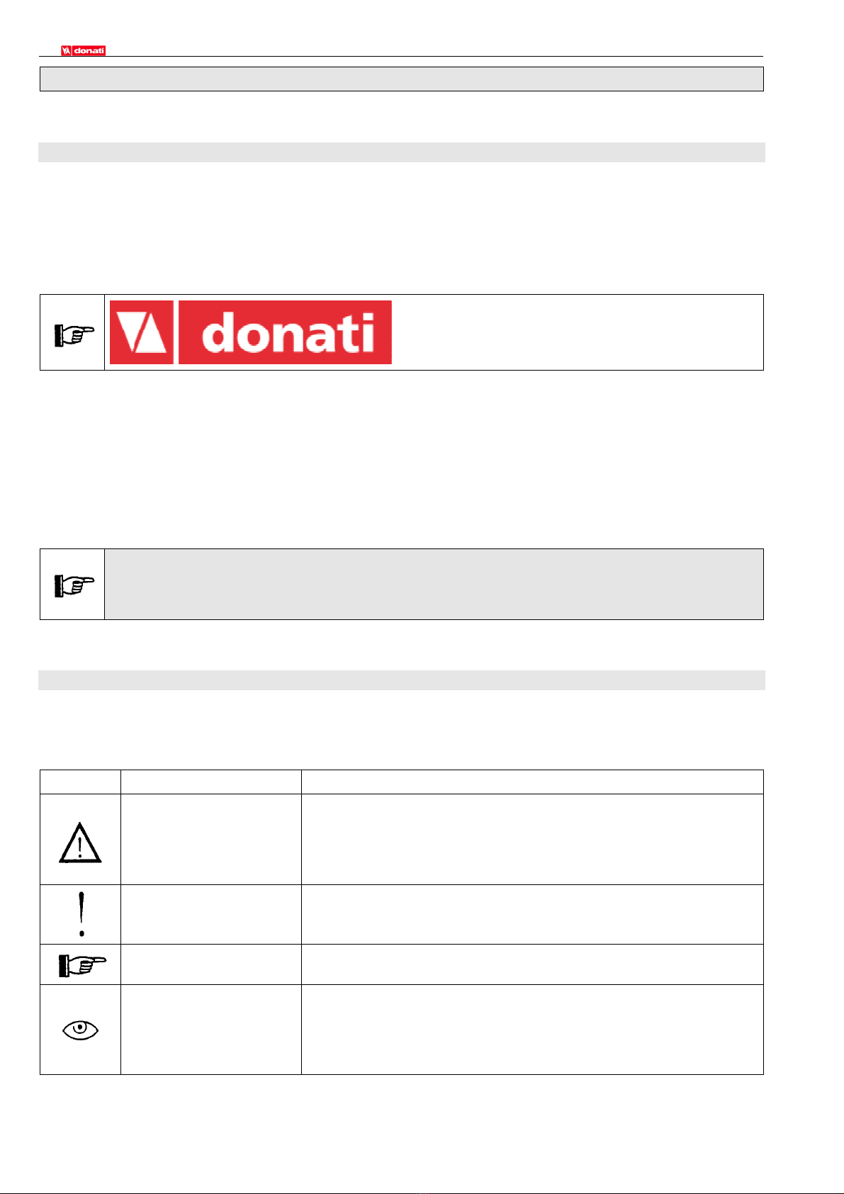
1.2 Symbols: meaning and usage
•This operating manual makes use of various symbols to call the reader’s attention to and emphasize the
importance of certain safety considerations.
The table below provides a list of symbols used in the manual, and their related meaning.
SYMBOL MEANING EXPLANATION, RECOMMENDATIONS, NOTES
Danger
•Indicates danger with the risk of an accident, even death related.
•Failure to respect the safety instructions related to this symbol can
lead to extremely dangerous situations placing the unit’s operator
and/or persons exposed at risk!
•Abide strictly to all safety precautions indicated!
Warning
•Represents a warning notice for the possible deterioration of
components or the operator’s personal belongings.
•Important warning - pay maximum attention.
Caution
Note •Provides information or useful information on key functions.
•Visual control
•Take action
•An eye-shaped symbol tells the reader to:
a) proceed with a visual control check.
b) proceed with the operating sequence.
c) read or take note of a setting or measurement, check an
indication, etc.