Written Date
2010.05.30
Document No.
Change code
0
File/Reference
Operation Manual.DOC
Page
(9/21)
DONGAH ELECOMM R&D CENTER
All rights are reser ed.
4. System Management
4.1 In Normal operation, all rectifiers in the shelf supply power to the outputs.
4.1.1 Shelf (DIRS-4110)
In Normal operation, AC input(s) should be within specifications and output fuses must be active.
4.1.2 Control Module (DIRC-4)
The Control Module front panel LED is GREEN in Normal operation (RED indicates a failure).
4.1.3 Rectifier Module (DRM-440H44R0)
Within the shelf, each Rectifier Module front panel LED is GREEN in Normal operation (RED indicates
5. Rectifier System
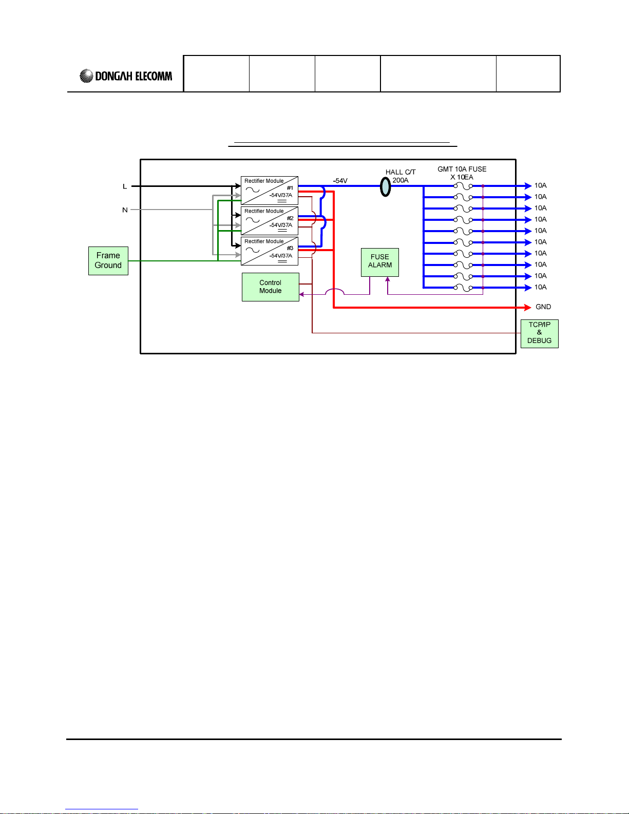
5.1 Rectifier System Operating Principles
5.1.2 System Components
The Rectifier System is composed of up to (3) DRM-440 Rectifier Modules, a DIRC-4 Control Module,
and a Power Distribution block. The system accepts an 8 -264VAC, single-phase input, filters, rectifies,
and delivers a well-regulated, factory-set 4V output at 111A (with 3 rectifiers at 37A each).
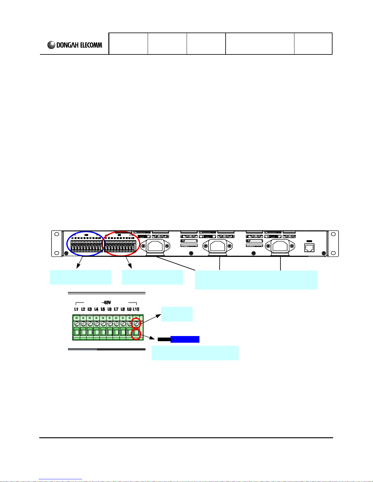
screw-lock into (2) 10-terminal block load connectors (one for 4V and one for GND) at rear of the shelf.
Designed to efficiently and reliably power a customer's system, the DIRS-4110 System includes protection
and alarm features, hot-swappability, solid current-sharing, and system monitoring via TCP/IP and SNMP.
5.1.1 Rectifier System Basic Operation
The Rectifier System receives commercial AC power to the Shelf, and internally to the Controller and
Rectifier Modules. With intelligent control, the AC is rectified and DC power is delivered through
a failure).
Output distribution includes (10) GMT fuses visible at the front of the shelf, with output connections that
fuse-protected output terminals of the shelf.