Programming
8Digit
Card Code
Registered Card
065,00678
Operation Using Control Cards Using IR Remote
Use ADD and/or DELETE card (see desired operation below).
Use ADD and/or DELETE card (see desired operation below) or wait until green
LED turns off.
1. Present ADD card (green LED flashes).
2. Present new card (reader beeps).
3. Repeat step 2 with additional new cards.
4. Present ADD card or wait until green LED turns off to exit programming.
1. Present ADD card (green LED flashes).
2. Present DELETE card (reader beeps).
3. Present DELETE card once for each second of time before door will release
(i.e. swipe DELETE card 3 times for three seconds).
4. Wait until green LED turns off to exit programming.
press “#”, followed by the 6 digit password (green LED on).
Manufacturer’s default is “000000”.
press “ ” or wait until green LED turns off.
This function is NOT programmable using IR Remote.
This function is NOT programmable using IR Remote.
NOT applicable.
NOT applicable.
Enter programming mode
Exit programming mode
Enroll one or more new
cards one at a time.
Record card #’s on log
sheet for future reference.
1. Present DELETE card (green LED flashes).
2. Present card to be deleted (reader beeps).
3. Repeat step 2 with additional cards to be deleted.
4. Present DELETE card or wait until green LED turns off to exit programming.
1. Enter programming mode with remote (See above).
2. Press “6” (green LED flashes).
3. Enter 8digit card number, 3 digit FC, 5 digit CC.
4. Repeat step 2 and 3 with additional cards to be deleted.
5. Press “ ” or wait until green LED turns off to exit programming.
1. Enter programming mode with remote (See above).
2. Press “4” TWICE. THIS CANNOT BE UNDONE.
Delete one or more cards
one at a time.
1. Enter programming mode with remote (See above).
2. Press “5” (green LED flashes).
3. Enter 3 digit release time (i.e. “001” for 1 second,
“030” for thirty seconds, “255” for 255 seconds).
Change door release time
(1 - 255 seconds)
Create new ADD and
DELETE control cards.
1. Enter programming mode with remote (See above).
2. Press “7” (green LED flashes).
3. Present first new card - this is new ADD card (reader beeps).
4. Present second new card - this is new DELETE card (reader beeps).
Note: Discard OLD ADD and DELETE control cards.
1. Enter programming mode with remote (See above).
2. Press “1” (green LED flashes).
3. Enter new 6 digit password (reader beeps).
Change Password.
1. Present DELETE card 5 times (reader beeps).
2. Present ADD card 5 times (long beep). THIS CANNOT BE UNDONE.
Delete ALL cards.
1. Present ADD card TWICE (green LED flashes).
2. Present FIRST card in the block of cards (reader beeps).
3. Present LAST card in the block of cards (reader beeps).
4. Present ADD card or wait until green LED turns off to exit programming.
Enroll a block of new
cards.
Record card #’s on log
sheet for future reference.
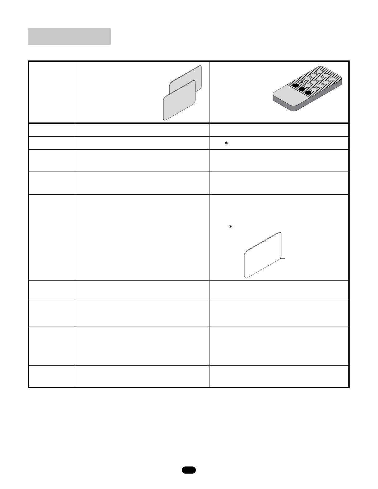
ADD card
DELETE card
123
456
789
0
#
EXIT
DEL REV
ADD CALL
DoorKing Part Numbers
1524-331, 1524-080
card reader only card reader with lighted enclosure
2
1524 065-M-8-15


