manuals.online logo
Brands
  1. Home
  2. •
  3. Brands
  4. •
  5. DoorKing
  6. •
  7. Test Equipment
  8. •
  9. DoorKing 1514-130 User manual

DoorKing 1514-130 User manual

120 S. Glasgow Avenue
Inglewood, California 90301 U.S.A.
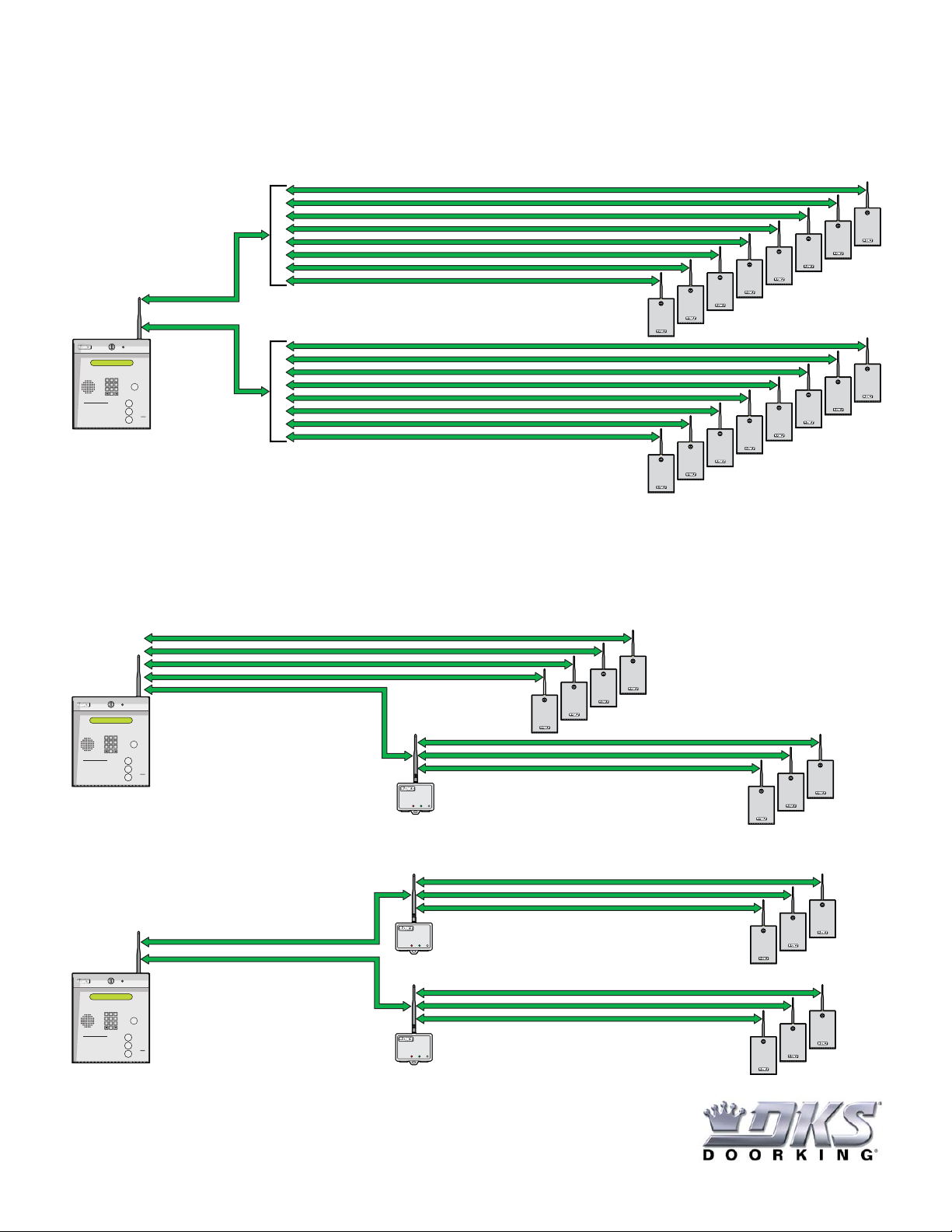
The DoorKing Wireless Test Range Kit allows easy testing of a wireless signal between a DKS telephone entry system (Models 1833, 1835, 1837
and 1838) and DKS access control devices such as a card readers, keypads, etc.
The test kit can be used to measure the wireless signal loss between a telephone entry system and access control device in desired positions
BEFORE they are installed. Making sure the 2 systems have a good signal between them to communicate successfully in their desired positions.
The test kit can also be used to measure the wireless signal between a new access control device to be installed with an existing telephone entry
system that has already been installed.
WIRELESS TEST RANGE KIT
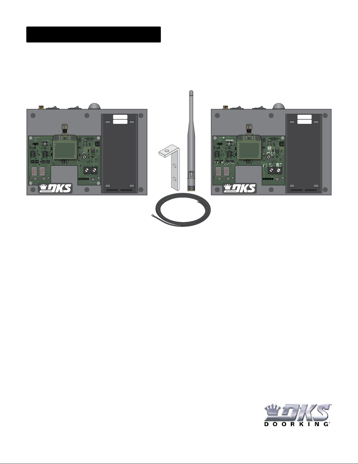
Test Units Adjustments and Switches
Test Units LED Descriptions
Place test units where telephone entry system (BASE unit) and access control device (REMOTE unit) will be installed. Test signal, move test
units around if necessary to achieve LED display of less than 75.
New Installation Option (NO Entry Systems have been Installed yet)
Use existing wireless baseboard already installed in telephone entry system (Do not use BASE unit for this signal testing). Place REMOTE unit
where new access control device will be installed. Test signal, move REMOTE unit around if necessary to achieve LED display of less than 75.
Existing Installation Option (Telephone Entry System has been Installed)
Step 1: Test signal from access control device location (REMOTE unit) to repeater location (BASE unit).
DO NOT power up any other wireless devices during this test.
Step 2: Test signal from repeater location (REMOTE unit) to telephone entry system location (BASE unit).
DO NOT power up any other wireless devices during this test.
If Installing a Repeater
Test Units Start-Up
REMOTE UNIT: Must be positioned where access
control device is installed.
BASE UNIT: Must be positioned where telephone entry
system is installed. Base unit adjustments and switches
are the same as remote unit.
Long Range Antenna Note: Locate antennas 12-15ft above ground to prevent any vehicles (trucks, buses etc.) from interfering with
wireless signal.
TEST SIGNAL Note: Only the 2 wireless units that are
being signal tested should have power. DO NOT power
up any other wireless devices during testing or LED
display signal may NOT be accurate.
1. Turn Power ON at both units. Note: Keep power turned OFF when units are not in use to conserve battery life.
2. Choose antenna switch setting - dome antenna or long range antenna. Note: Long range antenna can be mounted away from test unit.
3. Set RF ID to same setting on both units.
3. Set RF Channel to same setting on both units.
4. Set RF Range to MAX (full clockwise) on both units.
5. Press program button on both units. LEDs will light (see LED descriptions below).
RF Strength LED (Green LED is the goal):
GREEN LED: reliable signal. LED display reads 75db or less. Good signal for reliable communication.
YELLOW LED: marginal signal. LED display reads 75db - 79db (not recommended), should find a better signal for reliable communication.
RED LED: unacceptable signal. LED display reads 80db or more, must find a better signal for reliable communication.
RF Lost LED: Will remain OFF when signal is detected. Will turn ON when no signal is detected.
RF Sync LED: Will intermittently blink BLUE when test units are communicating. Will remain OFF when no signal is detected.
1514-065-A-8-14 Copyright 2014 DoorKing, Inc. All rights reserved.
0
F
E
D
C
B
A
9
8
7
6
2
1
A
9
8
7
6
2364-010
RF LOST RF SYNC RF
STRENGTH
0
F
E
D
C
B
A
9
8
7
6
2
1
A
9
8
7
6
236
4-
0
1
0
RF L
OST
RF
S
YN
C
RF
S
TREN
G
TH
2369-081
REMOTE
0
F
1
1
2364-010
RF LOST RF SYNC
0
F
1
1
236
4-
0
1
0
RF L
OST
RF
S
YN
C
2369-080
BASE
Program
Button
Switch
Antenna Power Dome Antenna
Long Range
Antenna
Connection
Long Range
Antenna
Long Range
Antenna
Mount
RF
Range
RF ID RF Channel
RF Strength LED
RF Sync LED
POWER:
4 C Alkaline
Batteries
RF
Lost
LED
LED Display
Long Range
Antenna
Cable Extension
DoorKing Part Number
1514-130
Test each wireless signal between the telephone entry system location and each access control device locations individually. Turn OFF all power to
any devices not being tested or signal interference could occur. Up to 24 access control devices can be directly wirelessly connected to the
telephone entry system. See Wireless System Layout and Start-Up guide for COMPLETE information. Your system layout can vary from this
example.
If the signal loss reads 75-85db between the test units, then a repeater can be used between the 2 devices to make the signal loss read less than
75db. Repeater can also help route wireless signal around buildings and obstructions. Test 2 devices at a time and turn OFF all other devices not
being tested or signal interference could occur. Up to 3 access control devices can be routed through a repeater if necessary. See Wireless
System Layout and Start-Up guide for COMPLETE information. Your system layout can vary from these examples.
Test Signal Loss Between Telephone Entry System and
Each Access Control Device Location
When a Repeater is Needed
DoorKing Part Number
1514-130
8
7
7
8
8
9
9
4
4
5
5
6
6
1
1
2
2
3
3
0
0
OPER
OPER
WXYZ
WXYZ
TUV
TUV
PQRS
PQRS
MNO
MNO
JKL
JKL
GHI
GHI
DEF
DEF
ABC
ABC
SP
SP
CALL
Z
A
TELEPHONE ENTRY SYSTEM
HOLD TO SCAN
OPERATINGINSTRUCTIONS
Use “A to Z” Buttons to Locate
Nameand Code Number on Display.
Namesare In Alphabetical Order.
T
o Call, Enter Code Number on
Keypador Press “Call” Button. If
Lineis Busy, Press “#” or “Call” to
HangUp. Try Again.
E
nteron Open Display and Tone.
1.
2.
3.
Relay 2/Wiegand 2 direct wireless communication (board addresses 3-10)
Note: Zones addresses must be used if more than 8 boards are used.
Telephone Entry
System Location
Telephone Entry
System Location
Telephone Entry
System Location
System Layout Schematic
910
7
6
5
4
3
16
Relay 1/Wiegand 1 direct wireless communication (board addresses 11-18)
Note: Zones addresses must be used if more than 8 boards are used.
Wireless
Tracker Expansion
Board Locations
Wireless
Tracker Expansion
Board Locations
17 18
15
14
13
12
11
DoorKing Technical Support: 1-800-826-7493
3 Boards MAX Through a Repeater
Direct Wireless Communication
Multiple repeaters can be used in the wireless system.
Relay 2/Wiegand 2
Relay 2/Wiegand 2
7
7
8
8
9
9
4
4
5
5
6
6
1
1
2
2
3
3
0
0
OPER
OPER
WXYZ
WXYZ
TUV
TUV
PQRS
PQRS
MNO
MNO
JKL
JKL
GHI
GHI
DEF
DEF
ABC
ABC
SP
SP
CALL
Z
A
TELEPHONE ENTRY SYSTEM
HOLD TO SCAN
OPERATINGINSTRUCTIONS
Use “A to Z” Buttons to Locate
Nameand Code Number on Display.
Namesare In Alphabetical Order.
T
o Call, Enter Code Number on
Keypador Press “Call” Button. If
Lineis Busy, Press “#” or “Call” to
HangUp. Try Again.
E
nteron Open Display and Tone.
1.
2.
3.
Wireless
Tracker Expansion
Board Locations
6
5
4
3
9
8
7Wireless
Tracker Expansion
Board Locations
Wireless
Repeater
Relay 1/Wiegand 1 Note:
Another communication line can be
wirelessly connected if desired.
Relay 1/Wiegand 1 Note:
Another communication line can be
wirelessly connected if desired.
3 Boards MAX Through a Repeater
7
7
8
8
9
9
4
4
5
5
6
6
1
1
2
2
3
3
0
0
OPER
OPER
WXYZ
WXYZ
TUV
TUV
PQRS
PQRS
MNO
MNO
JKL
JKL
GHI
GHI
DEF
DEF
ABC
ABC
SP
SP
CALL
Z
A
TELEPHONE ENTRY SYSTEM
HOLD TO SCAN
OPERATINGINSTRUCTIONS
Use “A to Z” Buttons to Locate
Nameand Code Number on Display.
Namesare In Alphabetical Order.
T
o Call, Enter Code Number on
Keypador Press “Call” Button. If
Lineis Busy, Press “#” or “Call” to
HangUp. Try Again.
E
nteron Open Display and Tone.
1.
2.
3.
5
4
3
Wireless
Repeater
8
7
6
Wireless
Repeater
Wireless
Tracker Expansion
Board Locations
Wireless
Tracker Expansion
Board Locations

Popular Test Equipment manuals by other brands

Tektronix, Inc. TLS 216 user manual

Tektronix, Inc.

Tektronix, Inc. TLS 216 user manual

LeCroy LC Series Operator's manual

LeCroy

LeCroy LC Series Operator's manual

Kewtech EZYPAT instruction manual

Kewtech

Kewtech EZYPAT instruction manual

Kenwood CS-3035 instruction manual

Kenwood

Kenwood CS-3035 instruction manual

Kikusui TOS5200 Setup guide

Kikusui

Kikusui TOS5200 Setup guide

Tektronix 2213 instruction manual

Tektronix

Tektronix 2213 instruction manual

Oakton EcoTestr pH 2 operating instructions

Oakton

Oakton EcoTestr pH 2 operating instructions

Alcofind AF-50 instruction manual

Alcofind

Alcofind AF-50 instruction manual

Mecon Zone-Lux Operating	 instruction

Mecon

Mecon Zone-Lux Operating instruction

Testboy TV 470 operating instructions

Testboy

Testboy TV 470 operating instructions

Sunlight Electronics Laboratory 7116C Operation manual

Sunlight Electronics Laboratory

Sunlight Electronics Laboratory 7116C Operation manual

farmex BHT-1 owner's manual

farmex

farmex BHT-1 owner's manual

Pockethernet Pockethernet manual

Pockethernet

Pockethernet Pockethernet manual

CDP Blow & Go 4500 manual

CDP

CDP Blow & Go 4500 manual

NOYAFA NF-8601 instruction manual

NOYAFA

NOYAFA NF-8601 instruction manual

Clinton FL-20A instruction manual

Clinton

Clinton FL-20A instruction manual

ETCR ETCR2000E Plus manual

ETCR

ETCR ETCR2000E Plus manual

Tektronix MSO4000B Series user manual

Tektronix

Tektronix MSO4000B Series user manual

manuals.online logo
manuals.online logoBrands
  • About & Mission
  • Contact us
  • Privacy Policy
  • Terms and Conditions

Copyright 2025 Manuals.Online. All Rights Reserved.