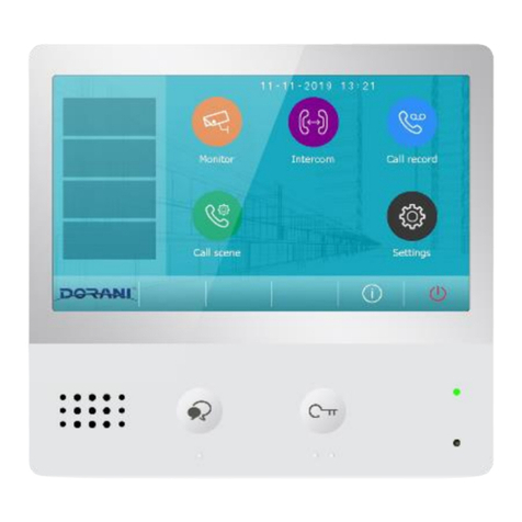
DORANI DORVT User manual

DORANI TOUCH
VIDEO INTERCOM SYSTEM
USER MANUAL
MODEL: DORVT
2 WIRE SYSTEM

2
FEATURES
-True Touch Screen functionality
-2 x Door station connectivity
-4 x Internal Monitors connectivity (SEE N TE)
-Picture Memory Recording (with addition of Micro SD Card)
-2 Door Releases from the 1 Door Station (with D RV )
-Auto Divert to Mobile when not at home (with D RVT05/06 Installed)
-2 Camera - CCTV Viewing from monitors
-Internal monitor paging and broadcasting
-Access Control Keypad on Surface Door station
-DIN Rail Modular design
-Multiple cabling methods - star or looped (please see diagrams)
Note: The system is designed to have 2 monitors alight and display images on initial call,
all monitors in the system will ring. Pressing of non-imaged monitors will enable
communication with the door station
n smaller cable runs, additional monitors may be able to be programmed to alight on
call
- Dorani places no Guarantee on this feature
C MP NENTRY
D RVT01 7” LCD Touch Kit with Surface Door Station
D RVT02 7” LCD Touch Kit with Flush Door Station
D RVT03 7” LCD Touch Screen Monitor
D RVT04 4 Way Monitor R Door Station Branch Controller
D RVT05 GSM Module (sim card not supplied)
D RVT06 PSTN Phone Line Interface
D RVT07 CCTV 2 Wire Camera
D RVT08 CCTV Module
D RVT09 Power Supply Module
D RVT10 Audio Door
D RVT11 Surface Mount Door Station
D RVT12 Flush Mount Door Station
D RVT13 Surface Mount Access Control Door Station
D RVT14 Flush Mount Access Control Door Station
D RVT15 Additional Lock Relay Module

3
BASIC USER GUIDE
nce your installer has set all the installation programming and parameters, only the
General Programming and Main Menu page should be required.
GENERAL PR GRAMMING
The General Programming Page is designed for user end programming of such settings
as Time/Date and Ring Tones
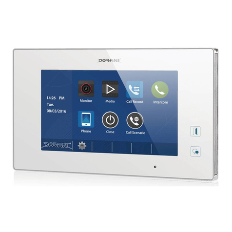
Access the General Programming section by Pressing the monitor on (anywhere on the
screen) and the Pressing the gear symbol
The menu list comes up and all settings can be changed using the onscreen adjustments.
Press on the setting that you wish to change and use the up and down buttoms to
ammend
PERATI N
Press Front doorbell button on utdoor station to create intercom call.
The screen will appear with the image of the door station pressed (on monitors
programmed to alight on call). At this time a snapshot opf the caller will be taken.
Answer by pressing NCE the Speech Symbol R Speaker Symbol – The
communication can now occur between Door and Monitor.
If a Door locking device is connected Pressing the Door release Button R Padlock 1
will trigger the lock to release.
Padlock 2 is reserved for Second locking devices connected to the same door station
– Additional Relay Module is required for this.
Ending the call is by pressing the Power ff Symbol
USING KEYPAD D R STATI N
Enter your user code followed by the # Key to trigger lock.
M NIT R
The monitor function is used to bring the Door station or Camera connected to the
system for remote viewing.

4
Pressing on the station desired will show the station on the screen, door stations can
then be activated (door locks), etc. as you would when in an intercom call.
Door stations programmed into the system will only show an image.
Cameras will only show an image if a CCTV Module is installed and Cameras connected.
Pressing the arrow symbol on top of the page enables you to access meu features for
adjusting brightness, colour and contrast.
INTERC M
Pressing Intercom will give 2 optons
Inner Broadcast – Press this button to enable instant talking to the other monitors
connected in the system.
Inner Call will ring ALL montitors connedted in the system, communication can only be
established once another monitor is answered.
Answering and Ending the call is done in the same manner as normal intercom.
PLAYBACK
Pressing Playback will enable you to access all images taken upon pressing of the
intercom door bell.
These can be deleted one by one by pressing the X button and then the Bin button.
The system holds 100 Still Images on internal storage.
The addition of a Micro SD Card in the top of the monitor (Max 32GB) will override the
orginal Still Images and will enable call recording direct to the SD Card.
The SD Card MUST be formatted for this to work. To Format the SD Card, insert the SD
card properly into the SD Card Slot, enter Main page (press monitor), Press the
Symbol, Press the “About” ption, Press the Symbol, followed by , followed by
K. This will format the card and enable image and call recording to the card.
CALL REC RD
If the Camera Symbol is pressed during a conversation, the video call will be recorded.
This can be viewed in date order with this feature.
D N T DISTURB
This enables the monitor to be put on silent mode for a designated period of time.

5
Pressing the desired time will cease all calls to this monitor.
DIVERT
If a Telephone or GSM interface has been installed, diversion can be set for the system.
Diversion can be Inactive, If No Answer or Simultaneously to the designated phone
numbers.
Pressing the phone number location will activate the keyboard, input your phone
number and press K, once completed you MUST press the save button to store all
phone numbers.
The phone numbers will ring in succession until communication is obtained, or all
numbers have been exhausted.
More details on using these modules are supplied with the supplementary modules
CL SE
Close turns of the screen and put the system into standy mode waiting a call.
PR GRAMMING C DES INT KEYPAD D R STATI NS
Program New Master Code
This is the main programming code Keep this new code in a safe place)
Step 1: Press 1234 + # Key– Door station should go white
Step 2: Enter 01 followed by # - Door Station should go Yellow
Step 3: Enter 4 digit code followed by # - Door station should go Green then White
This is now the new Installer Code
Program new User Codes 20 – 29 for Door Release 1
Step 1: Press Master Code + # Key (e.g. 1234#) – Door station should go white
Step 2: Enter User Location to Program (20 – 29) followed by # - Door Station should go
Yellow
Step 3: Enter 4 digit code followed by # - Door station should go Green then White
Repeat steps 2 & 3 to program more users – Press * to exit programming at any time
Note: If RLC adapter is installed for a seconday release of the same door station separate
users and codes need to be programmed for these.
This is done the same as above using User numbers 60 - 69

6
PR GRAMMING DATA
Keypad Data
Installer Code _____________________
Trigger 1 Trigger 2
User 20 _____________________ User 60 _____________________
User 21 _____________________ User 61 _____________________
User 22 _____________________ User 62 _____________________
User 23 _____________________ User 63 _____________________
User 24 _____________________ User 64 _____________________
User 25 _____________________ User 65 _____________________
User 26 _____________________ User 66 _____________________
User 27 _____________________ User 67 _____________________
User 28 _____________________ User 68 _____________________
User 29 _____________________ User 69 _____________________
Monitor Data
Door Station 1 Location __________________________
Door Station 2 Location __________________________
Camera 1 Location __________________________
Camera 2 Location __________________________
Camera 3 Location __________________________
Camera 4 Location __________________________
Master Monitor (8000) Location __________________________
Sub Monitor 1 (8001) Location __________________________
Sub Monitor 1 (8002) Location __________________________
Sub Monitor 1 (8003) Location __________________________

7
CONGRATULAT ONS, on your new Dorani Video ntercom Product
Dorani Video ntercoms pride themselves on providing innovative solutions in
domestic, commercial and apartment video intercom systems.
We endeavour to provide all of our clients with the highest level of customer
service, and ongoing product support.
We value your feedback, and provide you with our warranty details below.
Warranty
All Dorani Video ntercom products come with a limited 12 month warranty from
time of initial purchase.
Damage caused by incorrect installation, negligence, abuse or malicious damage
is not covered.
Damage from power strikes, surges, insect or vermin damage is not covered.

8
Other manuals for DORVT
1
Table of contents
Other DORANI Intercom System manuals