DOREGRILL MAGFLAM Series User manual

User manual for the MAGFLAM series gas rotisserie oven
2015
1
USER MANUAL
PROFESSIONAL SPIT-ROAST ROTISSERIE
OVEN
MAGFLAM + MAGFLAM SHORT GAS series models:
MAGFLAM 3
MAGFLAM 5
MAGFLAM 8

User manual for the MAGFLAM series gas rotisserie oven
2015
2
Dear customer,
You have recently purchased a DOREGRILL rotisserie oven.
Thank you for choosing our equipment. We have been working hard to perfect the reliability, convenience
and presentation of our products for over sixty years.
DOREGRILL is always at the cutting edge in our field. We pour all our skills and experience into our ovens
to ensure that we meet your expectations by striving to combine comfort and safety.
In our range, you can also find a selection of display windows and cooking modules which you can use
alongside your rotisserie oven.
In order to familiarise yourself with your new product as quickly as possible and to make the most out of it,
please read this user manual carefully. It will enable you to use every function on your oven and extend the
product’s life.
We are always seeking to meet your expectations in regard to our products. Our technical team is on hand
to guide you through installation and start-up, and reply to any questions and suggestions you may have.
Please feel free to contact us or visit our website: www.doregrill.com
DOREGRILL S.A.S.
12, rue du Moulin –B.P. 52 –Parc d’Activités du Moulin,
44880 SAUTRON
Tel: +33 (0)2 40 63 80 00 –Fax: +33 (0)2 40 63 82 67
e-mail: [email protected]
We are constantly improving our products and services. To achieve this, we reserve the right to modify any
technical, functional or visual characteristics relating to product development.

User manual for the MAGFLAM series gas rotisserie oven
2015
3
CONTENTS
2TRANSPORT AND HANDLING .................................................................................................................................8
2.1 TRANSPORT AND DELIVERY.................................................................................................................................................8
2.2 UNPACKING AND HANDLING.................................................................................................................................................8
3TECHNICAL DESCRIPTION......................................................................................................................................8
3.1 GENERAL DESCRIPTION ......................................................................................................................................................8
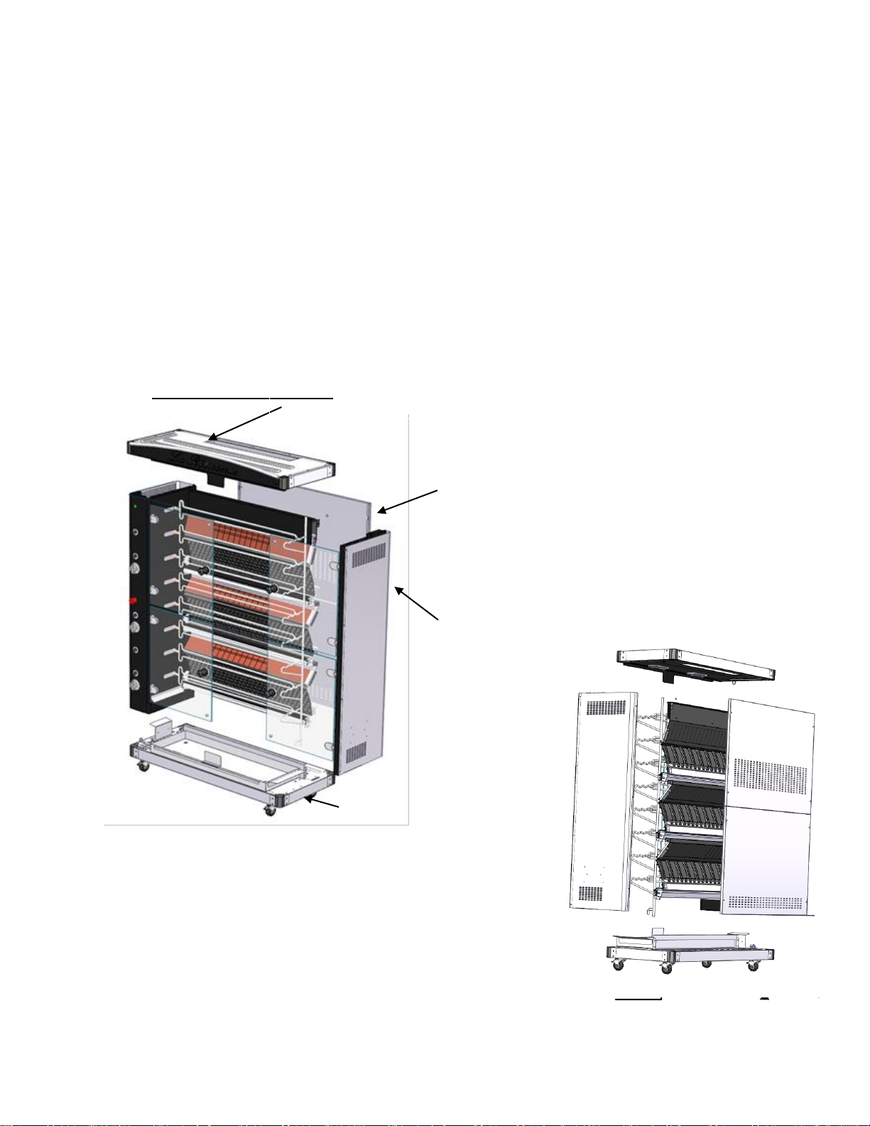
3.2 COMPONENT PARTS ...........................................................................................................................................................9
3.2.1 General exploded-view diagram ............................................................................................................9
3.3 ROTISSERIE OVEN DIMENSIONS.........................................................................................................................................16
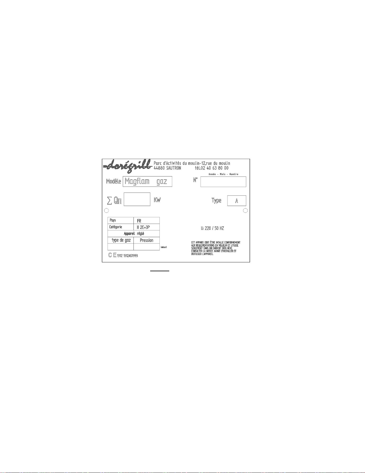
3.4 TECHNICAL DATA..............................................................................................................................................................16
3.5 INTENDED USE .................................................................................................................................................................16
3.6 ELECTRICAL PLANS ..........................................................................................................................................................16
4INSTALLATION......................................................................................................................................................16
4.1 GENERAL INSTRUCTIONS ..................................................................................................................................................16
5USE.......................................................................................................................................................................16
5.1 THE CONTROLS................................................................................................................................................................16
5.2 START-UP........................................................................................................................................................................18
6MAINTENANCE .....................................................................................................................................................19
6.1 DAILY MAINTENANCE AFTER USE .......................................................................................................................................19
6.2 WEEKLY CLEANING...........................................................................................................................................................19
6.3 END OF SEASON CLEANING (OR HALF-YEARLY)...................................................................................................................20
7TEMPERED GLASS WINDOWS –THE MAIN CAUSES OF DAMAGE .......................................................................20
7.1 THERMAL SHOCK..............................................................................................................................................................20
7.2 IMPACTS ON THE GLASS....................................................................................................................................................20
7.3 HANDLING .......................................................................................................................................................................20
8TECHNICAL CHARACTERISTICS...........................................................................................................................22
9INSTALLATION......................................................................................................................................................23
9.1 GENERAL INSTRUCTIONS ..................................................................................................................................................23
9.2 INSTALLATION ..................................................................................................................................................................24
9.3 ELECTRICAL CONNECTION ................................................................................................................................................24
9.4 STEAM VENTING...............................................................................................................................................................24
9.5 STATIC OR MOBILE CONNECTION,NATURAL GAS OR PROPANE .............................................................................................27
9.5.1 General instructions.............................................................................................................................27
9.5.2 Installation of a static rotisserie oven ..................................................................................................28
9.5.3 Installation of a mobile rotisserie oven................................................................................................29
9.5.4 Natural gas supply ...............................................................................................................................30
9.5.5 Propane supply from canisters.............................................................................................................30
10 MAINTENANCE / CUSTOMER SERVICE .............................................................................................................33
10.1 PROBLEM LOCALISATION ..................................................................................................................................................33
10.2 SPECIFIC REPAIRS............................................................................................................................................................34
10.2.1 Replacing a bulb...................................................................................................................................34
10.2.2 Opening the technical cabinet..............................................................................................................35
10.2.3 Changing the direction of a spit drive motor .......................................................................................35
10.2.4 Replacing the injector blocks...............................................................................................................35

User manual for the MAGFLAM series gas rotisserie oven
2015
4
10.2.5 POSITIONING THE MAGFLAM BURNER PROTECTOR ...............................................................................37
11 APPENDICES ....................................................................................................................................................39
11.1 ELECTRICAL PLAN FOR MAGFLAM 3 ...............................................................................................................................39
11.2 ELECTRICAL PLAN FOR MAGFLAM 5................................................................................................................................40
11.3 ELECTRICAL PLAN FOR MAGFLAM 8................................................................................................................................41
11.4 GAS CERTIFICATION ........................................................................................................................................................42
11.5 THE INFORMATION PANEL ON YOUR OVEN ..........................................................................................................................43

User manual for the MAGFLAM series gas rotisserie oven
2015
5
INFORMATION FOR THE PRODUCT USER

User manual for the MAGFLAM series gas rotisserie oven
2015
6
1. GENERAL POINTS
1.1. Labelling
This piece of equipment complies with all applicable European directives. As such, the EC logo
appears on the information panel and a compliance declaration is attached to the present
document.
-Manufacturer name and address
-EC labelling
-Equipment model (MOD)
-Electrical power (kW/A)
-Machine serial n° (MATR)
-Voltage and frequency (Volt/hertz)
-Year of manufacture
Figure 1 - (Information panel)
This panel is attached to the left hand side of the rotisserie oven, on the bottom of the technical
cabinet door.
If changing the type of gas used, the information panel which corresponds to the new configuration
will be provided with the transformation kit. You must replace the original panel with this new panel.
1.2. The importance of the manual
The present set of user instructions aims to provide users of this equipment with all the information
they need to make the most out of their rotisserie oven, extend its useable life with regular and
appropriate cleaning, solve minor problems and incidents which often do not require specialist
intervention, and avoid, by following the warnings and recommendations, any risk of injury to the
users.
The time and attention you invest in reading this manual will be amply rewarded by the information
you obtain, and by avoiding any risk of potentially irreparable damages.
This manual, valid for the MAGFLAM 3, MAGFLAM 5 and MAGFLAM 8 models, is an integral part
of our rotisserie ovens, and must remain accessible to the operators.

User manual for the MAGFLAM series gas rotisserie oven
2015
7
The manufacturer is not responsible for any damage caused to people, animals or property caused
by misuse of the equipment or non-adherence to the rules included in the manual.
IMPORTANT: This equipment is for professional use. As such, and in order to avoid
any danger, it must only be used by qualified personnel.
All components which are protected by the manufacturer or their representative
must not be handled by the installer or the user.
It must be installed in compliance with current regulations, in a well-ventilated area. The
installation, calibration and maintenance operations must be conducted by a qualified
“Gas” technician.
In the event that you wish to change the gas input, and in order to fully adhere to the
90/396/CEE European Directive concerning gas equipment, you must order the various
components required for the transformation from the DOREGRILL Company and ensure
that the transformation is completed by a qualified “Gas” technician.
1.3. Reserved rights
The reserved rights concerning this “MAGFLAM series gas rotisserie oven user manual” remain the
property of the manufacturer. No part of the manual may be reproduced or distributed without prior
written authorization by the manufacturer.
1.4. General precautions
This equipment is not suitable for use by people (including children) with reduced physical, sensory
or mental capacities, or by people with insufficient knowledge or experience unless they are
supervised or instructed in equipment safety by a person responsible for their safety.
In order to reduce the risk of serious burns, this oven MUST be placed against a wall or
against the shop façade.
The rear of the Rotisserie oven does not give any visual clues concerning its functions, or of
the potential danger relating to extreme temperatures.
If it is not possible to position the machine against a wall, the user must implement all means
necessary to protect passers-by from any contact with the Rotisserie oven (safety barrier,
wall, etc.)
1.5. Guarantee
The manufacturer guarantees that the rotisserie ovens listed have been subject to tests and trials in
our workshops.
The guarantee for these rotisserie ovens is 12 (twelve) months. Please see the Guarantee
Certificate attached to your invoice.
The use and/or replacement of components by non-original parts will void the guarantee and
release the manufacturer from all responsibility.

User manual for the MAGFLAM series gas rotisserie oven
2015
8
2TRANSPORT AND HANDLING
2.1 Transport and delivery
Our rotisserie ovens are calibrated, tested and checked in our workshops. They are carefully
packaged in order to guarantee that they arrive at their destination in the best possible conditions.
They are delivered on a pallet, strapped down and covered in film. The oven is protected by
cardboard packing, bubble-wrap, polystyrene and foam corner protection pieces. These will protect
the oven under normal transport conditions.
Once the equipment is unwrapped, ensure that it has not been damaged during transport. Any
damage must be observed and reported in the presence of the transporter. The terms listed on the
Delivery Document must be followed, within 48 hours of receiving the equipment, using a recorded-
delivery letter with proof of delivery to the transporter and the retailer must be alerted.
2.2 Unpacking and handling
When unpacking your oven, do not pierce the bubble wrap packing with an object which could
damage any of the components.
The oven can be moved around flat surfaces using its castors. If the oven must be lifted, you must
use a forklift truck with the fork passed under the base.
3TECHNICAL DESCRIPTION
3.1 General description
The MAGFLAM 3 and 6 models are mounted on a trolley or castor-mounted storage unit.
The MAGFLAM 8 rotisserie oven is mounted on a support trolley with 4 castors, 2 of which have
brakes.
It comprises:
-A structure (base, ceiling, lateral and rear cladding) in brushed stainless steel. The ceiling
and all of the internal vertical walls are made from enamelled sheet steel to facilitate cleaning.
-At the rear are burners (European standards) fitted with twin safety systems for ignition and
use, with fire-bricks around them. The burners are separated using enamelled sheet steel
deflectors which can easily be dismantled.
-Motorised Simplifil spits, each mounted directly on a motor, using an independent electrical
reducer motor fitted with a hollow, flared connector piece for easy spit insertion.
-A spit support unit located on the side opposite the motors.
-On the base, a stainless steel fat tray fitted with a drainage tap (See “User information –
Chapter 3 –Technical description” page 14, ref. 8-14)
- Two tempered steel doors on hinges, with a 120° keep-open system.

User manual for the MAGFLAM series gas rotisserie oven
2015
9
- Two Vitro-ceramic quartz lamp-projectors, protected by tempered glass screens and set into
the ceiling of the oven, providing powerful lighting.
- A control panel
- For the MAGFLAM 8, a reinforced tubular frame mounted on 4 pivoting castors –two of
which have brakes. (See “User information – Chapter 3 –Technical description” page 12, ref.
1-3)
At the back, a 20/27 or ¾ gas inlet control tap for the oven, and a 3G2.5 electric cable fitted with a
single-phase male-connector 10/16Amp cable with earth connection for the electrical connection.
3.2 Component parts
The various components of the rotisserie oven are listed in Fig. 2 below, with details further down.
3.2.1 General exploded-view diagram
A
B
C
D
FRONT VIEW
Ceiling assembly ref: A
CI spit assembly ref: B
Base assembly ref: C
Back assembly ref: D
CI motor
asembly ref:
E
REAR VIEW
E

User manual for the MAGFLAM series gas rotisserie oven
2015
10
EXPLODED VIEW OF THE MAGFLAM CEILING
Components
N°
Name
Number
N°
Name
Number
1
Top
1
9
Quartz protector glass
2
2
Rear top U
1
10
Quartz protection
2
3
80mm bracket
4
11
Wing nut
4
4
Top side U
2
12
Text window
1
5
Ceiling
1
13
Lighting system (plate on a
domino support)
1
6
Lighting system (plate on a
domino support)
1
14
Rounded front header
1
7
Quartz lamp
1
15
Rear rotisserie bar
1
8
Joint
2
16
Head guard
1
A

User manual for the MAGFLAM series gas rotisserie oven
2015
11
EXPLODED VIEW OF THE
MAGFLAM 8 CI SPIT SYSTEM
Components
N°
Name
Number
N°
Name
Number
1
Information panel
1
8
Screw-on magnet
2
2
CE spit
1
9
Klinger washer
4
3
CI U reinforcement
1
10
Strut Ø12
10
4
CI spit
1
11
Klinger washer
4
5
Hinge
4
12
Stainless steel washer
4
6
Window N°524
2
13
Fan washer
4
7
Handle system
2
14
Cap nut M6
2
B

User manual for the MAGFLAM series gas rotisserie oven
2015
12
EXPLODED VIEW OF THE MAGFLAM 8 BASE
Components
N°
Name
Number
N°
Name
Number
1
Brakeless castor
2
10
Joint
1
2
Castor with brake
2
11
Drainage tap base screw
1
3
Trolley
1
12
Drainage tap
1
4
Trolley fixing screw
4
13
Flat label safety panel
1
5
Base
1
14
Tray stop
1
6
Window N°524
2
15
Collar
1
7
Handle system
2
16
Terminal support
1
8
80 mm bracket
4
17
Bracket
9
Drainage tap base screw
1
C

User manual for the MAGFLAM series gas rotisserie oven
2015
13
EXPLODED VIEW OF THE MAGFLAM 8 CEILING
Components
N°
Name
Number
N°
Name
Number
1
Lower base
1
2
Upper base
1
D

User manual for the MAGFLAM series gas rotisserie oven
2015
14
E
EXPLODED VIEW OF THE MAGFLAM 5
CI MOTOR

User manual for the MAGFLAM series gas rotisserie oven
2015
15
Spare parts
Component names
N°
2014-model burners (17Kw fed by Flex tube
Ø12)
1
Gas safety tap for outlet pilot light Ø 12
2
Taps
3
Pilot light
4
Gas tap controllers
5
Simplifil spit
6
Windows
7
Cast iron units
8
Briquettes
9
Pilot light feed tube
10
Door handles Ø50 x 45
11
Mecagil hinges
12
Green indicator light Ø 12.7
13
Black switch 0/1
14
SPG motor + connectors + joints
15
Fan (119 x 119)
16
Motor spindles Ø10 x 300 mm
17
Cast iron tube supports Ø 21 x 1200mm
18
Indication for gas taps
19
Emergency stop button
20
Gas pressure regulator
21
Gas inlet tap
22
Indication switch 1/0
23
Gas manifold +1/4 turn valves
24
Thermocouple
25
Components

User manual for the MAGFLAM series gas rotisserie oven
2015
16
3.3 Rotisserie oven dimensions
See "User information –Chapter 8 –Technical characteristics p. 23"
3.4 Technical data
See "User information –Chapter 8 –Technical characteristics p. 23"
3.5 Intended use
Our rotisserie ovens are intended to be used to cook meat and poultry, prepared as part of the hot
food and delicatessen offerings for professionals in the food industry.
3.6 Electrical plans
See "Appendices –Chapter 11 –Electrical plans p. 36 to 38"
4INSTALLATION
4.1 General instructions
The rotisserie oven must be installed (in terms of position and connection) by authorized personnel
with the necessary technical and professional skill to install the oven according to the current
standards in the country of use.
See "User information –Chapter 9 –Installation p. 21 to 30"
5USE
5.1 The controls
Gas taps
Each of these buttons controls a burner.
First, turn off the lights.
Turn on the tap: press the tap down and turn it left to the position,
keeping it pushed down. Wait a few seconds before lighting the gas at
the pilot light, then release (safety). Next, turn it to in order to light
the burner, then choose the strength with the large or small flame.
Turn off the tap: turn the tap all the way to the right.

User manual for the MAGFLAM series gas rotisserie oven
2015
17
IMPORTANT: The gas taps have a flame adjustment system. This ranges from a large
to a small flame, with corresponding symbols on the tap handles.
Emergency stop
This must only be used in an emergency, to halt the rotisserie oven’s electrical
functions (spit rotation, lighting).
Spit motor switches
Each of these control two or three spits which each turn in alternate
directions: The spits on even-numbered levels turn in one direction, and
those on odd-numbered levels in the other. This enables large chickens to
be roasted without any risk of the rotating mechanism getting blocked.
Start-up: Press the I/0 button.
Stopping the spits: Press the I/0 button again.
Lighting switches
Uses the same type of I/0 button as above.
Switching on the lights: Press the I/0 button
Switching off the lights: Press the I/0 button again.
Installing and adjusting the spits
The spits are independent of one another, and their depth can be adjusted.
The maximum weight permitted for each motor is 20kg.
Installation: First insert the spit’s square end into the flared motor reducer
socket and, if necessary, turn is slightly to ensure that it is correctly
positioned.
Next, insert the round part, located at the other end, on the support.
Adjusting the spits on the motor side: To adjust their positions, you just
need to slide the motor reducer socket.
Adjusting the spits on the support side: The spit support has, at each
level, 3 notches. Position the round part of each spit into the desired notch.
STOP

User manual for the MAGFLAM series gas rotisserie oven
2015
18
5.2 Start-up
It is important to take certain precautions when starting up your gas rotisserie oven to ensure
optimum safety.
Important: It is formally prohibited to place trays or any other object on top of the rotisserie, or
to obstruct the exhausts or ventilation zones in any way.
Preparation
Before starting up your rotisserie oven, ensure (if it is connected to a battery of gas cylinders) that
there are sufficient cylinders to power the oven. This will vary according to the ambient temperature.
See “Installer information – Chapter 9 –Table 5 p. 29"
If your oven is mobile, do not forget to apply the front brakes once you have connected the oven to
both a single-phase electrical socket (which must have an earth plug) and a Push(1) type gas
connection gas supply.
If desired, switch on the lighting using the push button.
Fill the water tray half-way, and maintain this water level throughout the cooking time.
Lighting the burners
Slowly open the valve at the gas supply end or, if using cylinders, the gas pressure regulator on the
cylinders. Next, open the tap located behind the rotisserie oven.
IMPORTANT: Always light the burners one be one, starting by the top level and
progressively working downwards until you reach the lowest level.
If you are not using all of the spits, always start with the top ones and protect the unused
burners using their respective protectors. This will prevent fat from penetrating the
burners (which could damage them).
Only open the left-hand door. With your left hand, fully push down the desired gas tap and turn it to
the symbol (pilot) on the left, keeping it pressed down. Wait a few seconds before lighting the pilot
light with a gas lighter. Once lit, turn the tap to the larger flame to light the burner. Repeat this
process to light all of the desired levels.
1
The PUSHGAZ name is the property of GIE GAZINOX.
Cooking
We recommend piercing your chickens before roasting them in order to improve their colour and
texture.
Insert each of the prepared spits according to the method above.

User manual for the MAGFLAM series gas rotisserie oven
2015
19
See “User information – Chapter 5 –Installation and adjustment of the spits p. 18”
Adjust the depth of the spits according to the size of the birds to be roasted and the desired cooking
time. Start up the spit motor-reducers by pressing the corresponding push buttons.
IMPORTANT: Never use or insert aluminium foil into the rotisserie oven.
In order to avoid fat from spitting outwards and to ensure that the oven functions correctly, the glass
doors must remain closed during the cooking time.
Allow for 60 minutes’ cooking time for a 1.2kg chicken. However, this time may vary according to the
weather, and the quality and thickness of the item being cooked.
At the end of the cooking time, stop the motors to the desired spits and remove them, starting from
the support end and extracting the ends in the drive motors.
6MAINTENANCE
IMPORTANT:
Never use a high pressure cleaning system on the product.
Only use “Oven Special” cleaning products which are approved for use on food
equipment (1)
Never spray anything (water, detergent, etc.) on the burners.
6.1 Daily maintenance after use
While the oven is still warm, cover the burners with the protectors and give the following parts a quick
clean:
-the inner walls,
-the base,
-the ceiling,
-the glass on the windows and lights.
Once dismantled, fully clean the:
-spits and accessories,
-the fat tray (after emptying it),
-the deflectors between the burners.
1
DECAGRILL, distributed by the DOREGRILL Company, is recommended to clean your rotisserie oven
6.2 Weekly cleaning
Clean the top of the rotisserie oven.
Once dismantled, clean the removable grease filter used to trap greasy vapour from the extractor
hood using a degreasing cleaning product.
Burner protector

User manual for the MAGFLAM series gas rotisserie oven
2015
20
6.3 End of season cleaning (or half-yearly)
This cleaning procedure must be completed by an approved cleaning service provider:
-Inspection of the inside of the technical component housing,
-Wiping the motors,
-Checking the moving parts,
-Cleaning the various electrical components such as the motor-reducers, fans, indicator
lights, switches, etc.
IMPORTANT: Current legislation requires that extractor hoods and fans must be
cleaned every six months.
Dismantling the doors:
IMPORTANT:
This operation is delicate, due to the fragility of the components and the potentially hot
surfaces (heat symbol at the handle).
7TEMPERED GLASS WINDOWS –THE MAIN CAUSES OF DAMAGE
7.1 Thermal shock
There must not be a temperature difference greater than 80°C between any two points on the glass.
When this occurs, the rupture point is reached and the glass can explode at any moment.
E.g. Cleaning a hot window with a cold sponge.
7.2 Impacts on the glass
When a tempered glass window receives an impact, especially on the edge or the corner, a small
piece of glass, often the size of a pin-head, may break off.
After this, the molecular equilibrium of the glass is broken. The glass will inevitably break, whether in
the hour or within a few days.
This kind of impact may occur when unpacking the equipment, or when the user accidentally strikes
the edge of the glass with an accessory (spit, basket, fat tray, etc.) during installation.
7.3 Handling
Ill-timed and frequent movement (e.g. rolling the oven onto the pavement every day) will prematurely
weaken the glass surfaces.
IMPORTANT:
Glass, whether tempered or not, is a fragile material which must be handled with care. It
is sensitive to impact, and in no event can break by itself without one of the
aforementioned causes.
This manual suits for next models
4
Table of contents
Other DOREGRILL Kitchen Appliance manuals
Popular Kitchen Appliance manuals by other brands

Miele
Miele KWT 2671 ViS Operating and installation instructions

Gastrodomus
Gastrodomus TRH12 instruction manual

MILLU
MILLU MI-001 user guide

Garfield International
Garfield International PARAGON 103 quick guide

Tilia
Tilia FoodSaver PROFESSIONAL II user manual

Trisa electronics
Trisa electronics Star 6917 Instructions for use