Dorma RM-ED Manual

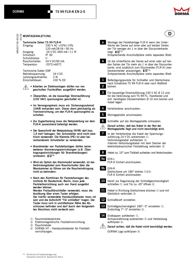
RM-ED
—
WN 059024 45532, 09/16
1
Der Rauchmelder RM-ED wird unmittelbar
(min. 10 mm)
über der Türöffnung montiert.
Der senkrechte Abstand über der
Sturzunterkante darf max. 0,1 m betragen.
Befestigungspunkte und benötigte Kabeldurch-
führungen für die Verbindung zum Drehflügelantrieb,
Deckenmelder und Handtaster anzeichnen und bohren.
Entsprechende Kabel verlegen.
Endkappen aufstecken und Rauchmeldezentrale
anschrauben.
2 Klemmenbelegung
324 V DC vom
Drehflügelantrieb
Anschluss externe
Melder mit Abschluss-
widerstand 2)
12
14
2Externe Handauslösung
mit Abschlusswiderstand 2)
10
7 NO Potentialfreier Wechsler
Kleinspannung (SELV)
24 V AC/DC, 1 A
8 NC
9 C
1Anschluss Drehflügelantrieb
ED 100, ED 250
11 Potentialfreie Klemme
16 Bus
Funktionen DIP-Schalter
1OFF = automatischer Reset
ON = manueller Reset
2OFF = 1 Stichbetrieb (Linie)
ON = 2 Stichbetrieb (Stern)
3OFF = ohne Deckenmelder
ON = mit Deckenmelder
4OFF = ohne Handtaster
ON = mit Handtaster.
Drehflügelantrieb anklemmen.
Eventuell vorhandene Deckenmelder und/oder
Handtaster anschließen – siehe Anschlusspläne.
Abschlusswiderstände beachten!
3 DIP-Schalter Reset (Wiederscharfschaltung)
Automatisches Reset
Rauchmeldezentrale stellt sich nach erfolgter Alarm-
auslösung automatisch zurück, sobald kein Rauch
bzw. Prüfgas mehr in der Rauchkammer ist. Betriebs-
anzeige leuchtet wieder grün.
Reset der Feststellanlage erfolgt über den Antrieb
(Beschreibung siehe Anleitung ED 100, ED 250).
DE
Montageanleitung
Technische Daten RM-ED
Anschlussspannung: 24 V DC −10% / +15%
Rauchschalter: 24 V DC / 50 mA
Schutzart: IP 30
Temperatur: –20°C / +40°C
Rel. Luftfeuchtigkeit: max. 93% ohne Betauung
Arbeiten an Elektroanlagen dürfen nur von geschulten
Fachkräften ausgeführt werden.
• Überprüfen, ob die bauseitige Stromzuführung
(230 VAC) zum Drehflügelantrieb spannungslos
geschaltet ist.
• Brandmelder von Feststellanlagen dürfen keine
weiteren Alarmierungseinrichtungen (z. B. Über-
tragungseinrichtungen für Brandmeldungen)
ansteuern. + 1)
• Der Rauchmelder RM-ED darf nur als Sturzmelder
eingesetzt und nur bei fester Montage an der Wand in
Betrieb genommen werden.
ÀRauchmeldezentrale
ÁRauchmelder
a Montage des Sturzmelders RM-ED, wenn die Unterfläche
der Decke auf einer oder auf beiden Seiten der Tür
weniger als 1 m über der Sturzunterkante liegt. +1)
Entsprechende Anschlusspläne siehe separates Blatt.
b Ist die Unterfläche der Decke auf einer oder auf beiden
Seiten der Tür mehr als 1 m über der Sturzunterkante,
sind zusätzlich zum Sturzmelder zwei Deckenmelder
anzubringen. +1)
Entsprechende Anschlusspläne siehe separates Blatt.
1) AAuPZF des Deutschen Instituts für Bautechnik, Berlin
2) siehe Anschlusspläne

RM-ED
—
DDORMA
4 Rote Schutzhaube von der Rauchmeldeeinheit
entfernen. Netzschalter am Drehflügelantrieb
ED 100, ED 250 auf „EIN“.
Betriebsanzeige leuchtet grün.
5 Endkappenblenden und Verkleidung aufclipsen.
6 Funktionsprüfung
Anwendungs- und Sicherheitshinweise auf dem
Prüfgas und Sicherheitsdatenblatt beachten.
Programmschalter Drehflügelantrieb auf „Dauerauf“ –
Tür öffnet sich.
Prüfgas (Hekatron 918/5) aus ca. 10 – 15 cm Entfer-
nung in Richtung Rauchkammer sprühen.
Die Betriebsanzeige schaltet auf Alarm (rot) um.
Die Feststellvorrichtung wird stromlos geschaltet und
die Tür wird geschlossen.
Betriebsanzeige leuchtet grün, sobald kein Rauch bzw.
Prüfgas mehr in der Rauchkammer ist.
Reset der Feststellanlage erfolgt über den Antrieb
(siehe Anleitung ED 100, ED 250).
7 Mitgelieferte Staubschutzhaube aufstecken, damit
während weiterer Rohbauarbeiten kein Staub in den
Rauchmelder gelangt.
Vor der endgültigen Inbetriebnahme ist die Staub-
schutzhaube zu entfernen und eine weitere Funktions-
prüfung gemäß Punkt 6 durchzuführen.
8 Funktionen der LED’s
LED an LED aus
Betriebsanzeige LED 1 (grün/rot)
Betrieb: grün
Alarm Rauchmelder: rot
Alarm Handtaster: rot
Serviceanzeige LED 2 (gelb)
Fällige Wartung: blinkt
Verschmutzung: blinkt
Störung: Dauer
Störung: blinkt
falsche Verdrahtung zum Rauchmelder /Handtaster
DIP-Schalter Änderung nach Inbetriebnahme:
LED 1: blinkt
LED 2: blinkt
Änderungen werden erst nach Betätigung des Reset-
Taster übernommen
ABNAHMEPRÜFUNG UND WARTUNG
+Merkblatt über die Verwendung von Feststellanlagen.
Wird der Sturzmelder RM-ED in Räumen mit großem
Staubanfall eingesetzt, sind die vorgeschriebenen
Wartungsintervalle unbedingt einzuhalten, oder ggf.
sogar zu verkürzen, da Staubablagerungen im Melder
zu Fehlauslösungen führen können.#
Die Rauchmeldeeinheit muss gemäß der DIN 14677
nach 8 Jahren ausgetauscht werden. Das Erreichen
der Austauschfrist wird über die Leuchtdiode LED 2
dauerhaft angezeigt.
WEITERE HINWEISE / VORSCHRIFTEN
+Zulassungsbescheid
Merkblatt über die Verwendung von Feststellanlagen.
Allgemeine Anforderungen und Prüfgrundlagen für das
Zulassungsverfahren für Feststellanlagen (AAuPZF)
des Deutschen Instituts für Bautechnik, Berlin.

RM-ED
—
DDORMA
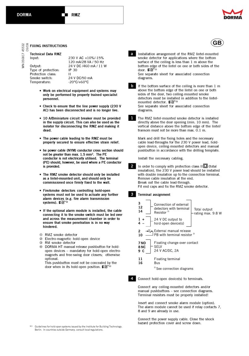
1 The RM-ED lintel-mounted smoke detector is
installed directly above the door opening (min.
10 mm). The vertical distance above the bottom
edge of the lintel/transom must not be more than max.
0.1 m.
Mark and drill the fixing holes and the necessary cable
lead-throughs for connection of swing door operator,
hold-open device, ceiling-mounted detectors and
manual pushbutton.
Install the necessary cabling.
Fit end caps and fix the RM-ED smoke detector.
2 Terminal assignment
324 V DC from
swing door operator
Connection of external
detectors with terminal
resistor 2)
12
14
2External manual release
with terminal resistor 2)
10
7 NO Connection of swing door operator
ED 200
8 NC
9 C
1Connection of swing door operator
ED 100, ED 250
11 Floating terminal
16 Bus
Functions DIP switch
1OFF = automatic reset
ON = manual reset
2OFF = 1 radial operation (line)
ON = 2 radial operation (star)
3OFF = without ceiling-mounted detector
ON = with ceiling-mounted detector
4OFF = without manual push-button
ON = with manual push-button.
Connect swing door operator.
Connect any ceiling-mounted detectors
and/or manual pushbuttons – see connection diagrams.
Terminal resistors must be properly installed!
3 Set the reset via the DIP switch.
Automatic reset (ED 100, ED 250)
The RM-ED smoke detector automatically resets
following an alarm trip and as soon as there is no
smoke or test gas in the smoke chamber. Status display
returns to green.
Reset of the hold-open system is performed by the
swing door operator (see instruction ED 100, ED 250).
EN
Fixing Instructions
Technical Data RM-ED
Input: 24 V DC −10% / +15%
Smoke switch: 24 V DC / 50 mA
Temperature: –20°C / +40°C
Rel. air humidity: max. 93% without condensation
Work on electrical equipment and systems may only be
performed by properly trained specialist personnel.
• Check to ensure that the line power supply (230 V AC)
to the swing door operator has been disconnected and
is no longer live.
• Fire/smoke detectors controlling hold-open systems
must not be used to actuate any further alarm devices
(e.g. fire alarm transmission systems). + 1)
• The RM-ED smoke detector should only be installed
as a lintel-mounted unit, and should only be
commissioned once firmly fixed to the wall.
ÀRM-ED smoke detector
ÁRM smoke detector
a Installation arrangement of the RM-ED lintel-mounted
smoke detector for applications where the bottom
surface of the ceiling is less than 1 m above the bottom
edge of the lintel on one or both sides of the door. +1)
See separate sheet for associated connection
diagrams.
b If the bottom surface of the ceiling is more than 1 m
above the bottom edge of the lintel on one or both
sides of the door, two ceiling-mounted smoke detectors
must be installed in addition to the lintel-mounted
detector. +1)
See separate sheet for associated connection
diagrams.
1) AAuPZF of the Deutsches Institut für Bautechnik, Berlin
2) See connection diagrams.

RM-ED
—
Änderungen vorbehalten
Subject to change without notice
DORMA Deutschland GmbH DORMA Platz 1 58256 ENNEPETAL Tel. +49 2333 793-0 Fax +49 2333 793-4950
www.dorma.com
4 Remove the red protective cap from the smoke detector
unit. Switch the main switch on the swing door
operator to “ON”.
ED 100, ED 250:
Status display should show green.
Reset of the hold-open system is performed by the
swing door operator (see instruction ED 100, ED 250).
ED 200:
Status display flashes green.
Press the RESET pushbutton – status display should
show green.
5 Clip on end cap trims and main cover.
6 Functional checks
Ensure compliance with instructions for use and
also the safety instructions provided on the test gas
container and safety datasheet.
Select “Permanent Open” at the program switch
of the door swing operator – the door opens.
Spray test gas (Hekatron 918/5) from a distance of
approx. 10 – 15 cm towards the smoke chamber.
After approx. 4 – 6 short bursts, the status display
should switch to alarm (red).
The hold-open device is tripped and released, and the
door closes.
ED 100, ED 250:
Status display should show green as soon as there is
no longer any smoke or test gas in the smoke chamber.
Reset of the hold-open system is performed by the
swing door operator (see instruction ED 100, ED 250).
ED 200:
Status display flashes green as soon as there is
no longer any smoke or test gas in the smoke chamber.
Press the RESET pushbutton – status display should
show green and the door opens.
7 Fit dust protection cover supplied so that dust is
prevented from entering the smoke detector during any
subsequent building or finishing work.
Prior to final commissioning, remove the dust
protection cover and perform a further function check
procedure as described in item 6.
8 Function of the LEDs
LED on LED off
Status display LED 1 (green/red)
Standby: green
Alarm smoke detector: red
Alarm manual push-button: red
Service display LED 2 (yellow)
Servicing due: flashes
Contamination: flashes
Fault: continuous
Error: flashes
incorrect wiring to the smoke detector /manual push-
button
DIP switch change after commissioning:
LED 1: flashes
LED 2: flashes
Changes will be applied only after the reset button has
been pressed.
FINAL INSPECTION AND MAINTENANCE
+See instruction sheet relating to the use and
application of hold-open systems.
If the RM-ED lintel-mounted smoke detector is used
in rooms with a high dust content, ensure compliance
with the specified maintenance intervals. These may
even have to be reduced in order to ensure that dust
deposits in the detector do not give rise to nuisance
tripping.
The smoke detector unit must be replaced after
8 years according to DIN 14677. The LED 2 will
permanently indicate when the time for replacement
has come.
FURTHER INFORMATION / REGULATIONS
+Approval certificate
Instruction sheets relating to the use and application
of hold-open systems.3)
Guidelines for hold-open systems3) published by the
Institute for Building Technology, Berlin, or equivalent
national guidelines.
3) Some documents are only printed in German as they refer exclusively to the
German market.
Table of contents
Languages:
Other Dorma Smoke Alarm manuals
Popular Smoke Alarm manuals by other brands

System Sensor
System Sensor 2151 Installation and maintenance instructions

Greenheck
Greenheck Smoke Dampers SMD-401M Specifications

Ei Electronics
Ei Electronics Ei128R Common instruction manual

Panasonic
Panasonic 4300 Specification sheet

Siemens
Siemens FCI2016-U1 Mounting & installation

Bosch
Bosch FAS-420-TM installation guide