Dorma RMZ User manual

DORMA
DORMA RMZ
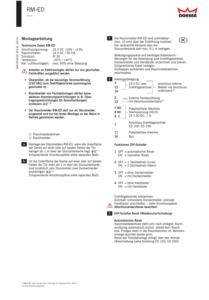
Installation arrangement of the RMZ lintel-mounted
smoke detector for applications where the bottom
surface of the ceiling is less than 1 m above the
bottom edge of the lintel on one or both sides of the
door. ☞1)1)
1)1)
1)
See separate sheet for associated connection
diagrams.
If the bottom surface of the ceiling is more than 1 m
above the bottom edge of the lintel on one or both
sides of the door, two ceiling-mounted smoke
detectors must be installed in addition to the lintel-
mounted detector. ☞1)1)
1)1)
1)
See separate sheet for associated connection
diagrams.
The RMZ lintel-mounted smoke detector is installed
directly above the door opening (min. 10 mm). The
vertical distance above the bottom edge of the lintel/
transom must not be more than max. 0.1 m.
Mark and drill the fixing holes and the necessary
cable lead-throughs for the 230 V power lead, hold-
open device, ceiling-mounted detectors and manual
pushbutton in accordance with the drilling template.
Install the necessary cabling.
In order to comply with protection class II (total
insulation), the 230 V power lead should be installed
with double insulation up to the connection terminal.
Remove cable insulation at the end.
Break out the cable lead-through.
Fit end caps and fix the RMZ smoke detector.
Terminal assignment
Connect hold-open device(s) to terminals.
Connect any ceiling-mounted detectors and/or
manual pushbuttons – see connection diagrams.
Terminal resistors must be properly installed!
Insert and connect smoke alarm module (option).
The alarm module cannot be used if relay contacts 7,
8 and 9 are already in use.
Connect the power supply cable. Close the shock
hazard protection cover and screw down.
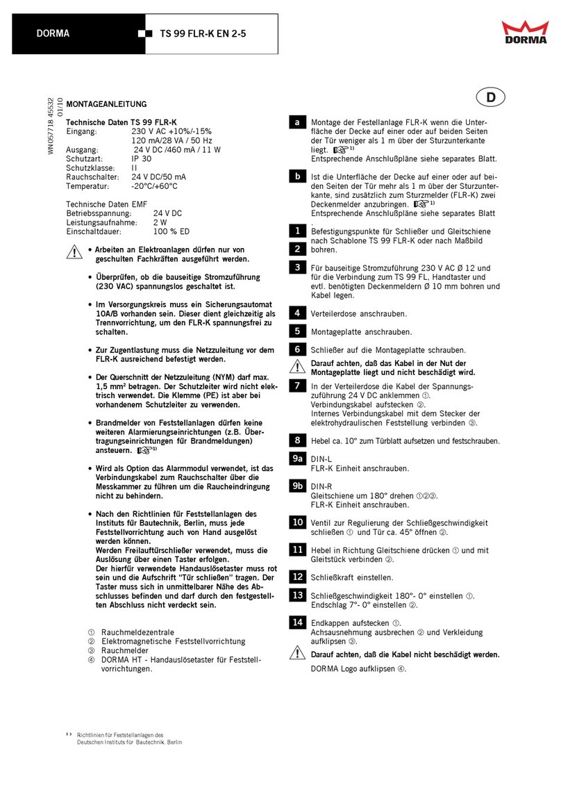
FIXING INSTRUCTIONS
Technical Data RMZ
Input: 230 V AC +10%/-15%
120 mA/28 VA / 50 Hz
Output: 24 V DC /460 mA / 11 W
Type of protection: IP 30
Protection class: II
Smoke switch: 24 V DC/50 mA
Temperature: -20°C/+60°C
• Work on electrical equipment and systems may
only be performed by properly trained specialist
personnel.
• Check to ensure that the line power supply (230 V
AC) has been disconnected and is no longer live.
• 10 A/Bminiature circuit breaker must be provided
in the supply circuit. This can also be used as the
isolator for disconnecting the RMZ and making it
dead.
• The power cable leading to the RMZ must be
properly secured to ensure effective strain relief.
• he power cable (NYM) conductor cross section should
not be greater than max. 1.5 mm2. The PE
conductor is not electrically utilised. The terminal
(PE) should, however, be used where a PE conductor
is provided.
• The RMZ smoke detector should only be installed
as a lintel-mounted unit, and should only be
commissioned once firmly fixed to the wall.
• Fire/smoke detectors controlling hold-open
systems must not be used to actuate any further
alarm devices (e.g. fire alarm transmission
systems). ☞1)
• If the optional alarm module is installed, the cable
connecting it to the smoke switch must be led over
and across the measurement chamber in order to
ensure that smoke penetration is in no way
hindered.
➀RMZ smoke detector
➁Electro-magnetic hold-open device
➂RM smoke detector
➃DORMA HT manual release pushbutton for hold-
open devices – mandatory for hold-open electro-
magnets and free-swing door closers; otherwise
optional.
This pushbutton must not be concealed by the
door when in its hold-open position. ☞1)1)
1)1)
1)
1)1)
1)1)
1) Guidelines for hold-open systems issued by the Institute for Building Technology,
Berlin. In countries outside Germany, consult local regulations.
a
b
1
2
3
4
WN 056817 45532
09/08

DORMA
DORMA RMZ
Implementing the Reset mode
Automatic reset – Jumper in position “A” (as-
delivered condition)
The RMZ smoke detector automatically resets
following an alarm trip and as soon as there is no
smoke or test gas in the smoke chamber. Status
display returns to green.
Manual reset – Jumper in position “B”
A manual reset is mandatory
- in hold-open systems with automatic swing door
operators, e.g. DORMA ED 200, CD 400 (in
accordance with DIN 18263: Part 4, item 2.5)
- in emergency exit control systems
(in accordance e.g. with IfBt Bulletin 5/983), item
3.1.4).
Status display flashes green as soon as there is no
longer any smoke or test gas in the smoke chamber.
Reset is performed by pressing the reset pushbutton.
If the manual reset mode has been implemented,
attach the enclosed RESET label to the RMZ casing.
Remove the red protective cap from the smoke
detector unit.
Switch on power supply – status display should show
green.
Clip on end cap trims and main cover.
Functional checks
Ensure compliance with instructions for use and also
the safety instructions provided on the test gas
container and safety datasheet.
Open door and engage hold-open device.
Spray test gas (Hekatron 918/5) from a distance of
approx. 10-15 cm towards the smoke chamber.
After approx. 4-6 short bursts, the status display
should switch to alarm (red). If the RMZ is equipped
with the RS alarm module (option), an audible alarm
is also sounded.
The hold-open device is tripped and released, and the
door closes.
Fit dust protection cover supplied so that dust is
prevented from entering the smoke detector during
any subsequent building or finishing work.
If the dust protection cover is fitted, the unit must be
disconnected from the power supply as the
ventilation slots of the power pack are also covered.
Prior to final commissioning, remove the dust
protection cover and perform a further function
check procedure as described in item 8.
Function of the LEDs
LED on LED off
Status display LED 1 (green/red)
Standby: green
Alarm: red
Manual reset necessary: green flashing
(see also item 5)
Service display LED 2 (yellow)
Servicing due: flashes
Contamination: flashes
Fault: continuous
FINAL INSPECTION AND MAINTENANCE
See instruction sheet relating to the use and
application of hold-open systems.
If the RMZ lintel-mounted smoke detector is used in
rooms with a high dust content, ensure compliance
with the specified maintenance intervals. These may
even have to be reduced in order to ensure that dust
deposits in the detector do not give rise to nuisance
tripping.
FURTHER INFORMATION/REGULATIONS
Approval certificate
Instruction sheets relating to the use and application
of hold-open systems.3)3)
3)3)
3)
Guidelines for hold-open systems3)3)
3)3)
3) published by the
Institute for Building Technology, Berlin, or equivalent
national guidelines.
3)3)
3)3)
3) Some documents are only printed in German as
they refer exclusively to the German market.
Subject to change without notice
☞
☞
5
6
7
8
9
10
DORMA GmbH + Co.KG DORMA Platz 1 D-58256 Ennepetal • Tel. +49 (0) 23 33 / 793-0 • www.dorma.com
Door Control Division Postfach 40 09 D-58247 Ennepetal • Fax +49 (0) 23 33 / 79 34 95
Other Dorma Smoke Alarm manuals
Popular Smoke Alarm manuals by other brands

x-sense
x-sense SD19-W user manual

FireAngel
FireAngel Thermoptek ST-622 user manual

teko
teko Astra-42A user guide

Siemens
Siemens PE-11C installation instructions

System Sensor
System Sensor DH500ACDC Installation and maintenance instructions

Resolution Products
Resolution Products RE612 CryptiX quick start guide


