Dormakaba RCI PDD-FT-1.5 User manual

PDD-FT-1.5
Fire Panel Interface
With EOL Trigger
Installation and Specifications Manual
PDD-FT-1.5
InstallatIon
ISPSFPD-1.5 PCN18003
R04-18GR-1
© 2018 dormakaba Canada Inc.
www.rutherfordcontrols.com • Phone: 1.800.265.6630 • Fax: 1.800.482.9795 • E-mail: [email protected]

Details
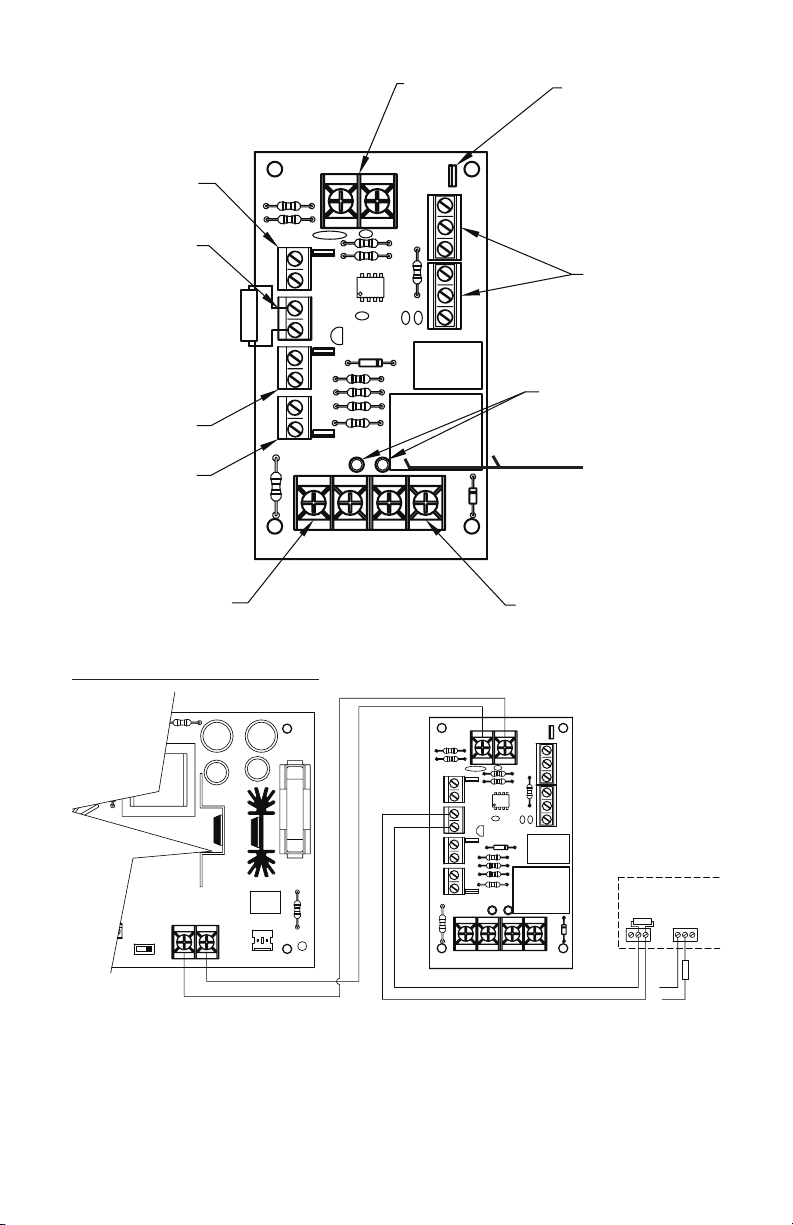
The PDD-FT board is a fire panel control interface. This board can be used to control DC
output based on a fire alarm control panel. Two outputs switch state on alarm.
Features
• NonLatchingorLatchingmode
• Universal12VDCor24VDCOperation
• Reversepolarityprotected
• NormallyON&NormallyOFFOutput
• OutputLED’sindicatecondition
• OutputscanbeTriggeredwith:
1)N/OorN/CSwitchwithSupervisedEndofLineResistor(EOL)
2)N/CSwitchwith(OVR)override
3)N/CSwitchwithAUX-INauxiliary
4)Groundonanytriggerinputwhen(GRN)Jumperisenabled
• FormCDPDTContactsIndicatesTriggerStatus
• 1.5AmpTransferRelayContacts
• Autoormanualresetbyjumperselection
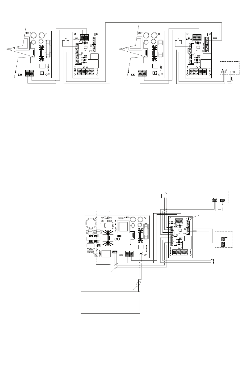
Installation Instructions
1. MountthePDD-FTboardinasuitablelocationincloseproximitytothepowersupply.
Note:
a) Groundfaultdetectionwillonlyworkifconductivestandoffsareusedandpower
supplyenclosureisproperlygrounded.
b) Asthisdevicecanbeusedtopowermultipledevicesensurethatallwiringisofan
appropriategaugeforthedevicesbeinginstalled.
c) ThisRCIboardisforuseinacontrolledenvironment.ThePDD-FT-1.5and
alldevicesconnectedtoorpoweredthroughthePDD-FT-1.5shallbeinstalledwithin
thesamecontinuousbuildingstructure.Installationmustbeinaccordancewith
localbuildingandfirecodes.CheckwithAuthorityHavingJurisdiction(AHJ)for
detailspriortoinstalling.
d) Allpowerlimitedwiringmustbeaminimumof.25”fromnon-powerlimitedwiring.
e) Maximumtorqueof7in*lbforblackinputandoutputterminals.
2.Connect“INPUT”terminalstooutputofDCsupply,payingcloseattentiontopolarityof
DCoutputfrompowersupply.
3.ConnectdevicestobepoweredtooutputterminalsofPDD-FTcontrolboard,paying
closeattentiontopolarityrequirements.Minimum22AWGandmaximumdistance
of6170ft.forfieldwiring.
4.Setjumpers(RST,OVR,AUX,andGRN)asrequiredforproperinstallation.
2

5. ConnectfirealarmcontrolpaneltoEOLinputterminals,ensurethe2.2Kresistoris
installedattheterminalsinthefirealarmpanel.Useshieldedcable.
a) Seefirealarmcontrolpanelinstallationandoperationmanualfordetailsabout
signalingrequirements.
b) Fig’s2-6inthisinstallationguidewillprovidedetailsonwiringtothefirealarm
control panel.
6. Connectanyrequiredmonitoringequipmenttothetriggerrelaysusing
appropriatecabling.Useshieldedcable.
7. TheunitistobepoweredfromthemodelRCIPowerSupplyoraULlistedpower
limitedpowersupply.
8. Applypowertopowersupplytoactivatecontrolboardandtestallconnecteddevices.
Specifications
• ForULlistedpowersupply
• UL294,6eandULCS319ClassIAccessControlSystemUnit
AccesscontrolLevels:
Endurance:Level4LineSecurity:Level1
PowerStandby:Level1DestructiveAttack:Level1
Input
• InputVoltage:12or24VDC±10%
• TypicalCurrentDrawwithnoOutputLoad:38mA@12VDC
70mA@24VDC
Output
• OutputRelayRating:6A
Monitor Inputs-UseShieldedCable
• EOL(EndofLine)Trigger:Triggerat+or–50%of2.2K
• OVRTrigger
• AUXTrigger
• ResetInput
• GroundFaultTrigger(seenote1a)
Monitor Outputs
• TriggerRelayRating:1ADPDT
Environmental
• Useinacontrolledenvironment
Warning:Improperwiringconnectionsmayresultindamagetothisproduct.
Miseengarde:Unmauvaisraccordementdescâblesrisqued’endommagerceproduit.
3

Description of PDD-FT-1.5 Connections See Fig. 1
Input Power
“-INPUT+”:2Pos.Terminalblockwithselfclampingscrewswillacceptmultiple12AWG
wiresUniversalinput.
Output Power
Two2Pos.Terminalblocks.Selfclampingscrewswillacceptmultiple12AWGwires.
“-N/ON+”arenormallyONoutputpower.ThisoutputisONwhenthePDD-FTisnottrig-
gered.“-N/OFF+”isnormallyOFF.ThisoutputisONwhenthisunitistriggered.Thetrans-
ferrelayisratedat1.5Amps.
Power LED’s
Aredledaboveeachoutputindicateswhichoutputisactive.
Input Trigger EOL*
2Pos.Terminalblock–Willaccept12AWGwire.Thisinputmustseethe2.2Kohmendof
lineresistortobeinthenormalsetcondition.Achangeinresistanceof±50%willcause
thetriggerrelaystodropoutintheTriggeredmode.Thischangeinresistanceiscaused
bythesupervisedwirebetweentheEOLatthefirepanelandthePDD-FTbeingshortedor
opened.TheEOLsupervisesthepairofwires.
Input Trigger OVR*
2Pos.Terminalblock-Willaccept12AWGwire.Thispairisnormallyclosedandcanbe
connectedtoanoverrideswitch.WhenOVRisopen,unitwilltrigger.
Input Trigger AUX-IN*
2Pos.Terminalblock-Willaccept12AWGwire.Thispairisnormallyclosedandcanbe
connectedtoanauxiliarydevice.WhenAUX-INisopen,unitwilltrigger.
Reset 2 Pos. Terminal Block*
2Pos.Terminalblock-Willaccept12AWGwire.Whenthispairisshorted,inputtriggers
donotlatch.Ifpairisopen,theinputtriggerswilllatchuntilalarmiscorrectedandRESET
ismomentaryclosedtoresettrigger.
*Minimum22AWGandmaximumdistanceof6170ftforfieldwiring.
Jumpers RST - OVR - AUX
Jumpersareusedtoactivate(remote)featuresasrequired.
Jumpers GRN
Thisjumperisusedtoenablegroundsupervisionortheinputs.Ifthejumperisconnected
tobothheaders,andthemountingholeadjacenttojumperisconnectedtoearthground,a
groundonanyoftheinputtriggerswillcauseatrigger.
Trigger Status Terminal block
Two3Pos.Terminalblocks-Willaccept12AWGwire.FormCDPDTContactwitha1
Ampratingwillindicatetheconditionoftrigger.CandNOarenormallyopeninthenormal
energizenottriggeredstate.CandNCarenormallyclosedinthenormalenergizednottrig-
geredstate.ThesecontactsmaybeusedtoprovidefeedbacktotheFACPorotherauxilary
devices.
4

Fig.2-FirePanelConnectionsforNon-Latching
AutomaticResetOperation
ThisapplicationillustrateshowtoconnectthePDD-FTtoapowersupplyformaininput
aswellasafirealarmcontrolpanel.Ifwiredinthismanner,outputswillchangestateonly
aslongasthefirealarmrelayisactive.WhenthefirealarmresetsthePDD-FToutputswill
also reset.
- N/OFF +- N/ON +
- INPUT +
GRN
EOL
RESET
AUX
OVR
RST
AUX - IN
OVR
CNO NC
TRIGGERED
2.2 K
PDD-FT
CNO NC
TRIGGERED
DC Input
Trigger Output
Ground Fault Jumper
Reset Input
End Of Line
Override Input
Auxilary Input
Normally "On" Output Normally "Off" Output
Output Led's
-BAT+
- Output +24V 12V DC - N/OFF +- N/ON +
- INPUT +
GRN
EOL
RESET
AUX
OVR
RST
AUX - IN
OVR
CNO NC
TRIGGERED
PDD-FT
CNO NC
TRIGGERED
OUTPUT
NC
FIRE PANEL
BY OTHERS
NO
CNC NO
2.2 K
OUTPUT
2.2 K
NC
C NO
5
Fig.1-PDD-FT-1.5Connections
Application Diagrams

Fig.3-FirePanelConnectionsforLatchingReleasewithN/OManual
Reset
ThisapplicationillustrateshowtoconnectthePDD-FTtoapowersupplyformaininputas
wellasafirealarmcontrolpanel.Ifwiredinthismanner,outputswillchangestatewhen-
everthefirealarmrelayactivatesandremainlatchedinthetriggeredstateuntilresetby
activatingtheN/Oswitch.
Note:RemoveRSTjumperformanualresetoperation.
Remarque:RetirezlabretelleRSTpoureffectueruneréinitialisation manuelle.
Fig.4-ConnectionsforNon-Latchingreleaseresetusingmultiple
PDD-FT boards
ThisapplicationillustrateshowtoconnectthePDD-FTtoapowersupplyformaininput
aswellasafirealarmcontrolpanel.Ifwiredinthismanner,outputswillchangestateonly
aslongasthefirealarmrelayisactive.WhenthefirealarmresetsthePDD-FToutputswill
alsoreset.ConnectingtheEOLinputofoneboardtothetriggerrelayofthenextboardas
shownwillallowforoverrideandresetofmultipleboards.
Note:TheRSTjumpermustbeleftinplaceonallboardsforautomaticresetoperation.
Remarque:LabretelleRSTdoitêtre laisséeenplacesurtouslespanneauxpoureffectuer
une réinitialisationautomatique.
-BAT+
- Output +24V 12V DC - N/OFF +- N/ON +
- INPUT +
GRN
EOL
RESET
AUX
OVR
RST
AUX - IN
OVR
CNO NC
TRIGGERED
PDD-FT
CNO NC
TRIGGERED
OUTPUT
NC
FIRE PANEL
BY OTHERS
NO
CNC NO
2.2 K
OUTPUT
2.2 K
NC
C NO
-BAT+
- Output +24V 12V DC - N/OFF +- N/ON +
- INPUT +
GRN
EOL
RESET
AUX
OVR
RST
AUX - IN
OVR
CNO NC
TRIGGERED
PDD-FT
CNO NC
TRIGGERED
OUTPUT
NC
FIRE PANEL
BY OTHERS
NO
CNC NO
2.2 K
OUTPUT
2.2 K
NC
C NO
-BAT+
- Output +24V 12V DC - N/OFF +- N/ON +
- INPUT +
GRN
EOL
RESET
AUX
OVR
RST
AUX - IN
OVR
CNO NC
TRIGGERED
PDD-FT
CNO NC
TRIGGERED
2.2 K
6

Fig.5-ConnectionsforlatchingreleasewithN/Omanualresetusing
multiplePDD-FTboards(Master&Slave)
ThisapplicationillustrateshowtoconnectthePDD-FTtoapowersupplyformaininput
aswellasafirealarmcontrolpanel.Ifwiredinthismanner,outputswillchangestate
wheneverthefirealarmrelayactivatesandremainlatchedinthetriggeredstateuntil
MasterisresetbyactivatingtheN/Oswitch.ConnectingtheEOLinputofoneboardtothe
triggerrelayofthenextboardasshownwillallowforresetofmultipleboards.
Note: TheRSTjumpermustbeleftinplaceonallboardsslaveexcepttheonethatis
directlyconnectedtothefirealarm(Master),alongwithreset,andoverrideswitches.
Remarque: LabretelleRSTdoitêtre laisséeenplacesurtouslespanneauxasservis,sauf
celuiquiestdirectementconnecté àl’alarmedefeu(d’exploitation),situé près des boutons
de réinitialisationetd’annulation.
Fig.6-Fire Panel
Connectionsfor
LatchingTriggerwith
N/OManualReset
andN/Coverridew
BatteryBackup
This application
illustrates how to
connect the PDD-FT to
anRCIPowerSupplyfor
maininput,ACfailure
as well as a fire alarm
controlpanel.Ifwired
inthismanner,trigger
outputswillchangestate
wheneverthefirealarm,
orACfailurerelaysactivate.ThePDD-FToutputswillremaininthetriggeredstateuntil
bothrelayshavebeenresetandtheN/Omanualresetistriggered.
Note: EnsurejumpersforRST,OVR,andAUXINareremovedtoallowterminalstooperate
correctly.
Remarque:Assurez-vousquelesbretellesRST,OVRetAUXINsontretirées afin de
permettreauxterminauxdefonctionnercorrectement.
-BAT+
- Output +24V 12V DC - N/OFF +- N/ON +
- INPUT +
GRN
EOL
RESET
AUX
OVR
RST
AUX - IN
OVR
CNO NC
TRIGGERED
PDD-FT
CNO NC
TRIGGERED
OUTPUT
NC
FIRE PANEL
BY OTHERS
NO
CNC NO
2.2 K
OUTPUT
2.2 K
NC
C NO
-BAT+
- Output +24V 12V DC - N/OFF +- N/ON +
- INPUT +
GRN
EOL
RESET
AUX
OVR
RST
AUX - IN
OVR
CNO NC
TRIGGERED
PDD-FT
CNO NC
TRIGGERED
2.2 K
LN-BAT+
G
- Output +
GRN
24V 12V
NO C NC
AC Fail DC
AC
- N/OFF +- N/ON +
- INPUT +
GRN
EOL
RESET
AUX
OVR
RST
AUX - IN
OVR
CNO NC
TRIGGERED
PDD-FT
CNO NC
TRIGGERED
OUTPUT
NC
FIRE PANEL
BY OTHERS
NO
CNC NO
2.2 K
OUTPUT
2.2 K
NC
C NO
2.2 K
POWER SUPPLY
INTER-CONNECT.
N/O MANUAL RESET
SEE NOTE 4.
EOL
RESET
RST
BATTERY
-BAT+
N/C MANUAL OVER-RIDE
SEE NOTE 3.
AC FAIL CIRCUIT
ONLY REQUIRED WITH
BATTERY BACKUP.
SEE NOTE 5.
Non-power limited
Power limited
Power limited
3) FOR MANUAL OVER-RIDE REMOVE JUMPER "OVR"
4) FOR MANUAL RESET REMOVE JUMPER "RST"
5) FOR AUX-IN REMOVE JUMPER "AUX"
6) JUMPER GRN IS FOR GROUND FAULT DETECTION
ON ENABLES GROUND FAULT, REMOVED DISABLES
GROUND FAULT.
AND INSTALL N/C SWITCH.
AND INSTALL A N/O SWITCH.
AND INSTALL A N/C CIRCUIT.
1) DISCONNECT AC INPUT PRIOR TO SERVICING.
SPACING OF .25" FROM NON-POWER LIMITED CIRCUITS.
2) ALL POWER LIMITED CIRCUITS TO HAVE A MINIMUM
NOTES 3-6 REFER TO PDD-FT ONLY
NOTE:
GROUND FAULT JUMPER
SEE NOTE 6.
7

Notes
___________________________________________
___________________________________________
___________________________________________
___________________________________________
___________________________________________
___________________________________________
For Technical Support:
1-800-265-6630or519-621-7651|www.rutherfordcontrols.com
PDD-FT-1.5TroubleshootingGuide
Problem Solution
-CheckACPower.
-CheckPowerSupplyforvoltageoutput.
-Checkdevicesconnectedtooutputsfor
ashortcircuit.(PTC’smayrequireshort
toberemovedforseveralminutes
beforeautomaticallyresetting).
-Checktriggerjumpers.OutputLED
shouldbelitifoutputisactive.
-Checkforproperwiringconnectionson
triggerconnections.
-Ensurethat2.2Kresistorisinstalledat
EndofLinepositioninthewiring.
-Checkdevicesconnectedtooutputsfor
ashortcircuit.(PTC’smayrequire
shorttoberemovedforseveralminutes
beforeautomaticallyresetting.)
NoDCoutputfromterminals.
Triggerisactiveandwillnotreset.
Troubleoutputrelayisde-energized.
(Relayterminalsarelabeledshownin
theNormal,energized,“notrouble”
condition.Relaysareenergizedwhen
notroubleisdetected.)
Table of contents
Popular Control Panel manuals by other brands

Linear
Linear Security DUAL 824 Installation & programming instructions

Panasonic
Panasonic AWRP501 - HYBRID CONTROL PANEL operating instructions

Honeywell
Honeywell Fire-Lite Alarms ES-200X manual

Velux
Velux KLR 200 quick guide

FRIMEC
FRIMEC CBE24 Technical manual

Citron
Citron ZigBee SC-TZ1-02 instruction manual

Smarteh
Smarteh LPC-2.DT1B user manual

Crowcon
Crowcon Crowcon Gasmaster Installation, operation and maintenance

Digital Equipment
Digital Equipment Pro-face FP-3710K Series installation guide

Visonic
Visonic POWERART installation instructions

Siemens
Siemens LED-3 installation instructions

Valley
Valley ClassicPlus owner's manual