Dormakaba SafeRoute User guide

EN
WN 059722 45532 – 2019-03
System manual
SafeRoute®-System
Mini, Basic und Standard
Contents
1 About this document 2
1.1 Contents and purpose 2
1.2 Target group 2
1.3 Other applicable documents: 2
1.4 Documents storage 2
1.5 Abbreviations 2
1.6 Symbols used 2
1.6.1 Hazard categories 2
1.6.2 More symbols 2
2 Safety 3
2.1 Intended use 3
2.2 General safety instructions 3
2.3 Personnel qualification 3
3 Product description 3
3.1 Parts included 3
3.2 Technical information 3
3.3 Basic components 3
3.3.1 SafeRoute® Control Unit 3
3.3.2 Emergency button with connected key
switch 3
3.3.3 Electrical door lock STV xxx 3
3.3.4 Power supply unit 4
3.3.5 DCW® bus 4
3.4 Extension of the SafeRoute® system 4
3.4.1 Additional DCW® components 4
3.4.2 Inputs and outputs on the SCU 4
3.4.3 RS232 interface at the SCU (available
from Basic license) 4
3.5 Functional scope 4
3.5.1 Release and unlock 4
3.5.2 Relocking 4
3.5.3 Monitoring 4
3.5.4 Visual and audible indicator 4
4 Mounting 5
4.1 Requirements for mounting a SafeRoute®
system 5
4.1.1 Door unit 5
4.1.2 Requirements for fire and smoke
protection doors 5
4.2 Mounting the components 5
4.2.1 DCW® bus addressing (door entry
system) 5
5 Commissioning 5
5.1 Put the SafeRoute® system into operation 5
5.1.1 SCU-UP and SCU-TL as SafeRoute®
Control Unit 5
5.1.1.1 Configure an SCU-UP/SCU-TL 5
5.1.2 SCU-DR as SafeRoute® Control Unit
(from Basic license) 6
5.1.2.1 Configure an SCU-DR 6
5.2 Parameterization with TMS Soft® (from Basic
license) 6
5.3 Handover of the documentation to the facility
operator 6
6 Status query of a configured unit 7
6.1 Querying the status of an SCU-UP/SCU-TL 7
6.2 Querying the status of an SCU-DR 7
7 Troubleshooting 8
7.1 Illuminated ring display in case of alarm and
malfunction 8
8 Replacement and removal of components 11
8.1 Replace non-safety related DCW® components 11
8.2 Remove non-safety related DCW® components
completely 11
8.3 Replace/remove safety-related DCW®
components 11
8.4 Update internal DCW® table 11
8.4 Reset configuration to factory settings 11
9 Maintenance 12
10 Disassembly, recycling and disposal 12
11 Manufacturer's declarations and test
certificates 12
12 Annex 13

2SafeRoute® System 2019-03
WN 059722 45532
dormakaba About this documentSystem manual
1 About this document
1.1 Contents and purpose
This document contains the information and
instructions for the installation and operation of
a SafeRoute® system on an emergency exit door
unit according to EltVTR (12/1997 version) and DIN
EN13637:2015. The functional scope information
refers to a SafeRoute® system with the Standard
license.
1.2 Target group
This document is intended for assembling technicians
and specialists authorized by dormakaba for the
installation, operation, maintenance and testing of a
SafeRoute® system.
1.3 Other applicable documents:
The following documents belong to the unit’s
complete documentation and must be observed:
• The installed individual components’ assembly
instructions and documents
• The operation manual
• The inspection log for the door unit on which the
SafeRoute® system was installed
• The TMS Soft® handbook
• The approved components’ declaration of
conformity
1.4 Documents storage
This document and the other applicable documents
must be handed over to the facility operator after
commissioning. The facility operator must keep
the documents for the entire service life and make
them accessible to the persons responsible for the
inspection and maintenance of the emergency exit
door unit.
1.5 Abbreviations
Abbreviation Definition
SCU-xx
SafeRoute® Control Unit - Control
unit of a SafeRoute® system in three
versions:
• SCU-UP = Flush mounting
• SCU-TL = in the door terminal
STL-G
• SCU-DR = DIN rail mounting
SLI License card
SLI-A Application
STL-G Door terminal with emergency
button SCU-TL and key switch ST
STV xxx Electrical door lock
ST Key switch
1.6 Symbols used
1.6.1 Hazard categories
WARNING
This signal word indicates a situation of
potential risk, which could lead to death or
serious injury if not averted.
1.6.2 More symbols
TIPS AND RECOMMENDATIONS
This signal word indicates useful information
for efficient and trouble-free operation.

3SafeRoute® System 2019-03WN 059722 45532
dormakaba System manual Safety
2 Safety
The following instructions must be observed by the
installer and facility operator. The installation of
escape route security systems must not impede the
unhindered escape of persons in the event of danger.
Only use dormakaba spare parts or spare parts
approved by dormakaba.
2.1 Intended use
The escape route security system SafeRoute® is an
electrical locking system on doors in emergency and
escape routes, which counteracts any misuse of the
escape route. When using the dormakaba escape
route security system SafeRoute®, the technical data
and environmental conditions of the components
used must be taken into account. Only components
and parts approved by dormakaba for a SafeRoute®
system may be used (see current list www.
dormakaba.com).
The intended use also includes compliance with
all information in this document and in the other
applicable documents (see also Ch. 1.3).
2.2 General safety instructions
WARNING
Danger to life due to blocked escape routes
Mounted devices and components as
well as their settings can prevent people
from escaping in an emergency if they are
handled improperly.
2.3 Personnel qualification
Mounting, commissioning, testing and maintenance
of the SafeRoute® system may only be performed by
persons authorized by dormakaba.
3 Product description
A SafeRoute® system is an electrical locking system
for emergency exit doors. The SLI license card
defines the SafeRoute® system’s functional scope. A
SafeRoute® system consists of various components
depending on the requirements.
3.1 Parts included
• Mini, Basic or Standard license card
• Battery (for the clock function from license
standard)
• System manual
• Operation manual
• Inspection logbook
3.2 Technical information
• Systems according to EltVTR must be operated
with 24 V ± 10% (to maintain the retention force for
locking devices).
• Systems outside the scope of the EltVTR can be
operated functionally safe with 24 V ± 15%.
3.3 Basic components
6
5
4
1
2
3
Fig. 1 Example execution of a SafeRoute® system
A SafeRoute® system consists of at least the
following basic components:
1an emergency button
2a key switch ST connected to SCU
3a SafeRoute® Control Unit SCU
4an SLI license card
5an electrical door lock STV xxx
6a power supply, e.g. power supply unit NT-S24-1.5
The basic components are connected via a four-core
control cable (DCW® bus).
The connection of additional components is possible.
3.3.1 SafeRoute® Control Unit
The SCU with the inserted license card is the
SafeRoute® system’s control unit. The license card
defines the SafeRoute® system’s functional scope. The
SCU is available in three versions:
• SCU-UP: consists of an SCU with emergency button
for flush mounting
• SCU-TL: consists of an SCU with emergency button
in the door terminal STL-G
• SCU-DR: consists of an SCU for DIN rail mounting
(SCU-DR can be used from the Basic license.)
3.3.2 Emergency button with connected
key switch
The emergency button releases the electric locking
device when pushed. The emergency button’s multi-
colored illuminated ring provides information about
the current door status. A key switch (ST) must be
connected to the emergency button.
The key switch offers the following functions:
• Locking and unlocking
• Alarm acknowledgement

4SafeRoute® System 2019-03
WN 059722 45532
dormakaba Product descriptionSystem manual
3.3.3 Electrical door lock STV xxx
The electric door lock locks the door and releases
the door on request. Up to four different as well as
identical door locks can be connected to a SafeRoute®
system via the DCW® bus. All dormakaba STV xxx
door locks are permitted. Door locks without DCW®
bus are integrated via the STV-A adapter.
3.3.4 Power supply unit
The power supply unit feeds the 24V DC voltage for
all SafeRoute® and DCW® components at any point
in the DCW® bus. If there is an increased demand for
power, several power supply units can be connected
(the +24V line between the power supplies must
then be disconnected). Any power supply units used
must meet the dormakaba requirements (definition
of power supplies: see Declaration of Conformity at
www.dormakaba.com).
3.3.5 DCW® bus
The DCW® bus connects the components. Power is
supplied via the DCW® bus (four-core control cable).
dormakaba recommends the following type of lead:
• For bus routes up to max. 300 m: J-Y(St)Y 2x2x0.8
3.4 Extension of the SafeRoute® system
3.4.1 Additional DCW® components
Depending on requirements, the SafeRoute®
system can be supplemented with additional DCW®
components, e.g. additional emergency button, key
switches, self-locking panic locks, etc.
List of all approved components:
The list of approved components and parts and the
declaration of conformity are available at www.
dormakaba.com.
3.4.2 Inputs and outputs on the SCU
Each SCU has inputs and outputs where alarm and
signaling systems, external access control systems
and other components can be connected or switched.
The input and output functions can be parameterized
with TMS Soft® from the Basic license.
3.4.3 RS232 interface at the SCU
(available from Basic license)
The SCU with the inserted license card can be
connected to TMS Soft® (PC computer) via the RS232
interface. The connection can also be made via an
LON or LAN network adapter.
3.5 Functional scope
The functions of a SafeRoute® system result from
the connected components and the license card
(see Chap. 12). The preconfigured functions (default
values) can be changed with TMS Soft® and the
SafeRoute® configuration software (possible from
Basic license).
The SafeRoute® system’s functional scope can be
expanded by additional components and SLI-A
application cards (from Basic license).
3.5.1 Release and unlock
The following functions are available (default values):
• Release via emergency button (with alarm trigger)
• Release in case of power failure
• Temporary unlocking
• Long-term unlocking (from Standard license)
• Permanent unlocking
• Release by an alarm system (fire, danger, smoke
detectors, sprinklers, etc.)
3.5.2 Relocking
The following functions are available (default values):
• Automatically after power failure
• Temporary unlocking: Automatically after expiry of
the set relocking time
• Long-term unlocking: Automatically after expiry of
the set relocking time
• Permanent unlocking: Automatically after closing
the door and operation via key switch
3.5.3 Monitoring
The default values are:
• Tamper monitoring
• “Door open” monitoring with two different time
ranges for pre- and main alarm (from Standard
license)
3.5.4 Visual and audible indicator
The following displays are possible:
• Operating of the emergency button
• Alarm trigger
• Activation of locking and unlocking
• Relocking failed
• Pending maintenance
• Malfunction and error reports
• Connected components

5SafeRoute® System 2019-03WN 059722 45532
dormakaba System manual Mounting
4 Mounting
4.1 Requirements for mounting a
SafeRoute® system
4.1.1 Door unit
All door unit components must be approved by the
manufacturers for use as part of an emergency exit
unit and must function properly.
4.1.2 Requirements for fire and smoke
protection doors
When mounting a SafeRoute® System in preventive
fire protection, the fire and smoke protection doors’
properties must not be impaired.
Mounting is only permitted if the proof of usability
for the fire and smoke protection door allows for
mounting and the proof of usability’s stipulations are
observed.
Further information can be found in the report
“Permissible changes and additions to fire protection
closures” from the Deutsches Institut für Bautechnik
(DIBt 1/1996), Berlin.
4.2 Mounting the components
The SLI license card and the battery (from Standard
license) are plugged into the SafeRoute® Control Unit.
The further mounting and connection of the
SafeRoute® system’s individual components is carried
out according to the unit configuration and the
assembly instructions. All connected components of
the SafeRoute® system are entered in the respective
door unit’s inspection log.
4.2.1 DCW® bus addressing (door entry
system)
Each DCW® component has a DCW® bus address.
Similar DCW® components must have different
DCW® bus addresses. The setting is made via the
DCW® DIP switches on the components.
5 Commissioning
5.1 Put the SafeRoute® system into
operation
Depending on the SafeRoute® Control Unit used
(SCU-UP, SCU-TL or SCU-DR from Basic license), the
procedure and status displays differ.
5.1.1 SCU-UP and SCU-TL as SafeRoute®
Control Unit
The status display is indicated by the illuminated ring.
The LED segments are assigned to the DCW® security
components and light up or flash depending on the
status of the connected DCW® component.
STV 1 (Adr. 1)SCU 1 (Adr. 1)
STV 2
(Adr. 2)
SCU 2
(Adr. 2)
STV 3
(Adr. 3)
SCU 3
(Adr. 3)
STV 4 (Adr.4)SCU 4 (Adr. 4)
Fig. 2 Assignment of the LED segments in the illuminated
ring
5.1.1.1 Configure an SCU-UP/SCU-TL
1. Connect the power supply.
‣ The illuminated ring on the SCU’s emergency
button flashes briefly (for initialization views
see chapter 6.1) and changes to the rainbow
view.
2. Press the S4 service button on the SCU and keep
it pressed for 12 s.
‣ After 8 s, a signal sounds.
‣ After 12 s, another signal sounds and the
illuminated ring lights up blue.
‣ The connected components are detected and
displayed on the illuminated ring (flashing
green/blue alternately).
3. Check if the connected components are displayed
with the correct address.
TIPPS UND EMPFEHLUNGEN
Duplicated DCW® addresses are indicated
with yellow flashing.
4. Press and hold the service button for 3 s.
‣ The illuminated ring changes to the operation
indicator.
→The SCU-UP/SCU-TL is configured.

6SafeRoute® System 2019-03
WN 059722 45532
dormakaba CommissioningSystem manual
If the illuminated ring does not change to the
operation indicator (permanently lit red):
1. Use the key switch to push right to left.
‣ The illuminated ring on the emergency button
lights up red permanently.
‣ The STVxxx locks.
→The SCU-UP/SCU-TL is configured.
If the alarm signal "The emergency button is pressed"
is pending (see Chap. 7 on page 8), reset the
alarm signal:
1. Turn and hold the key to the right on the key
switch.
2. Press the emergency button for 1s and then
release.
3. Push the key over the middle to the left and bring
it back to the middle position.
4. Remove the key.
‣ The electric locking device is active.
→The SCU-UP/SCU-TL is configured.
5.1.2 SCU-DR as SafeRoute® Control Unit
(from Basic license)
The status display during the configuration takes
place via LEDs on the board. The LEDs light up or
flash depending on the status of the connected
DCW® component.
In 1In2 In 3In4
BTRDCW
CPU2
CPU1
SLI
Out2Out1 Out3 Out4
Fig. 3 Arrangement of the LEDs on the SCU-DR board
5.1.2.1 Configure an SCU-DR
1. Connect the power supply.
‣ The DCW® LED lights up red when correctly
connected.
‣ The SLI LED lights up yellow when the license
is inserted.
‣ The LEDs from In 1 to In 4 change to the
initialization view and display the license.
In 1 - 4 off no/defective license card
In 4 on SLI Basic
In 3 on SLI Standard
‣ The illuminated ring on the emergency button
flashes briefly and changes to the rainbow
view.
2. Press and hold the S4 service button on the SCU-
DR for 12s.
‣ After 12 s, the illuminated ring on the
emergency button lights up blue.
‣ The BTR LED flashes green.
‣ The connected components are detected and
displayed on the illuminated ring (flashing
green/blue alternately).
3. Press and hold the S4 service button for 3s.
‣ The BTR LED lights up green.
‣ The DCW® LED lights up red.
‣ The CPU1 and CPU2 LEDs light up red (CPU1)
and yellow (CPU2).
‣ The illuminated ring on the emergency button
lights up red permanently.
4. Use the key switch to push right to left.
‣ The illuminated ring on the emergency button
lights up red permanently.
‣ The STVxxx locks.
→The SCU-DR is configured.
5.2 Parameterization with TMS Soft®
(from Basic license)
With TMS Soft® and the SafeRoute® configuration
software, the functions of the components and
the SafeRoute® system can be adapted. For more
information, see the TMS Soft® handbook.
The settings made with the SafeRoute® configuration
software must be entered in the respective door unit’s
inspection log.
5.3 Handover of the documentation to the
facility operator
All documents relevant for proper operation are
handed over to the facility operator after initial
commissioning:
• The installed individual components’ assembly
instructions and documents
• The operation manual
• The door unit’s inspection log
• This system manual
7SafeRoute® System 2019-03WN 059722 45532
dormakaba System manual Status query of a configured unit
6 Status query of a configured
unit
After a power failure, the license used and the status
of all connected components are displayed in several
initialization steps on the SafeRoute® Control Unit
emergency button’s illuminated ring.
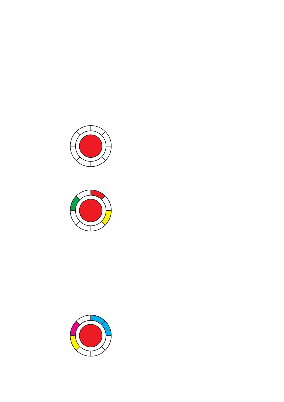
6.1 Querying the status of an SCU-UP/
SCU-TL
1. Disconnect the power supply.
2. Reconnect the power supply.
‣ The illuminated ring on the emergency button
changes to Initialization view 1:
White (lit up) = SLI license card
SLI Premium
without SLI
SLI Mini
SLI Basic
SLI Standard
‣ The illuminated ring changes to Initialization
view 2:
STV 1
SCU 1
STV 2
SCU 2
STV 3
SCU 3
STV 4
SCU 4
Red = STV-xxx available.
The display flashes red (2.5 Hz) if there is no
configuration and the STV is not assigned to
any SCU.
Green = SCU emergency button available.
The indicator flashes green (2.5 Hz) if the
emergency button is not yet configured.
Yellow = Malfunction: STV/SCU is missing/
defective.
‣ The illuminated ring changes to Initialization
view 3:
ST DCW® 1
I/O DCW® 1
ST DCW® 2
I/O DCW® 2
ST DCW® 3
I/O DCW® 3
ST DCW® 4
I/O DCW® 4
Blue = ST DCW® address X available.
Magenta = I/O DCW® available.
Yellow = Malfunction: STV/SCU is missing/
defective.
‣ The SCU switches to the operating state and
the illuminated ring lights up red permanently.
→The door is locked.
6.2 Querying the status of an SCU-DR
1. Disconnect the power supply.
2. Reconnect the power supply.
‣ The LEDs from In 1 to In 4 change to the
initialization view and display the license.
In 1 - 4 off no/defective license card
In 4 on SLI Basic
In 3 on SLI Standard
‣ The illuminated ring lights up/flashes green/
yellow briefly.
‣ The LED segment 1 on the SCU emergency
button’s illuminated ring lights up white.
‣ The illuminated ring on the emergency button
lights up red.
→The door is locked.
8SafeRoute® System 2019-03
WN 059722 45532
dormakaba TroubleshootingSystem manual
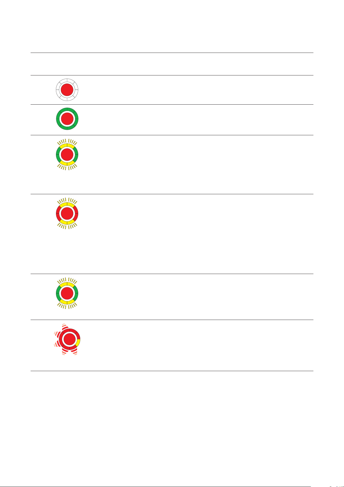
7 Troubleshooting
7.1 Illuminated ring display in case of alarm and malfunction
Signal
Cause Procedure
No visual or audible indicator
230 V AC- or 24 V DC power supply
missing.
1. Check the power supply.
2. Connect the power supply.
The door lock does not become active
Permanent unlocking is still active.
1. Close the door.
2. Turn the key in the key switch to the
left.
Tampering message:
The STV is unlocked
Tamper alarm was triggered.
All door locks on the door are
unlocked. The tamper alarm occurs
after unlocking the door.
The door can be opened.
1. Make sure all housings and covers
are intact and sealed.
2. Turn and hold the key switch to the
right.
‣ The alarm is acknowledged.
→The door remains unlocked.
Tampering message:
The STV is locked
Tamper alarm has been triggered, all
door locks on the door are locked.
1. Make sure all housings and covers
are intact and sealed.
2. Turn and hold the key switch to the
right.
‣ The alarm is acknowledged.
‣ The door unlocks.
3. Turn the key switch to the left.
→The door locks.
high flashing frequency
License error
The locks are disabled, the license
card has been removed from the
SCU control center for more than 2
minutes
1. Reinsert the license card assigned
to the door.
→The door locks.
Partially locked (where a door has
several locks)
Here: Locks 1 and 2 are locked, lock 3
is not.
1. Check if all door leaves are locked
or can lock (mechanically).
2. Turn the key switch to the right.
3. Push the key switch to the left.
→The door locks.

9SafeRoute® System 2019-03WN 059722 45532
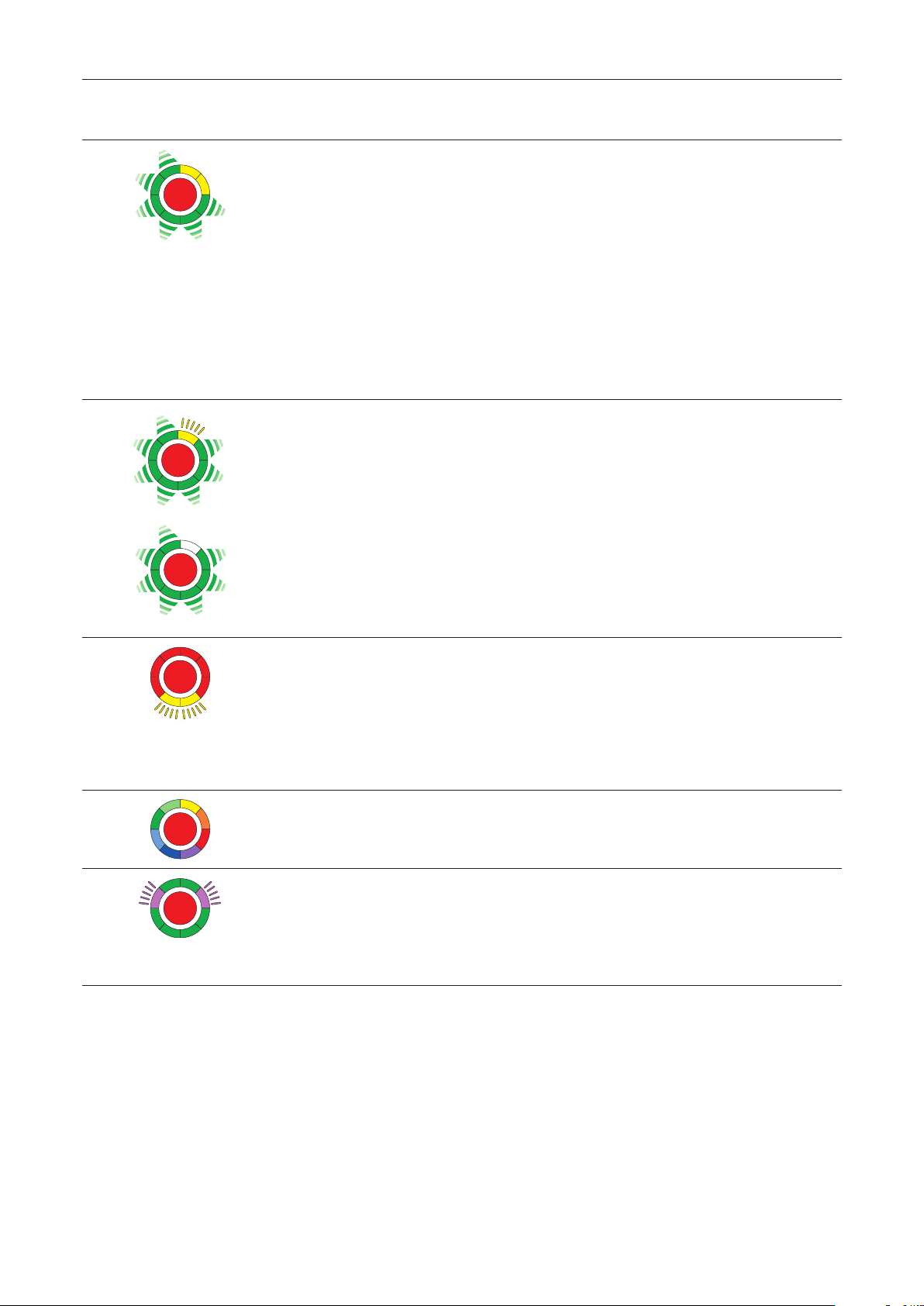
dormakaba System manual Troubleshooting
Signal
Cause Procedure
The alarm system reports an alarm
Alarm system has triggered via fire
detector or smoke switch or there is
an open circuit/short circuit to fire
detector or smoke switch.
1. Reset to fire detector or smoke
switch.
‣ The alarm is automatically*
acknowledged.
→The door lock locks.
The emergency button is pressed
The locking device does not lock.
1. Push and hold the key to the right
on the key switch.
2. Press the emergency button for 1s
and then release.
3. Push the key over the middle to the
left and bring it back to the middle
position.
4. Remove the key.
→The electric locking device is
active.
The emergency button is faulty
Internal emergency button error.
1. Push and hold the key to the right
on the key switch.
2. Press the emergency button for 1s
and then release.
3. Push the key over the middle to the
left and bring it back to the middle
position.
4. Remove the key.
→The electric locking device is
active.
If the error occurs again, replace the
device.
When locked
When permanent open
The connection via DCW® bus to a
standard DCW® node is interrupted
A standard DCW® component** is
missing/defective or SCU emergency
buttons signal that the SCU control
center is missing or defective.
1. Check the DCW® connection to the
DCW® component.
2. Reset the components table with
the TMS Soft or perform new
configuration.
Attention: Parameter settings
changed by TMS Soft® are lost!
If the error persists: Replacement of the
non-safety-related DCW® component.
*Depending on the parameterization, manual acknowledgment may also be required.
**I/O module DCW®, key switch STxx DCW®, SVP lock SVP 2xxx DCW®, smoke switch RS DCW®
10 SafeRoute® System 2019-03
WN 059722 45532
dormakaba TroubleshootingSystem manual
Signal
Cause Procedure
in addition, an alarm
signal sounds
The connection to an SCU emergency
button is interrupted
The electrical lock is deactivated.
or
The door is not closed.
or
The door contacts on the STV are not
connected.
1. Check the line to the SCU
emergency button.
2. Acknowledge the error after
removal.
3. Press the key switch to the right
and then to the left.
→The STVxxx locks.
or
4. Replace the defective SCU
emergency button
Missing or defective STV-xxx
STV-xxx is missing or the connection is
broken, e.g. plug disconnected
(Fig. shows Address 1 as an example)
The communication between SCU
and STV-xxx was interrupted (e.g. due
to a loose connection).
1. Check the line to STV address1.
2. Acknowledge the error after
removal.
3. Press the key switch to the right
and then to the left.
→The STVxxx locks.
Maintenance is required
The maintenance interval has been
exceeded.
1. Conduct maintenance (or order it)
according to specifications.
2. Reset the maintenance alarm. To
do this, press the key switch to the
left for 15 seconds or set a new
maintenance interval with TMS
Soft (as of license standard).
The unit is not configured 1. Check the components.
2. Carry out a new configuration.
The unit is supplied with over/
undervoltage.
The power supply does not meet the
requirements or specifications.
1. Check the power supply.
2. If the voltage drop on the supply
cable is too high, select a larger
cable cross-section or place an
additional power supply.
*Depending on the parameterization, manual acknowledgment may also be required.

11SafeRoute® System 2019-03WN 059722 45532
dormakaba System manual Replacement and removal of components
8 Replacement and removal of
components
The replacement and removal of components
connected to the SCU is performed in accordance
with the relevant assembly instructions. For safety-
related components, such as e.g. electrical door
locks STV xxx or SCU control units, the replacement
must be documented in the door unit’s inspection
log. The SafeRoute® system must then also be re-
commissioned.
Replacing DCW® components
When exchanging standard DCW® components, the
DCW® address and thus the set parameters can be
adopted. For a permanent removal from the bus
system, additional steps must be taken.
Replacing license cards
The replacement of the license card must be done
within 2 minutes. Any loaded applications are
permanently stored on the SLI license card. After
replacement, any necessary applications must be
reloaded.
8.1 Replace non-safety related DCW®
components
TIPS AND RECOMMENDATIONS
If the replaced component’s DCW® address
is retained, the set parameters are adopted.
1. Disconnect the wiring to the component.
2. Replace the defective component.
3. Take over the defective component’s DCW®
address (DIP switch).
4. Reconnect the wiring to the component.
→The component is incorporated in the system.
8.2 Remove non-safety related DCW®
components completely
1. Disconnect the wiring to the component.
2. Remove the component.
3. Delete the component from the system. To do
this, update the internal DCW® table (see chap.
8.4).
→The component is completely removed from
the system.
8.3 Replace/remove safety-related DCW®
components
1. Use TMS Soft®to read the current parameters (if
parameterized).
2. Disconnect the wiring to the component.
3. Replace/remove the component.
4. Take over the replaced component’s DCW®
address (DIP switch).
5. Reconnect the wiring to the component.
6. Carry out a new configuration.
7. Transfer parameter settings changed by TMS
S o f t ®.
→The component is incorporated in the system.
8.4 Update internal DCW® table
TIPS AND RECOMMENDATIONS
Attention: Parameter settings changed by
TMS Soft® are lost during configuration!
Before configuring with TMS Soft, read out
the current parameters (if parameterized)
and transfer again after configuration.
1. Reset the components table with TMS Soft®.
→The internal DCW® table is updated.
or
2. Carry out a new configuration.
→The internal DCW® table is updated.
8.4 Reset configuration to factory settings
TIPS AND RECOMMENDATIONS
Alternatively, the configuration can also be
done with the configuration software.
1. Press the S4 service button for 8 s.
‣ All default values are loaded.
2. Carry out a new configuration.
→All parameters are reset to the factory
settings.

12 SafeRoute® System 2019-03
WN 059722 45532
dormakaba MaintenanceSystem manual
9 Maintenance
The facility operator commissions the maintenance.
Maintenance is periodic and is performed by service
technicians authorized by dormakaba.
Customer service
dormakaba Service can be reached at the toll-free
number.
E-mail: [email protected]om
Fax: +49 2333 793-3777
dormakaba
SERVICE
24 h HOTLINE
0800 - 5240246
Other contact options:
• dormakaba - Technical Competence Center
Tel.: +49 2333 7932900
• Online repair order: www.dormakaba.com
dormakaba Service App for smartphone/tablet: Apple
iOS Appstore or Google Android Playstore
10 Disassembly, recycling and
disposal
Disassembly is carried out in the reverse order of
mounting and must be carried out by qualified
personnel.
The product must be disposed of in an
environmentally friendly manner. Electro-
technical parts and batteries must not be
disposed of as domestic waste. Dispose of
electrotechnical parts and batteries in the designated
acceptance and collection points. Refer to the
statutory regulations for your country.
11 Manufacturer's declarations
and test certificates
Any required documents, such as e.g. the EC
Declaration of Conformity, the manufacturer's
Declaration of Conformity, and compatibility lists, are
available at www.dormakaba.com .

13SafeRoute® System 2019-03WN 059722 45532
dormakaba System manual Annex
12 Annex
SLI
Mini
SLI
Basic
SLI
Standard
Release Via emergency button (with alarm trigger) ○ ○ ○
Unlock Via key switch(without alarm trigger)
– Temporary unlocking ○ ○ ●
– Long-term unlocking - - ●
– Permanent unlocking ○ ○ ○
– Operating time of the key switch for triggering the
unlocking type long-term permanent unlocking
- - ●
– Combination function short-term, long-term, permanent
unlocking: one of the different unlocking types can be deactivated
- - ●
Automatic unlocking at defined times of day (timer) - - ●
By alarm system (fire, danger, smoke detectors, sprinklers, etc.) ○ ○ ○
Bi-directional escape route - ○ ○
From outside to inside via external analog ST (key switch) ○ ● ●
From outside to inside via external DCW® ST or SVP / M-SVP xx - ● ●
Lock Automatic relocking
– After temporary unlocking ○ ○ ●
– After long-term unlocking - - ●
– If door was not opened after pressing the emergency button 1) - ● ●
– After closing - - ●
Automatic locking at defined times of day (timer) - - ●
Automatic relocking after power cut ○ ○ ○
Resetting the unlocking via key/emergency button ○ ● ●
Direct connection of motor locks
SVP 2xxx DCW®/ M-SVP 22xx DCW®
- ● ●
Vis./Aud. display Status/Warning/Initialization display on the illuminated ring.
– Adjusting the brightness - ● ●
– Adjusting the flashing frequencies - - ●
Pre-alarm/main alarm after temporary unlocking and
long-term unlocking
○ ○ ●
Maintenance alarm ○ ○ ●
Acoustic confirmation when activating
long-term or permanent unlocking
○ ○ ●
Alarm duration limit ○ ● ●
Alarm management (activation/deactivation of alarms) - ● ●
Monitoring Tamper monitoring (can be deactivated for maintenance purposes) ● ● ●
“Door open” monitoring ○ ○ ●
Two different time ranges for
the “door open” monitoring’s pre-alarm and main alarm
- - ●
Entry control Access control via keypad, e.g. STD-UP touchscreen display - - ●
History memory with date and time stamp - - ○
Networking LON - ● ●
LAN - ○ ○
Miscellaneous Automatic reactivation after power cut ○ ○ ○
Parameterization/visualization/control via TMS Soft® - ● ●
Freely programmable inputs/outputs on the SCU - ● ●
Additional programmable inputs/outputs via SIO-DR or I/O DCW® - - ●
Application cards
SLI-A
Multi-door control - ■ ■
Interlock control - ■ ■
Logic functions - - ■
Time-Delayed Release 1) - ■ ■
– one time delay step (parameterizable) - ■ ■
-not available ○available, not parameterizable ●available and parameterizable ■ with app
1) EN 13637 function

14 SafeRoute® System 2019-03
WN 059722 45532
dormakaba MaintenanceSystem manual

15SafeRoute® System 2019-03WN 059722 45532
dormakaba System manual Maintenance

www.dormakaba.com
Translation of the original document, subject to change without notice
dormakaba Deutschland GmbH
DORMA Platz 1
58256 Ennepetal
Germany
T: +49 2333 793-0
F: +49 2333 793-4950
Table of contents
Other Dormakaba Safety Equipment manuals


