pg. 2
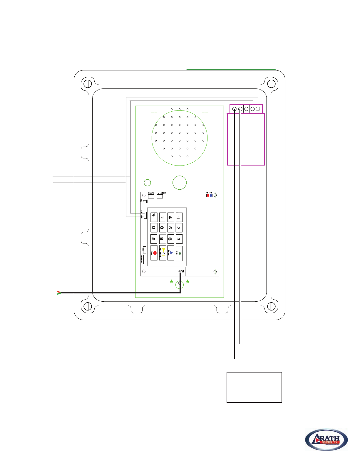
Call Box Installation – Without Optional Strobe
1. Attach mounting feet to the Call Box using supplied hardware.
2. Mount Call Box to the wall or pole using anchor screws.
3. Drill holes in appropriate locations in the Call Box for the electrical power and phone cable.
4. Attach conduit to the Call Box if appropriate for the install.
5. Run the 110/120 VAC electrical wires to the Call Box and attach to the power supply wiring using
appropriate wire nuts. See Drawing on Page 3.
6. Run the phone line to the Call Box. Connect a modular jack to phone cable and plug the Rath
supplied modular cable into the jack. Or, connect a modular RJ11 plug onto the phone cable
and attach directly to the RJ11 jack on the SmartPhone.
7. Turn on the electrical power.
8. Phone will now need to be programmed. If programming on-site, do not attach call box lid and
and proceed to “On-Site Programming”. See Page 5.
9. If programming remotely, attach the box lid and proceed to “Remote Programming”. See Page 5.
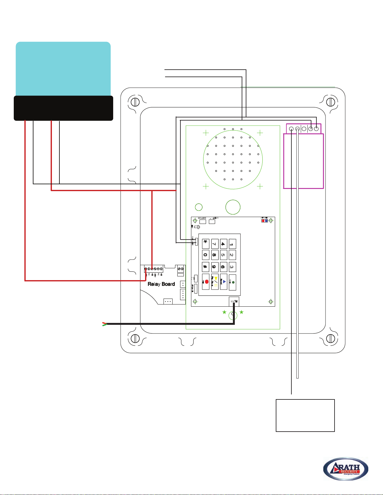
Call Box Installation – With Optional Strobe
1. Attach mounting feet to the Call Box using supplied hardware.
2. Mount Call Box to the wall or pole using anchor screws.
3. Mount strobe to the wall or pole using anchor screws.
4. Drill holes in appropriate locations in the Call Box for the electrical power and phone cable.
5. Attach conduit to the Call Box if appropriate for the install.
6. Run the 110/120 VAC electrical wires to the Call Box.
7. Run two wires from the Call Box to the strobe.
8. Attach the wires to the strobe using two wire nuts.
9. Connect the neutral of the incoming power to the white wire of the strobe and the transformer.
10. Connect the hot incoming wire to the transformer and the NO terminal on the Relay Board.
See Drawing on Page 4.
11. Connect the black wire of the strobe to the COM terminal on the Relay Board.
12. Run the phone line to the Call Box. Connect a modular jack to phone cable and plug the Rath
supplied modular cable into the jack. Or, connect a modular RJ11 plug onto the phone cable
and attach directly to the RJ11 jack on the SmartPhone.
13. Turn on the electrical power.
14. Phone will now need to be programmed. If programming on-site, do not attach call box lid and
proceed to the “On-Site Programming” section. See Page 5.
15. If programming remotely, attach the box lid and proceed to “Remote Programming”. See Page 5.
Items Needed (Provided by Rath):
• Anchor screws for mounting Call Box
•
Electrical conduit – For 110/120 VAC power
and strobe light
•
¼” driver – For snake eye security screw bit
• Wire nuts for connecting AC
Items Needed (Not Provided):
• Yellow Fiberglass Call Box
• Rath SmartPhone
• Back-up battery
• Power supply
• Blue strobe (optional)
• Snake eye security screw bit
www.rathsecurity.com
2100-986 Emergency Call Box