Dormakaba PAXOS advance IP User manual

Operating Manual
Doc. No.: OM_PAXOS_V005_20190222_EN EN
Redundant Lock
Order No: B02-M-08-XX
Firmware:
Made in Switzerland
Bus A
Bus Connectors Door Bolt
Contacts
Bus B Bus A Bus B
by Kaba AG, CH-8623 Wetzikon
110.90.01.10
Serial No: 40826114C
A - OUT B - OUT
A - IN B - IN
VdS
VdS 2396 (EN1300)
Class 2(B) w/Keypad: M101307
Class 3(C) w/Dial Knob: M101308
7
PRS
8
TUV
9
WXY
CLR
ENTER
4
GHI
5
JKL
6
MN
1
PRS
2
ABC
0
OQZ
3
DEF
advance IP

This documentation may not be reproduced in any way or otherwise used without the written consent of
dormakaba Schweiz AG.
Kaba® and PAXOS®advance are registered trademarks of dormakaba Schweiz AG.
Copyright by dormakaba Schweiz AG 2019
Doc. OM_PAXOS_V005_20190222_EN
Manufacturer
dormakaba Schweiz AG
Mühlebühlstrasse 23, Postfach
8620 Wetzikon
SWITZERLAND
www.dormakaba.com
Sales:

PAXOSadvanceIP OM_PAXOS_V005_20190222_EN 3
Operating Manual Table of Contents
Table of Contents
1 About this Operating Manual 6
1.1 To the beginning 6
1.2 Validity/Limitation 6
1.3 Target group 6
1.4 Additional documentation 6
1.5 Information and warning symbols 7
1.5.1 Danger to personnel 7
1.5.2 Danger to property 7
1.5.3 Other notes 7
1.6 Marks and denitions in the text 7
2 Safety and Environment 8
2.1 Intended use 8
2.2 General 8
2.3 Personnel qualication 8
2.4 Inadmissible equipment modications 8
2.5 Disposal 9
3 Product Description 10
3.1 Description of the system 10
3.2 Intended purpose 12
3.3 Technical data 13
3.3.1 Input unit with keypad 13
3.3.2 Input unit with dial knob 14
3.3.3 Lock 15
3.3.4 I/O-Box 16
3.3.5 IP-Box 16
3.4 Compliance/standards and regulations 17
4 Operation 18
4.1 Operating and display elements of the input unit 18
4.1.1 Operating and display elements of the keypad input unit 18
4.1.2 Operating and display elements of the dial knob input unit 19
4.2 Waking up the input unit/standard mode display 20
4.3 Status messages in the standard mode display 20
4.4 Code input/error messages when entering the code 22
4.4.1 Code input 22
4.4.2 Error messages during code input 23
4.5 Opening the locks 24

4 OM_PAXOS_V005_20190222_EN PAXOSadvanceIP
Table of Contents Operating Manual
4.5.1 Opening the door locks 25
4.5.2 Opening the inner compartment locks 27
4.6 Closing the locks 29
4.6.1 Closing the inner compartment locks 29
4.6.2 Closing the door locks 30
4.7 Enabling Fast Locking 31
4.8 Enabling aTime Lock Delay 32
4.9 Setting the contrast, brightness and dialog language 33
5 Conguring the System 35
5.1 Overview of setting parameters 35
5.2 Code functions 37
5.2.1 General information on the codes 37
5.2.2 Standard code types 37
5.2.3 Code formats 40
5.2.4 Setting new codes 40
5.2.4.1 Setting the Opening Code OCa.., OCb.. and Master Code 41
5.2.4.2 Dening new codes (e.g. additional Opening Codes, Time Codes,
Mutation Codes, Net codes, etc.) 45
5.2.5 Deleting or changing existing codes 47
5.3 Time functions 50
5.3.1 General information on the time functions 50
5.3.2 Setting the current date and time 51
5.3.3 Setting, changing, deleting a Holiday Locking Period 53
5.3.4 Setting, changing, deleting a Yearly Locking Period 57
5.3.5 Setting, changing and deleting a Weekly Locking Period 61
5.3.6 Setting, changing and deleting a Time Lock Override 65
5.3.7 Setting, changing and deleting Partial Locking 69
5.3.8 Setting/disabling Opening Delays 73
5.3.9 Setting/Disabling Duress Delays 75
5.3.10 Setting/disabling the Conrmation Window 77
5.3.11 Setting/disabling the Return Lock 79
5.3.12 Setting, changing and deleting Summer/Winter Time Changeover 81
5.4 Settings 85
5.4.1 General information on the settings 85
5.4.2 Dene basic settings for the locks 86
5.4.2.1 Enabling/disabling Duress Code 86
5.4.2.2 Setting Fast Locking times 88
5.4.2.3 Setting a Time Lock Delay 90
5.4.2.4 Setting the date and time format 92
5.4.2.5 Setting the Locking Mode 94
5.4.2.6 Enabling/disabling the Show time lock end 96

PAXOSadvanceIP OM_PAXOS_V005_20190222_EN 5
Operating Manual Table of Contents
5.4.2.7 Enabling/disabling the Remote Lock function 98
5.4.2.8 Enabling/disabling Parallel Mode 100
5.4.2.9 Enabling/disabling Dual Mode 102
5.4.2.10 Setting the Maximum Open Period 104
5.4.3 Dening basic settings for the input unit 106
5.4.3.1 Setting the dialog language, brightness and contrast of the display 106
5.4.3.2 Setting the signal volume 108
5.4.3.3 Setting the content of the battery compartment 109
6 Querying System Information 111
6.1 Querying system information over the Info menu 111
6.1.1 Accessing the Info menu 111
6.1.2 Querying the system settings 112
6.1.3 Querying lock information 113
6.1.4 Querying information of an input unit 114
6.1.5 Querying information on the I/O-Box 115
6.1.6 Querying information on the IP-Box 116
6.2 Querying locking periods 117
7 Maintenance 118
7.1 Notes on maintenance 118
7.2 Cleaning the input unit 118
7.3 Replacing the batteries/dormakaba rechargeable battery pack, Battery code 118
8 Operating errors 121
8.1 Error messages / Troubleshooting 121
8.2 Notes on troubleshooting 124
8.3 Customer Service 124
9 Appendix 125
9.1 Menu overviews for input unit 125
9.1.1 Operator menu 125
9.1.2 Info menu 126
9.2 Factory code / Demonstration code list 127
9.2.1 Factory code 127
9.2.2 Demonstration code list 127

PAXOSadvanceIP OM_PAXOS_V005_20190222_EN 7
Operating Manual About this Operating Manual
1 About this Operating Manual
1.1 To the beginning
The fully redundant electronic high-security locking system PAXOSadvanceIP (Paxos advance for
short) is designed in accordance with the latest technology and meets all known safety standards.
Nevertheless, improper operation of the electronic high-security locking system Paxos advance
can lead to material damage or physical injury.
To ensure asafe, proper and economical operation of the electronic high-security locking system
Paxos advance , observe and comply with all information and safety instructions in this manual
and the instructions for the components that are used together with the locking system.
If you have questions, which are not or insuciently answered in this Operating Manual, please
contact your supplier. They will be glad to assist you.
1.2 Validity/Limitation
This manual describes the operation and conguration of the electronic high-security locking
system Paxos advance.
The available options (I/O-Box, IP-Box, AS384 Management-Suite Software) are only described
insofar as required for the proper operation of the electronic high-security locking system Paxos
advance. Further information on the optional AS384 Management-Suite Software can be found
in the help function of the software.
1.3 Target group
This Operating Manual is intended for highly skilled and trained personnel, which are entrusted
with the operation and conguration of the electronic high security locking system Paxos ad-
vance.
The description presumes that trained personnel certied by dormakaba Schweiz AG are working
on the system and does not replace product training.
1.4 Additional documentation
This Operating Manual is supplemented by the Installation Instructions, the Quick Start Guide
and the Service Instructions for the electronic high-security locking system Paxos advance.

8 OM_PAXOS_V005_20190222_EN PAXOSadvanceIP
About this Operating Manual Operating Manual
1.5 Information and warning symbols
1.5.1 Danger to personnel
Risk of explosion!
Indicates potentially dangerous situation that in case of non-compliance may lead to minor
injuries.
1.5.2 Danger to property
CAUTION
Indicates apotentially dangerous situation which, if not heeded, might lead to system damage
or have signicant impact on the function and/or usage of the system.
1.5.3 Other notes
Application instructions with additional information. They ensure that the product and its func-
tions are used optimally.
A
S
3
8
4
AS384 Management-Suite Software
Refers to the AS384 Management-Suite Software (optional), which allows additional settings
and functions.
1.6 Marks and denitions in the text
– To enhance readability of the instructions, the “fully redundant electronic high-security lock-
ing system PAXOSadvanceIP” is shortened to “locking system“ or“Paxos advance“.
– Cross-references to other chapters with more detailed information about atopic are marked
in italics and set in parentheses.
Example: (see section 3 "Product Description")
– Text appearing in the display of the input unit is placed in quotation marks.
Example: “Unlocked”
– Keys that need to be pressed are marked in bold capital letters and set in angle brackets (ex-
ample: <ENTER>).

PAXOSadvanceIP OM_PAXOS_V005_20190222_EN 9
Operating Manual Safety and Environment
2 Safety and Environment
2.1 Intended use
The locking system Paxos advance is used for locking and releasing the mechanical locking points
of safe doors and inner compartment locks, which are generally operated manually via abolt-
work.
The release (open locks) is only executed after entering one or more of the opening codes on
the input unit. The opening of the lock can also be made dependent on time functions and/or
external signals.
The locking system Paxos advance must be used only for its intended purpose – blocking and
releasing mechanical blocking points of the above-mentioned equipment. Any use beyond this is
deemed to be improper. The manufacturer is not liable for any damages that result from such use.
The locking system Paxos advance is intended solely for use in closed rooms.
2.2 General
Any person entrusted with working on the locking system Paxos advance must read and under-
stand this manual before starting work.
Knowledge of the contents of the operating manual is aprerequisite for protecting sta from
dangers, avoiding faulty operation and thus operating the system safely and appropriately.
2.3 Personnel qualication
All actions described in this manual must be performed only by well trained and suciently quali-
ed personnel. It is assumed that this personnel knows all relevant external and internal regula-
tions that must be observed for the operation of the locking system Paxos advance.
For safety and warranty reasons, further interventions must be performed solely by personnel
authorised by the manufacturer.
2.4 Inadmissible equipment modications
Modications to the electronic high security locking system Paxos advance are expressly not rec-
ommended and can lead to the loss of warranty and certication (e.g. VdS certication) and aect
the security of the system.
Defective system components may be replaced only with original parts from your supplier and
only by authorized personnel.
10 OM_PAXOS_V005_20190222_EN PAXOSadvanceIP
Safety and Environment Operating Manual
2.5 Disposal
Packaging
Environmentally-friendly disposal of packaging
The system components are supplied in recyclable packaging. Please do not dispose of packag-
ing in the household waste or the environment, but have them recycled instead.
System components
Do not dispose of system components in the household waste or the environment
At the end of the service life or in case of replacement, the system components must be re-
turned to dormakaba Schweiz AG or taken to adisposal or recycling point, in accordance with
the locally applicable regulations. Under no circumstances may system components be dis-
posed of in the environment.
Batteries/rechargeable batteries
No not dispose of used batteries/rechargeable batteries in the household waste or the
environment
Used batteries/rechargeable batteries are to be disposed or taken to arecycling point, in ac-
cordance with state and local regulations. Under no circumstances may batteries be disposed
of in the household waste or the environment.
Carefully store the batteries/dormakaba rechargeable battery packs to be disposed of in order
to avoid short circuits, squeezing, or destruction of the battery/rechargeable battery casing.

PAXOSadvanceIP OM_PAXOS_V005_20190222_EN 11
Operating Manual Product Description
Redundant Lock
Order No: B02-M-08-XX
Firmware:
Made in Switzerland
Bus A
Bus Connectors Door Bolt
Contacts
Bus B Bus A Bus B
by Kaba AG, CH-8623 Wetzikon
110.90.01.10
Serial No: 40826114C
A - OUT B - OUT
A - IN B - IN
VdS
VdS 2396 (EN1300)
Class 2(B) w/Keypad: M101307
Class 3(C) w/Dial Knob: M101308
7
PRS
8
TUV
9
WXY
CLR
ENTER
4
GHI
5
JKL
6
MN
1
PRS
2
ABC
0
OQZ
3
DEF
3 Product Description
3.1 Description of the system
Basic version
In the basic version, the fully redundant electronic high-security locking system Paxos advance
consists of an input unit (with keypad or dial knob), one or more door locks and, optionally, mul-
tiple inner compartment locks, which are interconnected via aredundant Bus system. In the basic
version, the system is supplied by abattery pack with six alkaline or lithium batteries of type AA.
Each of the two redundant door bolt contacts, connected to door lock 1 and each inner compart-
ment lock (customer must install), signal to the system whether the door locks or an inner com-
partment lock is open or closed.
Input unit with keypad
Battery pack
Door lock 1
Door lock 2
Door lock 3
Door bolt contacts
Inner compartment lock 1
Door bolt contacts
Inner compartment lock n
Door bolt contacts
System overview basic version
Input unit with dial knob
Battery pack

12 OM_PAXOS_V005_20190222_EN PAXOSadvanceIP
Product Description Operating Manual
The locking system Paxos advance provides powerful functions for application in high security
areas (e.g. dierent types of code with dierent access privileges, dual mode, duress code, open-
ing delay, locking period functions, etc.). In the basic version, operation and conguration of the
system take place via the input unit. Optionally, the system can also be programmed and man-
aged via the AS384 Management-Suite Software.
The basic model can be extended optionally with up to two additional input units, and up to
three optional I/O-Boxes and an IP-Box. amaximum of 12 system components (locks, input units,
I/O-Boxes, IP-Box) can be interconnected over the redundant Bus system.
Option I/O-Box
The optional I/O-Box is integrated into the locking system via the redundant Bus system.
The I/O-Box features 8 inputs and outputs for enhanced alarm and safety functions, and ter-
minals for connection of an external voltage source. The function of the inputs and outputs are
factory preset and can be assigned individually only with the AS384 Management-Suite Software.
If the I/O-Box is connected to a non-failsafe power supply, the battery compartment of the
input unit must necessarily have abattery/rechargeable battery pack, which ensures voltage
supply to the system when the power fails. The input unit control automatically detects whether
abattery pack is inserted in the battery compartment and charges it while operating on an exter-
nal power source.
If the I/O-Box is connected to an uninterruptible power supply (UPS), abattery/rechargeable bat-
tery pack does not need to be inserted in the battery compartment of the input device.
Option IP-Box
The optional IP-Box is integrated into the locking system via the redundant Bus system.
The IP-Box serves as network interface and features 3 inputs and outputs to control additional
functions, and terminals for connection of an external voltage source. The function of the inputs
and outputs are factory preset and can be assigned individually only with the AS384 Manage-
ment-Suite Software.
If the IP-Box is connected to anon-failsafe power supply, the battery compartment of the in-
put unit must necessarily have abattery/rechargeable battery pack, which ensures voltage
supply to the system when the power fails. The input unit control automatically detects whether
abattery pack is inserted in the battery compartment and charges it while operating on an exter-
nal power source.
If the IP-Box is connected to an uninterruptible power supply (UPS), abattery/rechargeable bat-
tery pack does not need to be inserted in the battery compartment of the input device.

PAXOSadvanceIP OM_PAXOS_V005_20190222_EN 13
Operating Manual Product Description
Option AS384 Management-Suite Software
The AS384 Management-Suite Software provides access to advanced functions of the locking
system Paxos advance (e.g. denition of time-controlled locking periods, setting of codes with
individual authorisations, code proles and code prole groups, reading of audit data as well
as export and import of audit les, etc.), thus allowing the creation and management of custom
solutions. In addition, multiple Paxos advance locking systems may be managed with the AS384
Management-Suite Software, either via the USB interface or via an IP network.
Operational modes
The locking system Paxos advance can be operated in two dierent modes:
– Stand-alone mode (code format: PIN only, for lock class 4 (EN1300) or D (VdS 2396) the code
format is always ID+PIN)
Conguration of the locking system is done exclusively via the control software of the input
unit.
– Extended mode (code formats: PIN only or ID+PIN)
The conguration of the locking system is done via the optional AS384 Management-Suite
Software.
3.2 Intended purpose
The locking system Paxos advance serves to block and release mechanical blocking points of se-
cure storage doors and inner compartment locks.
The locking system Paxos advance oers awide range of high-security applications. It allows the
programming of dierent codes and code combinations, time dependent functions, etc., for ac-
cessing and programming the system.
Programming is done via the input unit (stand-alone mode) or via acomputer which runs the
AS384 Management-Suite Software and is connected by USB cable to the input unit (extended
mode) or via network and AS384 Management-Suite Software.
The locking system Paxos advance is especially suitable for applications where high security, mul-
tiple users, traceability and exibility are required. The consistent redundancy of the system com-
ponents guarantees high reliability of the locking system.

14 OM_PAXOS_V005_20190222_EN PAXOSadvanceIP
Product Description Operating Manual
3.3 Technical data
3.3.1 Input unit with keypad
Dimensions (HxWxD) 137x135x60 mm
Weight (without batteries/rechargeable batteries and mounting
bracket)
410 g
Material ABS injection moulded
Fastening With mounting bracket and 2 M6 screws
Electrical connection to the locking system Redundant bus cables (Bus aand Bus B)
Display LCD with backlight, graphic 122 x 32 pixels (2 lines)
Dialog language German, English, French, Italian, Spanish
and others
Input Keypad (14 keys)
Identication mark code 0...9 and/or A...Z
Number of code positions 8 characters/digits
Number of code combinations 100'000'000 (100 million)
Batteries 6x alkaline or lithium 1,5 V,
Type “Minion”, “AA”, “LR6”, “E91” or “AM3”
Rechargeable batteries Paxos rechargeable battery pack 9V Ni-MH 302011
Operating voltage 9 VDC
Power consumption active / idle Max. 13 mA / 20 μA
Overvoltage protection Until 10 kV
Electro-magnetic compatibility (EMC) According to VdS 2110
Permissible temperature range of operation 0 °C ... +50 °C
Permissible temperature range of storage -10 °C ... +70 °C
Permissible ambient humidity Max. 75% RH, non-condensing
Certication mark CE
Safety class B (EN 1300), 2 (VdS 2396), UL

PAXOSadvanceIP OM_PAXOS_V005_20190222_EN 15
Operating Manual Product Description
3.3.2 Input unit with dial knob
Dimensions (HxWxD) 137x135x60 mm
Weight (without batteries/rechargeable batteries and mounting
bracket)
405 g
Material ABS injection moulded
Fastening With mounting bracket
Electrical connection to the locking system Redundant bus cables (Bus aand Bus B)
Display LCD with backlight, graphic 122 x 32 pixels (2 lines)
Viewing angle limitation Laterally ± 30°
Dialog language German, English, French, Italian, Spanish
and others
Input Dial/push knob, specifying arandom number
Identication mark code 0...9
Number of code points 8 characters
Number of code combinations 100'000'000 (100 million)
Batteries 6x alkaline or lithium 1,5 V,
Type “Minion”, “AA”, “LR6”, “E91” or “AM3”
Rechargeable batteries Paxos rechargeable battery pack 9V Ni-MH 302011
Operating voltage 9 VDC
Power consumption max. 33 mA
Overvoltage protection Until 10 kV
Electro-magnetic compatibility (EMC) According to VdS 2110
Permissible temperature range for operation 0 °C ... +50 °C
Permissible temperature range for storage -10 °C ... +70 °C
Permissible ambient humidity max. 75% RH, non-condensing
Certication mark CE
Safety class C/D (EN 1300), 3/4 (VdS 2396), UL

16 OM_PAXOS_V005_20190222_EN PAXOSadvanceIP
Product Description Operating Manual
3.3.3 Lock
Dimensions (HxWxD) 85.0 x 60.4 x 30.9 mm
Weight 440 g
Material Zamak die-cast zinc
Fastening 3 screws M6
Electrical connection to the locking system Redundant bus cables (Bus aand Bus B)
Fastening carrier adapter to boltwork 1 screw M5 or 2 screws M4
Boltwork Adjustable 8.7, 12, 14 or 15 mm
Bolt adjustment force nominal 30 N (in both directions)
Bolt counter force in adjustment direction (static) ≥ 1000 N
Code storage Flash (power failure protected)
Operating voltage 9 VDC
Standby current active/idle 11 mA / approx. 20 μA
Maximum motor activation current 660 mA
Overvoltage protection Until 10 kV
Electro-magnetic compatibility (EMC) According to VdS 2110
Permissible temperature range for operation 0 °C ... +50 °C
Permissible temperature range for storage -10 °C ... +70 °C
Permissible ambient humidity Max. 75% RH, non-condensing
Certication mark CE
Safety class B/C/D (EN 1300), 2/3/4 (VdS 2396):
- with Keypad Input Unit: B (EN 1300), 2 (VdS 2396)
- with Dial Knob Input Unit: C (EN 1300), 3 (VdS 2396)
- with Dial Knob Input Unit: D (EN 1300), 4 (VdS 2396)
- UL certied when lock distance to cable hole is at least 15 cm.
Note: The audit features, the software features, features
associated with peripheral devices and systems, optional
interconnect devices and their associated features, fea-
tures involving the use of user keys, the duress feature,
monitoring features, remote features, one time code
functionality and other additional features have not
been evaluated by UL.

PAXOSadvanceIP OM_PAXOS_V005_20190222_EN 17
Operating Manual Product Description
3.3.4 I/O-Box
Dimensions (HxWxD) 117 x 80,0 x 33,5 mm
Weight 186 g
Material housing Aluminium
Fastening 4 screws M5
Electrical connection to locking system Redundant bus cables (Bus aand Bus B)
Terminals for wire cross sections up to 1 mm2
Inputs 8
Outputs 8
Interface RS232
Connection of external power supply 12...24 VDC, 1 A
Operating voltage 12 VDC
Power consumption Max. 300 mA
Overvoltage protection Until 10 kV
Electro-magnetic compatibility (EMC) According to VdS 2110
Permissible temperature range for operation 0 °C ... +50 °C
Permissible temperature range for storage -10 °C ... +70 °C
Permissible ambient humidity Max. 75% RH, non-condensing
Certication mark CE
3.3.5 IP-Box
Dimensions (H x W x D) 120 x 100 x 36 mm
Weight 410 g
Material housing Sheet metal, galvanized
Fastening 4 M5 screws
Electrical connection with the locking system Redundant bus cables (Bus A and Bus B)
Terminals for wire cross sections up to 1 mm2
Inputs 3
Outputs 3
Interface Ethernet RJ45 10/100BaseT
Connection of external power supply 12...24 VDC, 1 A
Operating voltage 12 VDC
Power consumption Max. 300 mA
Overvoltage protection Up to 10 kV
Electro-magnetic compatibility (EMC) According to VdS 2110
Permissible temperature range for operation 0°C ... +50°C
Permissible temperature range for storage -10°C ... +70°C
Permissible ambient humidity Max. 75 %RH, non-condensing
Certication mark CE

18 OM_PAXOS_V005_20190222_EN PAXOSadvanceIP
Product Description Operating Manual
3.4 Compliance/standards and regulations
The Declaration of Conformity is delivered in aseparate document.
The fully redundant electronic high-security locking system Paxos advance complies with the
standards and regulations in accordance with the information provided in the Technical Data (see
section 3.3 "Technical data").

PAXOSadvanceIP OM_PAXOS_V005_20190222_EN 19
Operating Manual Operation
4 Operation
4.1 Operating and display elements of the input unit
4.1.1 Operating and display elements of the keypad input unit
7
PRS
8
TUV
9
WXY
CLR
ENTER
4
GHI
5
JKL
6
MN
1
PRS
2
ABC
0
OQZ
3
DEF
3
1
2
4
Keypad input unit
1 Two-line liquid crystal display (LCD)
2 Keypad with 10 numeric and 4 function
keys
3 USB port (connection to computer with
programming or audit software)
4 Battery compartment
Key functions
Keys Function
ENTER
Press briey–Conrming input
–Calling the user menu from the standard
mode display
CLR
Press briey–Deleting input
–Aborting afunction
–Returning to the previous menu level
Press briey–Selecting the next menu option
–Selecting the next input value
Press briey–Selecting the previous menu option
–Returning to the previous input value
7
PRS
8
TUV
9
WXY
4
GHI
5
JKL
6
MN
1
PRS
2
ABC
0
OQZ
3
DEF
Press briey Input of numbers
CLR
Press and hold down
key. Release key as
soon as the info menu
appears
Calling Info menu
20 OM_PAXOS_V005_20190222_EN PAXOSadvanceIP
Operation Operating Manual
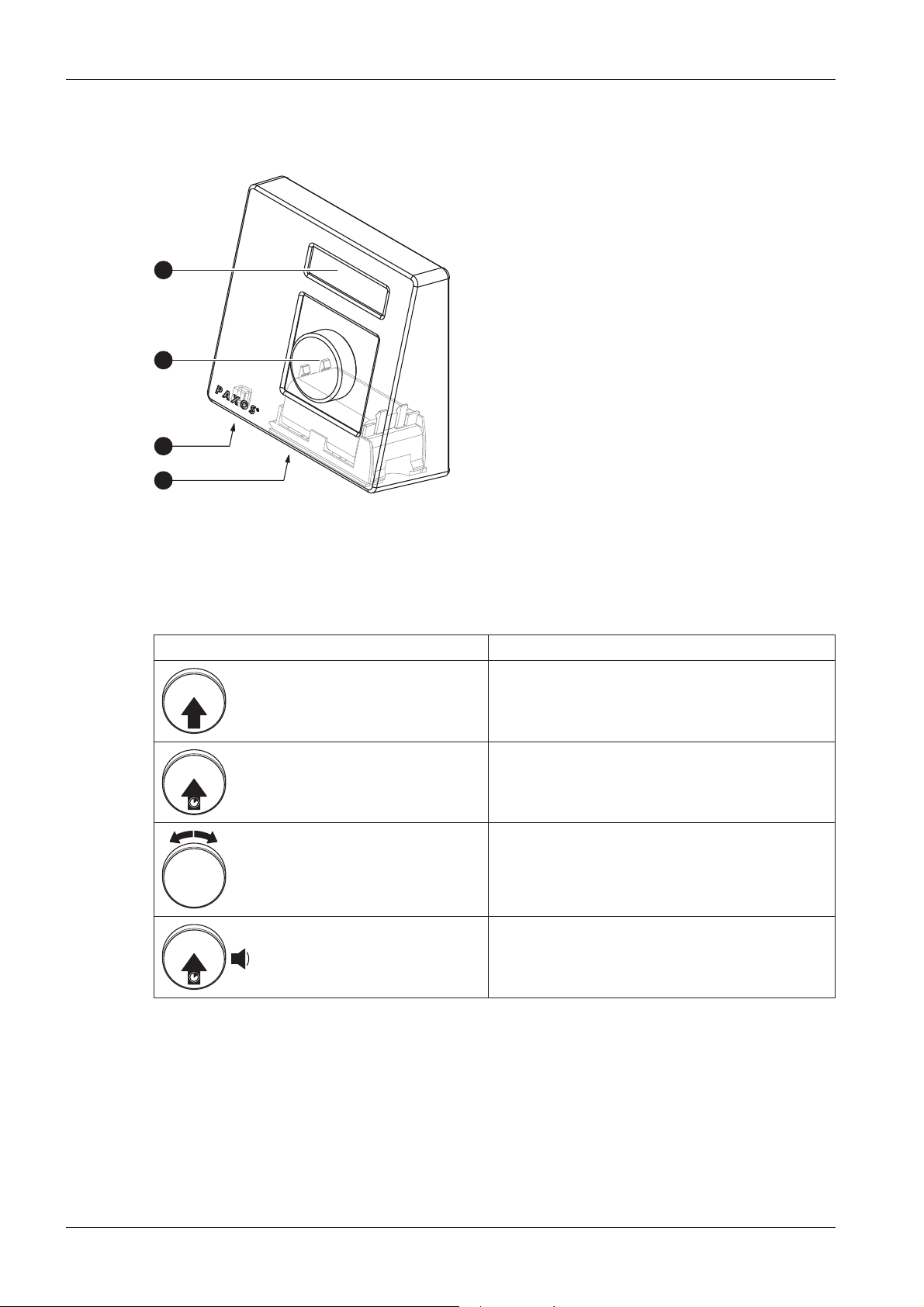
4.1.2 Operating and display elements of the dial knob input unit
3
1
2
4
1 Two-line liquid crystal display (LCD)
2 Dial knob
3 USB port (connection to computer with
programming or audit software)
4 Battery compartment
Dial knob input unit
Functions of the dial knob
Dial knob Function
Press dial knob briey. –Conrming input
–Calling the user menu from the standard
mode display
Press dial knob >1.5sec-
onds.
–Deleting input
–Aborting afunction
–Returning to the previous menu level
Turn dial knob left or right. –Selecting the next or previous menu option
–Selecting the next or previous input value
–Increasing or decreasing the value dis-
played
1x
Press and hold down key.
Release dial knob as soon
as the info menu appears
Calling Info menu

PAXOSadvanceIP OM_PAXOS_V005_20190222_EN 21
Operating Manual Operation
4.2 Waking up the input unit/standard mode display
Waking up the display of the input unit
The display of the input unit switches automatically o after 15seconds without action. To
wake up the display, press any key on the keypad input unit or press briey the knob of the dial
knob input unit.
Assuming the locking system has been put into operation and addressed properly (see installa-
tion instructions), the standard operating mode display appears after waking up the input unit.
In the standard mode display, the current date, current time, and the current status of the locking
system is shown (e.g. state“Secured”).
– If another status message is displayed, please follow the instructions in section 4.3 "Status mes-
sages in the standard mode display".
– If the display remains blank or an error message is displayed, please follow the instructions in
section 8 "Operating errors".
4.3 Status messages in the standard mode display
The door locks are unlocked and the boltwork is open.
By briey pressing the <ENTER> key or briey pressing the dial
knob you can access the user menu “Unlocked”.
The door locks are open and the boltwork is closed.
After opening the door locks, the message “Locks are open, open
bolt” appears for about 5 seconds. Then a sound signal and the
message “Open bolt” indicates that you should open the boltwork.
If the boltwork is not opened within acertain time, the door locks
will be closed automatically (with “Locking mode Automatic“)
or the message “Close with ENTER“ appears (with “Locking mode
Manual“).
The safe door is partly locked. The last door lock and boltwork are
closed.
By briey pressing the <ENTER> key or briey pressing the dial
knob you can access the user menu “Secured”.
The boltwork and the door locks are closed.
By briey pressing the <ENTER> key or briey pressing the dial
knob you can access the user menu “Secured”.
The locking system is locked via one of the locking time functions
(e.g. fast locking). The door locks cannot be opened until the lock-
ing time has expired. The date and time of the end of the locking
time are displayed.
By briey pressing the <CLR> key or by pressing the dial knob
>1.5seconds, the current date and current time are displayed for
about 5seconds.
Table of contents
Other Dormakaba Safety Equipment manuals


