AJAX MultiTransmitter User manual

MultiTransmitter User Manual
Updated December 29, 2020
MultiTransmitter is an integration module with 18 wired zones for connecting third-
party detectors to the Ajax security system. To protect against dismantling,
MultiTransmitter is equipped with two tampers. It is powered from the mains 100–
240 V AC, and can also run on a 12 V backup battery. It can supply 12 V power to
connected detectors.
MultiTransmitter operates as part of the Ajax security system by connecting via the
secure radio communication protocol to the hub. The hub communication
range is up to 2,000 meters provided there are no obstacles. If jamming or
interference is detected, the “high level of interference at Jeweller frequencies”
event is transmitted to the central monitoring station of the security company and
system users.
Jeweller
What jamming of a security system is

Not compatible with , , and third-party security central units
The device connects to the hub and is configured through on iOS,
Android, macOS, and Windows. All alarms and user events are reported by push
notifications, SMS, and calls if enabled. Ajax security system can be connected to
the central monitoring station of the security company. The list of authorized
partners is available .
Functional elements
Body elements
ocBridge Plus uartBridge
Ajax apps
here
Buy MultiTransmitter integration module
1. Screws securing the body lid. Unscrew with bundled hexagon key (Ø 4 mm)
2. Cavity for backup battery
Battery not included with MultiTransmitter set

MultiTransmitter card elements
3. QR code and ID/serial number of the device
4. Perforated part of the body. It is necessary for tamper triggering in case of
dismounting attempts
5. Perforated part of the body for the output of wires of connected detectors and
devices
1. Power supply terminals for fire detectors
2. Power supply input 110/230 V
3. Tamper button. Signals if MultiTransmitter body lid is removed
4. Terminals for connecting a 12 V backup battery
5. Power button
. LED indicator
7. QR code and ID/serial number of the device
. Terminals for connecting wired detectors (zones)

MultiTransmitter terminals
Left-hand terminals:
GND — MultiTransmitter common ground
+EXT — 12 V power supply output for fire detectors
COM — common input for connecting power supply circuits and signal contacts of
wired detectors
Right-hand terminals:
Z1–Z18 — input for wired detector сonnection
+12 V — 12 V power supply output for wired detectors
COM — common input for connecting power supply circuits and signal contacts of
wired detectors
LED indication

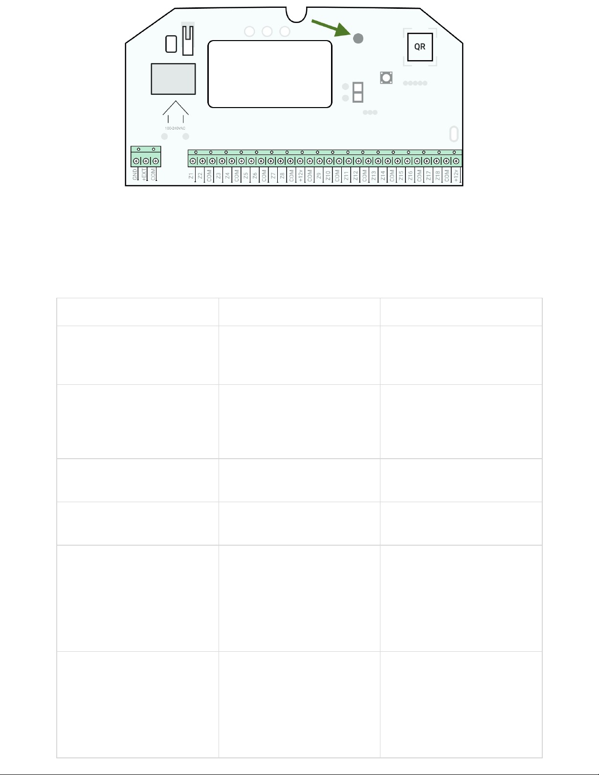
MultiTransmitter LED indicator may light up white, red, or green, depending on the
status of the device. Please note that the LED indicator is not visible when the body
lid is closed, but the status of the device can be found in the Ajax app.
LED indication Event Note
Lights white
Connection with the hub is
established, external power
supply is connected
Lights red
There is no connection with the
hub, external power supply is
connected
For example, the hub is turned
off or MultiTransmitter is
outside the coverage area of the
hub’s wireless network
Goes out for 0.5 seconds, then
lights up green and turns off
Switching off the
MultiTransmitter
Blinks red once per second MultiTransmitter is not
assigned to the hub
Lights up for a second once
every 10 seconds
No external power supply is
connected to MultiTransmitter
Lights up white if there is
connection with hub.
Lights up red if there is no hub
connection
During an alarm, gradually lights
up and goes out once every 10
seconds
No external power supply and
discharged external battery of
MultiTransmitter
Lights up white if there is
connection with hub.
Lights up red if there is no hub
connection

If MultiTransmitter is not assigned to the hub or has lost connection with it, the integration
module will not give an indication of the battery status or the presence of external power
supply.
Operating principle
MultiTransmitter is designed for connecting third-party wired detectors and devices
to the Ajax security system. The integration module receives information about
alarms and triggering of detector tampers via wires connected to the terminals.
MultiTransmitter can be used to connect panic and medical alarm buttons, indoor
and outdoor motion detectors, as well as detectors tracking opening, vibration,
breaking, fire, gas, leakage, etc. The type of device is indicated in the zone settings.
The text of notifications about alarms and events of the connected device, as well
as event codes transmitted to the Central Monitoring Station (CMS) of the security
company depend on the selected device type.
A total of 6 types of devices are available:
Type Icon
Tamper

Intrusion alarm
Fire alarm
Medical alarm
Panic button
Gas concentration alarm

MultiTransmitter has 18 wired zones. The number of connected devices depends
on their power consumption. The total maximum current consumption of all
connected devices or detectors is 1 A.
Supported connection types:
Designation Type
NO Normally open
NC Normally closed. Without resistors
EOL (NC with resistors) Normally closed. With resistors
EOL (NO with resistors) Normally open. With resistors
The integration module has 3 power supply lines of 12 V: one dedicated line for fire
detectors and two — for other devices.
After the fire alarm, fire detectors need a power reset to restore normal operation. Therefore,
the fire detectors power supply should only be connected to a dedicated line. Also, avoid
connecting other detectors and devices to power terminals of fire detectors as this may lead
to false alarms or incorrect operation of the devices.
Event transmission to the monitoring station
Ajax security system can connect to the CMS and transmit alarms to the
monitoring station in Sur-Gard (ContactID) and SIA protocol formats.
The loop (zone) number of the integration module and the devices connected to it
can be found in Ajax apps, in the Groups menu of the hub settings.
To learn the loop (zone) number, select the group in which the integration module
is located or the desired connected device. The Device Number (or DeviceIndex in
) corresponds to the loop (zone) number.
Connecting to the hub
Ajax PRO Desktop

For the Ajax security system, MultiTransmitter acts as a single device and each
connected device or detector occupies a single slot in the limited number of the
hub devices — 100 in and , 150 in , and 200 in .
Wired detectors can be connected to MultiTransmitter both before and after connecting the
module to the hub.
Before starting connection
Only users with administrator rights can add MultiTransmitter to the hub.
In order to connect MultiTransmitter
Hub Hub 2 Hub Plus Hub 2 Plus
1. Install the . . Add a hub to the app and create at
least one room.
Ajax app Create an account
2. Check that the hub is on and has access to the internet (via Ethernet cable, Wi-
Fi, and/or mobile network). You can do this in the Ajax app or by looking at the
hub logo on the front panel. The logo should light up white or green if the hub is
connected to the network.
3. Ensure that the hub is disarmed and does not start updates by checking its
status in the app.
1. Go to the Devices tab in the Ajax app and click Add Device.
2. Name the integration module, scan or enter the QR code manually (located on
the body and packaging), and select the placement room.
3. Click Add; the countdown will begin.
4. Turn on MultiTransmitter by holding the power button for 3 seconds. Keep in
mind that the request to connect to the hub is transmitted only when the
integration module is turning on.

For the detection and pairing to occur, the integration module should be located within the
coverage area of the hub’s wireless network (at the same guarded object).
If the connection has failed, disconnect MultiTransmitter for 5 seconds and try
again.
If the integration module has already been assigned to another hub, turn off the
integration module, and then follow the standard addition procedure.
The connected integration module will appear in the app, in the hub’s list of
devices. Updating device statuses in the list depends on the ping time defined in
Jeweller settings. The default value is 36 seconds.
MultiTransmitter states
Icons
Icons display some of the MultiTransmitter states. You can view them in the Ajax
app, in the Devices tab .
Icon Value
Jeweller signal strength — displays the signal strength between the hub and
MultiTransmitter
A fire detector connected to MultiTransmitter has registered an alarm
MultiTransmitter battery charge level
MultiTransmitter has a malfunction. The list is available in the integration module
states
MultiTransmitter works through a ReX radio signal range extender
States
Table of contents
Other AJAX Safety Equipment manuals
Popular Safety Equipment manuals by other brands

Lanex
Lanex PB-20 instruction manual

SKYLOTEC
SKYLOTEC ANCHOR ROPES Instructions for use

Besto
Besto Buoyancy Aid 50N Instructions for use

TEUFELBERGER
TEUFELBERGER NODUS Manufacturer's information and instructions for use

Troy Lee Designs
Troy Lee Designs Tbone Product owners manual

Innova
Innova Xtirpa Instruction and safety manual

bolle SAFETY
bolle SAFETY B810 quick start guide

SHENZHEN FANHAI SANJIANG ELECTRONICS
SHENZHEN FANHAI SANJIANG ELECTRONICS A9060T instruction manual

Hiltron security
Hiltron security POWER8E Installation and use manual

Salewa
Salewa MTN SPIKE user manual

Hatco
Hatco B-950P installation guide

Sitec
Sitec TX MATIC operating manual


