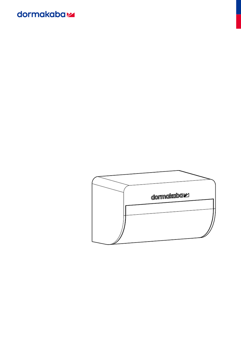
Dormakaba M A01 User manual

DE
Radarsensor M A01
060616 45532/16707 - 2023-04 1/8
Informationen zu diesem Dokument
Inhalt und Zweck
Der Inhalt dieser Kurzanleitung ist ein Auszug aus der vollständigen
Anleitung und beschränkt sich auf wichtige Informationen zum Pro-
dukt und dessen Inbetriebnahme. Die vollständige Anleitung ist
über den QR-Code abrufbar.
Zielgruppe
Das Dokument richtet sich an Elektrofachkräfte.
Sicherheit
Bestimmungsgemäße Verwendung
Der Sensor ist ausschließlich für die Nutzung mit ED100/250-Antrie-
ben (ab Firmware V2.9.000) für Drehflügeltüren von dormakaba
konzipiert.
Personalqualifikation
Die in diesem Dokument beschriebenen Tätigkeiten dürfen nur
durch Fachkräfte ausgeführt werden.
Fachkraft ist die Bezeichnung für Personen, die eine geeignete tech-
nische Ausbildung besitzen und Erfahrung mit der Technik der Ein-
richtung haben. Es wird erwartet, dass Fachkräfte ihre Schulung
und Erfahrung anwenden, um Gefahren bei Ausführung der Hand-
lungen für sich selbst und andere zu erkennen und möglichst gering
zu halten. Es liegt in der Verantwortung der Fachkraft, dass die vom
Hersteller genannten Bedingungen sowie geltende Vorschriften und
Normen bei Ausführung dieser Handlungen eingehalten werden.
Produktbeschreibung
Der Sensor M A01 ist ein Radarsensor. Der Sensor erfasst Bewegun-
gen von Personen. Die ED-Steuerung legt danach den Öffnungszeit-
punkt der Tür, bezogen auf die durchgehende Person, fest. Der Sen-
sor erkennt gezielt Querverkehr, die Steuerung kann diesen Quer-
verkehr ausblenden und die Tür geschlossen halten. Der Sensor er-
höht den Komfort für die durchgehenden Personen und verringert
den Luftaustausch zwischen beiden Türseiten auf ein Minimum, um
Energie zu sparen.
EG-Konformitätserklärung
Dieses Kapitel ist ein Auszug aus der vollständigen Konformi-
tätserklärung.
dormakaba Deutschland GmbH
DORMA Platz 1
58256 Ennepetal
Deutschland
erklärt hiermit, dass das beschriebene Produkt in Übereinstimmung
mit den Bestimmungen der aufgeführten EG-Richtlinie(n) ist und
dass die Normen und/oder technischen Spezifikationen zur Anwen-
dung gelangt sind, die im Folgenden in Bezug genommen werden.
Richtlinien:
2014/35/EU Niederspannungsrichtlinie
2014/30/EU Elektromagnetische Verträglichkeit
2006/42/EG Maschinenrichtlinie
2014/53/EU Funkanlagen
2011/65/EU RoHS
Die technischen Unterlagen sind erhältlich beim Manager Product-
compliance unter: [email protected]
Harmonisierte europäische Norm, nationale Regel:
EN 300 440 V2.2.1:2018
EN 301 489-1 V 2.2.3:2019
EN 301 489-3 V 2.1.1:2019
EN 62368-1:2014+AC:2015
EN IEC 63000:2018
UKCA-Konformitätserklärung
Dieses Kapitel ist nur ein Auszug aus der vollständigen Konfor-
mitätserklärung.
dormakaba Deutschland GmbH
DORMA Platz 1
58256 Ennepetal
Germany
erklärt hiermit, dass das beschriebene Produkt in Übereinstimmung
mit den Bestimmungen der aufgeführten UK-Richtlinie(n) ist und
dass die Normen und/oder technischen Spezifikationen zur Anwen-
dung gelangt sind, die im Folgenden in Bezug genommen werden.
Richtlinien:
Radio Equipment Regulations 2017
RoHS, The Restriction of the Use of Certain Hazardous Substances
in Electrical and Electronic Regulation 2012
Die technischen Unterlagen sind erhältlich beim Manager Product-
compliance unter: [email protected]
Harmonisierte europäische Norm, nationale Regel:
EN 300 440 V2.2.1:2018
EN 301 489-1 V 2.2.3:2019
EN 301 489-3 V 2.1.1:2019
EN 62368-1:2014+AC:2015
EN IEC 63000:2018

Radarsensor M A01
2/8 060616 45532/16707 - 2023-04
Montage
Montagepositionen ermitteln
1. Die Montagepositionen auf der Band- und Bandgegenseite mit-
tig über der Tür ermitteln.
2. Die Installationshöhen gemäß der Tabelle einhalten.
3. Die Abschattung des Sensors durch den ED-Antrieb vermeiden.
Kenngröße Wert
1 Installationshöhe vom Boden 2,0 m bis 4,0 m
2 Installationshöhe über Ober-
kante des Türflügels, bei
mittiger Montage über der
Tür (empfohlen)
0,2 m bis 0,5 m
3 Montagepositionen (emp-
fohlen)
• Verschiebung von maxi-
mal 0,8 m aus der Mitte
nach rechts und links
zulässig
• bei 1-flügeligen Türen:
optimale Position genau
mittig über dem Türflü-
gel
• bei 2-flügeligen Türen:
optimale Position genau
mittig über beiden
Türflügeln,
4 Optionale Montagepositio-
nen
• Optional ist die Monta-
ge auf Antriebshöhe
über den Bändern er-
laubt (gilt für 1- und 2-
flügeligen Türen). Bei 2-
flügeligen Türen vor-
zugsweise am Gangflü-
gel (G).
DIP-Schalter einstellen
dormakaba empfiehlt, den DIP-Schalter einzustellen, bevor der
Sensor an der Wand montiert wird.
Wenn die Stellung der DIP-Schalter verändert wird, einen CAN-
Reset (Cr) durchführen und den Wert auf "1" setzen.
üACHTUNGESD-Schutzmaßnahmen beachten.
1. Am DIP-Schalter (2) auf der Radarplatine (1) die ON- oder OFF-
Positionen einstellen. Siehe untere Tabelle.
2. Die Einstellungen für die DIP-Schalter 1 und 2 gemäß Position
des Sensors an der Tür ausführen.
3. Bei dem letzen Teilnehmer der Reihe den DIP-Schalter 4 im Be-
trieb auf ON/"Abschlusswiderstand für CAN aktiv" einstellen.
DIP ON OFF
1 Außenmelder Innenmelder
2 Bandgegenseite Bandseite
3 Option Option
4 Abschlusswiderstand
für CAN aktiv
Abschlusswiderstand
für CAN inaktiv
Sensor montieren
1. An geeigneter Stelle einen Wanddurchbruch setzen, wenn dies
erforderlich ist.
2. Das Lochbild für den Sensor setzen.
3. Bei 2-flügeligen Türen den Gangflügel-Antrieb festlegen.
4. Die ED-Anschlussplatine-CAN im Gangflügel-Antrieb montieren.
5. Den Sensor an der Wand montieren.
6. Den Neigungswinkel des Sensors von Hand in 15°- Schritten ge-
mäß der unteren Tabelle einstellen.
7. Den Sensor anschließen. Dabei die Klemmbelegung der ED-An-
schlussplatine-CAN beachten.
Neigungswinkel in Abhängigkeit zur Montagehöhe
Montagehöhen
Neigungswinkel 2,0 2,5 3,0 3,5 4,0
30° x x
45° x x x
(x = Kombination empfohlen)
Für Zwischenhöhen an dem Neigungswinkel aus der nächsthö-
heren oder tieferen Montagehöhe in der Tabelle orientieren.
In Sonderfällen kann von der empfohlenen Winkeleinstellung
abgewichen werden (z. B. Wand im Erfassungsbereich).
Inbetriebnahme
ED-Parameter für Betrieb mit Radarsensoren
einstellen
Die Parameter über das Handheld oder über die Bedienschnittstelle
des EDs einstellen. Im Handheld sind die Parameter im Menü "Son-
derfunktionen" zu finden.
Parameter dd
Mit dem CAN-Reset wird die Offenhaltezeit automatisch auf "0" ge-
setzt, wenn mindestens 1 Radarsensor M A01 angeschlossen ist.
Wenn gewünscht, kann der Parameter nach dem CAN-Reset verän-
dert werden.
Parameter Ih und Ah
Die Montagehöhen Ih und Ah einstellen.
Parameter IT und AT
Wenn die Parameter kleiner gewählt werden, den negativen Einfluss
auf die Ausblendung von Querverkehr beachten. Das Türöffnungs-
verhalten wird generell empfindlicher.
ED-Parameter So
Der Parameter So Öffnungsgeschwindigkeit der Tür hat Auswirkun-
gen auf den generellen Öffnungszeitpunkt der Tür. Fährt die Tür nur
langsam auf, dann öffnet sie eher. Fährt sie schneller auf, dann öff-
net sie später.
Parame-
ter
(Hand-
held Klar-
text)
An-
zei-
ge
min.
Wert
max.
Wert
Stan-
dard
Bemerkungen
Innenmel-
der Mon-
tagehöhe
(MA01 IM
Height)
20 40 25 Montagehöhe des
Innenmelders indm
Außen-
melder
Montage-
höhe
(MA01 AM
Height)
20 40 25 Montagehöhe des
Außenmelders indm
Innenmel-
der Quer-
verkehr-
Mode
(MA01 IM
QV)
0 3 0 0 - Querverkehr links
und rechts ausblen-
den (Standard)
1 - Querverkehr
rechts erfassen
2 - Querverkehr links
erfassen
3 - Beide Seiten er-
fassen
Außen-
melder
Querver-
kehr-Mo-
de
(MA01 AM
QV)
0 3 0 0 - Querverkehr links
und rechts ausblen-
den (Standard)
1 - Querverkehr
rechts erfassen
2 - Querverkehr links

Radarsensor M A01
060616 45532/16707 - 2023-04 3/8
Parame-
ter
(Hand-
held Klar-
text)
An-
zei-
ge
min.
Wert
max.
Wert
Stan-
dard
Bemerkungen
erfassen
3 - Beide Seiten er-
fassen
Innenmel-
der Tür-
öffnungs-
zeit-punkt
(MA01 IM
Timing)
0 6 3 0 - sehr früh
1 - früh
2 - etwas früher
3 - Standard
4 - etwas später
5 - spät
6 - sehr spät
Außen-
melder
Türöff-
nungszeit-
punkt
(MA01 AM
Timing)
0 6 3 0 - sehr früh
1 - früh
2 - etwas früher
3 - Standard
4 - etwas später
5 - spät
6 - sehr spät
CAN-Re-
set
0 1 0 1 - Can Reset
Der Parameter CAN-Reset ist im Handheld nicht verfügbar, sondern
muss über die Bedienschnittstelle des EDs ausgelöst werden.
Den Parameter „Cr->CAN-Reset" in folgenden Situationen auslösen
und den Wert auf "1" setzen:
• Wenn die Erstinbetriebnahme durchgeführt wird, nachdem alle
Geräte angeschlossen wurden.
• Wenn ein Gerät am Bus zugefügt wurde.
• Wenn ein Gerät am Bus getauscht wurde.
• Wenn die DIP-Schalter an dem Sensor/den Sensoren verstellt
wurden.
• Wenn die Steuerung die CAN-Geräte nicht mehr erkennt.
Der Parameter CAN-Reset setzt sich selbst auf den Wert "0" zurück.
Störungsbehebung
Fehler auswerten und Störung beheben
Die Fehlernummer wird durch die Anzahl des Blinkens ange-
zeigt. Es wird die Meldung mit der höchsten Priorität angezeigt.
Prozessdaten zwischen der ED-Steuerung und dem Radarsen-
sor werden nicht ausgetauscht.
Die RGB-LED-Funktionsanzeige 6 (siehe "Aufbau der ED-Anschluss-
platine-CAN") auf der ED-Anschlussplatine-CAN zeigt die folgenden
Fehler an.
Fehler-Nr. 1
Name Fehler TMS-Kommunikation
Beschreibung Die Kommunikation zwischen der ED-Steue-
rung und der ED-Anschlussplatine-CAN ist
unterbrochen.
Behebung Die Einstellung Parameter C1 an der ED-
Steuerung prüfen, das Verbindungskabel
zwischen der ED-Steuerung und der ED-An-
schlussplatine-CAN prüfen. Ggf. Power-On
am ED-Antrieb betätigen.
Fehler-Nr. 2
Name Fehler CAN-Initialisierung
Beschreibung Bei der Adressvergabe für den Radarsensor
über das CAN-Protokoll ist ein Fehler aufge-
treten, da erwartete Antworten ausgeblie-
ben sind. Dies betrifft die Bus-Kommunikati-
on mit Radarsensor.
Behebung Das CAN-Anschlusskabel und die Bus-Ter-
minierung prüfen, d. h. der DIP-Schalter
muss an Pos. 4 auf ON/"Abschlusswider-
stand für CAN aktiv" stehen. CAN-Reset
ausführen (siehe 4.6 Montagehinweise für
die Türen).
Fehler-Nr. 3
Name Fehler unbekannter CAN-Bus-Teilnehmer
Beschreibung Bei der Gerätezuordnung wurden unbe-
kannte CAN-Geräte erkannt oder die maxi-
mal definierte Teilnehmerzahl überschrit-
ten. Dies betrifft die Bus-Kommunikation mit
Radarsensor.
Behebung Angeschlossene Geräte auf Richtigkeit prü-
fen und ggf. vom Bus entfernen. CAN-Reset
ausführen.
Fehler-Nr. 4
Name Fehler Gerätezuordnung
Beschreibung Bei der Gerätezuordnung kommen Geräte-
positionen doppelt vor. Dies betrifft die
Bus-Kommunikation mit Radarsensor.
Behebung Die Einstellung der DIP-Schalter an den Ra-
darsensoren prüfen. CAN-Reset ausführen.
Fehler-Nr. 5
Name Fehler fehlendes Gerät
Beschreibung Ein angelerntes Gerät (Radarsensor) ist
nach dem Einschalten des Systems nicht
mehr vorhanden. Dies betrifft die Bus-Kom-
munikation mit dem Radarsensor.
Behebung Das CAN-Anschlusskabel und das Gerät
prüfen. Power-On am ED-Antrieb betätigen.
Fehler-Nr. 6
Name Fehler CAN-Kommunikation
Beschreibung Die Kommunikation zwischen dem Radar-
sensor und der ED-Anschlussplatine-CAN ist
unterbrochen.
Behebung Das CAN-Anschlusskabel prüfen. Ggf.
Power-On am ED-Antrieb betätigen.
Fehler-Nr. 7
Name Fehler Radar-Sensor
Beschreibung Ein Gerät (Radarsensor) sendet eine Emer-
gency-Botschaft aufgrund eines internen
Fehlers. Dies betrifft die Bus-Kommunikati-
on mit Radarsensor.
Behebung Power-On am ED-Antrieb betätigen.

Radarsensor M A01
4/8 060616 45532/16707 - 2023-04
dormakaba Deutschland GmbH | DORMA Platz 1 | 58256 Ennepetal | Deutschland
T: +49 2333 793-0 | www.dormakaba.com

EN
Radarsensor M A01
060616 45532/16707 - 2023-04 5/8
Information about this document
Contents and purpose
This Quick Start Guide’s contents are an excerpt from the complete
manual limited to important information about the product and its
commissioning. The complete manual can be accessed using the
QR code.
Target group
The document is aimed at qualified electricians.
Security
Intended use
The sensor is designed exclusively for use with ED100 or ED250 op-
erators (firmware V2.9.000) for swing doors from dormakaba.
Personnel qualification
The activities described in this document may only be carried out
by professionals.
'Specialist personnel' refers to people who have suitable technical
training and experience with the equipment's technology. Specialist
personnel are expected to use their training and experience to rec-
ognize dangers for themselves and others when conducting the ac-
tivities to reduce the impact of these to a minimum. It is the re-
sponsibility of the specialist personnel to ensure compliance with
the conditions stated by the manufacturer, as well as applicable
regulations and standards, when conducting this work.
Product description
Sensor M A01 is a radar sensor. The sensor detects movements of
people. The ED control unit then determines the opening time of the
door based on the person passing through. The sensor detects
cross-traffic in a targeted manner, the control unit can hide this
cross-traffic and keep the door closed. The sensor increases com-
fort for people passing through and reduces air exchange between
both sides of the door to a minimum to save energy.
EC declaration of conformity
This chapter is only an extract from the full declaration of con-
formity.
dormakaba Deutschland GmbH
DORMA Platz 1
58256 Ennepetal
Germany
hereby declares that the product described complies with the pro-
visions of the listed EC Directive(s) and that the standards and/or
technical specifications referred to below have been applied.
Directives:
2014/53/EU Radio equipment
2011/65/EU RoHS
The technical documentation is available from the Product Compli-
ance Manager at: [email protected]
Harmonized European standard, national rule:
EN 300 440 V2.2.1:2018
EN 301 489-1 V 2.2.3:2019
EN 301 489-3 V 2.1.1:2019
EN 62368-1:2014+AC:2015
EN IEC 63000:2018
UKCA Declaration of Conformity
This chapter is only an extract from the full declaration of con-
formity.
dormakaba Deutschland GmbH
DORMA Platz 1
58256 Ennepetal
Germany
hereby declares that the product described complies with the pro-
visions of the listed EC Directive(s) and that the standards and/or
technical specifications referred to below have been applied.
Directives:
Radio Equipment Regulations 2017
RoHS, The Restriction of the Use of Certain Hazardous Substances
in Electrical and Electronic Regulation 2012
The technical documentation is available from the Product Compli-
ance Manager at: [email protected]
Harmonized European standard, national rule:
EN 300 440 V2.2.1:2018
EN 301 489-1 V 2.2.3:2019
EN 301 489-3 V 2.1.1:2019
EN 62368-1:2014+AC:2015
EN IEC 63000:2018

Radarsensor M A01
6/8 060616 45532/16707 - 2023-04
Mounting
Determine mounting positions
1. Determine the mounting positions on the hinge side and the
opposite side to the hinge centrally above the door.
2. Comply with the installation heights according to the table.
3. Avoid letting the ED operator shadow the sensor.
Parameter Value
1 Installation height from the
floor
2.0 m to 4.0 m
2 Installation height above the
door leaf upper edge, with
central mounting above the
door (recommended)
0.2 m to 0.5 m
3 Mounting positions (recom-
mended)
• Displacement of a maxi-
mum of 0.8 m from the
center to the right and
left is permitted
• for 1-leaf doors:
optimum position ex-
actly in the center
above the door leaf
• for 2-leaf doors:
optimal position exactly
in the center above
both door leaves,
4 Optional mounting positions • Mounting at operator
height above the hinges
is optionally permitted
(applies to 1- and 2-leaf
doors). Preferably on
the active door leaf (G)
for 2-leaf doors.
Set the DIP switches
dormakaba recommends setting the DIP switch before the
sensor is mounted on the wall.
If the position of the DIP switches is changed, carry out a CAN
reset (Cr) and set the value to "1".
üNOTICE!Observe ESD protective measures.
1. Set the DIP switch (2) on the radar circuit board (1) to the ON
or OFF positions. See table below.
2. Make the settings for DIP switches 1 and 2 according to the
position of the sensor on the door.
3. Set DIP switch 4 on the last node in the series to ON/“Terminat-
ing resistor for CAN active” during operation.
DIP ON OFF
1 Outside detector Inside detector
2 Opposite side to the
hinge
Hinge side
3 Option Option
4 Terminating resistor
for CAN active
Terminating resistor
for CAN inactive
Mounting the sensor
1. Make a wall opening at a suitable point if this is necessary.
2. Set the hole pattern for the sensor.
3. For 2-leaf doors, define the active door leaf operator.
4. Mount the ED connection board CAN in the active door leaf op-
erator.
5. Mount the sensor on the wall.
6. Set the sensor’s tilt angle by hand in 15° steps according to the
table below.
7. Connect the sensor. Note the ED connection board CAN’s ter-
minal layout.
The tilt angle depends on the mounting height
Mounting heights
Tilt angle 2.0 2.5 3.0 3.5 4.0
30° x x
45° x x x
(x = Recommended combination)
For intermediate heights, use the tilt angle from the next higher
or lower mounting height in the table.
In special cases it is possible to deviate from the recom-
mended angle setting (e.g. wall in the detection area).
Commissioning
Setting ED parameters for operation with radar
sensors
Set the parameters via the handheld device or via the ED’s user in-
terface. The parameters can be found in the “Special functions”
menu in the handheld device.
dd parameter
With the CAN reset, the hold-open time is automatically set to “0” if
at least 1 radar sensor M A01 is connected. If desired, the parame-
ter can be changed after the CAN reset.
Ih and Ah parameters
Set the mounting heights Ih and Ah.
IT and AT parameters
If the parameters are selected smaller, note the negative influence
on the suppression of cross-traffic. The door opening behavior is
generally more sensitive.
So ED parameter
The So door opening speed parameter affects the general opening
time of the door. If the door opens slowly, it opens sooner. If it
opens faster, it opens later.
Parame-
ter
(handheld
plain
text)
Dis-
pla
y
Min.
value
Max.
value
De-
fault
Remarks
Inside de-
tector
mounting
height
(MA01 IM
Height)
20 40 25 Mounting height of
the inside detector
in dm
External
detector
mounting
height
(MA01 AM
height)
20 40 25 Mounting height of
the external detec-
tor in dm
Inside de-
tector
cross-
traffic
mode
(MA01 IM
QV)
0 3 0 0 - Hide cross traffic
left and right (de-
fault)
1 - Capture cross
traffic on the right
2 - Capture cross
traffic on the left
3 - Capture both
sides
Outside
detector
cross-
traffic
0 3 0 0 - Hide cross traffic
left and right (de-
fault)
1 - Capture cross
traffic on the right

Radarsensor M A01
060616 45532/16707 - 2023-04 7/8
Parame-
ter
(handheld
plain
text)
Dis-
pla
y
Min.
value
Max.
value
De-
fault
Remarks
mode
(MA01 AM
QV)
2 - Capture cross
traffic on the left
3 - Capture both
sides
Inside de-
tector
door
opening
time
(MA01 IM
Timing)
0 6 3 0 - very early
1 - early
2 - a little earlier
3 - default
4 - a little later
5 - late
6 - very late
Outside
detector
door
opening
time
(MA01 AM
Timing)
0 6 3 0 - very early
1 - early
2 - a little earlier
3 - default
4 - a little later
5 - late
6 - very late
CAN reset 0 1 0 1 - Can reset
The CAN reset parameter is not available in the handheld device,
but must be triggered via the ED’s user interface.
Trigger the “Cr -> CAN reset” parameter in the following situations
and set the value to “1”:
• If the initial commissioning is performed after all devices have
been connected.
• When a device has been added to the bus.
• If a device on the bus has been replaced.
• If the DIP switches on the sensor(s) have been adjusted.
• If the control unit no longer recognizes the CAN devices.
The CAN reset parameter resets itself to the value “0”.
Troubleshooting
Evaluate errors and rectify faults
The error number is indicated by the number of flashes . The
message with the highest priority is displayed.
Process data between the ED control unit and the radar sensor
are not exchanged.
The RGB LED function display 6 (see “Structure of the ED connec-
tion board CAN”) on the ED connection board CAN shows the fol-
lowing errors.
Error no. 1
Name TMS communication error
Description The communication between the ED control
unit and the ED connection board CAN is in-
terrupted.
Fix Check the C1 parameter setting on the ED
control unit, check the connection cable
between the ED control unit and the ED
connection board CAN. If necessary, Actu-
ate Power on on the ED drive.
Error no. 2
Name CAN initialization error
Description An error occurred when assigning the ad-
dress for the radar sensor via the CAN pro-
tocol because the expected responses
were not received. This affects the bus
communication with the radar sensor.
Fix Check the CAN connection cable and the
bus termination, i.e. the DIP switch must be
at position 4 set to ON/”CAN terminating
resistor active”. Execute CAN reset.
Error no. 3
Name Unknown CAN bus participant error
Description Unknown CAN devices were detected dur-
ing device assignment or the maximum de-
fined number of participants was ex-
ceeded. This affects the bus communica-
tion with the radar sensor.
Fix Check connected devices for correctness
and, if necessary, remove them from the
bus. Execute CAN reset.
Error no. 4
Name Device assignment error
Description Device positions appear twice in the device
assignment. This affects the bus communi-
cation with the radar sensor.
Fix Check the setting of the DIP switches on
the radar sensors. Execute CAN reset.
Error no. 5
Name Missing device error
Description A trained device (radar sensor) is no longer
available after switching on the system.
This affects the bus communication with
the radar sensor.
Fix Check the CAN connection cable and the
device. Actuate Power on on the ED drive.
Error no. 6
Name CAN communication error
Description The communication between the radar sen-
sor and the ED connection board CAN is in-
terrupted.
Fix Check the CAN connection cable. If neces-
sary, Actuate Power on on the ED drive.
Error no. 7
Name Radar sensor error
Description A device (radar sensor) sends an emer-
gency message due to an internal error.
This affects the bus communication with
the radar sensor.
Fix Actuate Power on on the ED drive.

Radarsensor M A01
8/8 060616 45532/16707 - 2023-04
dormakaba Deutschland GmbH | DORMA Platz 1 | 58256 Ennepetal | Deutschland
T: +49 2333 793-0 | www.dormakaba.com
Other manuals for M A01
1
Table of contents
Languages:
Other Dormakaba Security Sensor manuals
Popular Security Sensor manuals by other brands

B-Link
B-Link Detect–S quick start guide

Cooper & Hunter
Cooper & Hunter SPHNS-S01E user manual

Paradox
Paradox NV37M instruction manual

HIK VISION
HIK VISION DS-PDBG12-EG2-WB manual

C.P. Electronics
C.P. Electronics MWS3A-AT-PRM installation guide

Maxouttech
Maxouttech RF-RDWS-319-NN installation instructions

C.P. Electronics
C.P. Electronics MWS6-AD installation guide

Paradox
Paradox Omnia OMN-PMD1 user manual

smart things
smart things F-ADT-PIR-1 Setup guide

C.P. Electronics
C.P. Electronics UNLCDHS Programming manual

Ceasefire
Ceasefire PRO-SENSE TI-002267 installation guide

Multitech
Multitech RBS3010NA05BN00 user guide