Dormont Blue Hose Manual

Blue Hose®Gas Connector
With StressGuard®Technology
Raccord de gaz Blue Hose®
Avec technologie StressGuard®
Conector de gas Blue Hose®
con tecnología StressGuard®
Installation & Operating Instructions for Moveable Equipment
To be left with and kept by equipment owner/operator after installation
Instructions d’installation et d’utilisation pour équipements mobiles
À conserver par le propriétaire/l’opérateur de l’équipement après l’installation
Instrucciones de instalación y funcionamiento para equipo móvil
Para entregar al propietario/operador del equipo después de la instalación para que lo guarde
Dormont.com
6015 Enterprise Drive,
Export, PA 15632
1-800-DORMONT

2
Table of Contents
ENGLISH INSTRUCTIONS – Attention Owners and Users.........................3 - 4
Product Description, Components, Specification ................................5 - 6
Certifications, Approvals, Code Compliance ..................................... 7
Blue Hose®Gas Connector Warnings and Configurations .........................8 - 9
Installation Rights and Wrongs ............................................... 10
Blue Hose Installation with Manual Valve ....................................11 - 13
Blue Hose Installation with Safety Quik .....................................14 - 15
Blue Hose Installation with SwivelMAX......................................16 - 17
SnapFast QD and Standard Snap QD Installed at the Gas Supply Line Side.........18 - 19
SnapFast QD, Standard Snap QD and Safety Quik Operating Instructions ..........20 - 21
Maintenance and Cleaning.................................................. 22
Limited Lifetime Warranty................................................... 23
IINSTRUCTIONS EN FRANÇAIS – À l’attention des propriétaires et utilisateurs ..... 24 à 25
Description du produit, des composants, des spécifications .................... 26 à 27
Certifications, approbations, conformité au code ................................. 28
Avertissements et configuration du raccord de gazBlue Hose®................. 29 à 30
À faire et à ne pas faire lors de l’installation ..................................... 31
Installation du raccord Blue Hose avec vanne manuelle........................ 32 à 34
Installation du raccord Blue Hose avec la vanne d’isolement Safety Quik .......... 35 à 36
Installation du raccord Blue Hose avec Swivel MAX........................... 37 à 38
Les coupleurs SnapFast QD (à dégagement rapide) et Standard Snap QD installés
sur le côté du conduit d’alimentation en gaz ................................ 39 à40
Instructions d’utilisation des coupleurs SnapFast QD, Standard Snap QD et de la
vanne d’isolement Safety Quik ........................................... 41 à 42
Entretien et nettoyage ..................................................... 43
Garantie à vie limitée ...................................................... 44
IINSTRUCCIONES EN ESPAÑOL: Atención propietarios y usuarios. . . . . . . . . . . . . . . .45 - 46
Descripción del producto, componentes, especificación ........................47 - 48
Certificaciones, aprobaciones, cumplimiento de códigos........................... 49
Advertencias y configuraciones del conector de gas Blue Hose®.................50 - 51
Formas correctas e incorrectas de instalación ................................... 52
Instalación de Blue Hose con válvula manual.................................53 - 55
Instalación de Blue Hose con Safety Quik ...................................56 - 57
Instalación de Blue Hose con SwivelMAX ...................................58 - 59
QD (desconexión rápida) SnapFast y QD de broche estándar instaladas del
lado de la línea de suministro de gas .......................................60 - 61
Instrucciones de funcionamiento de las QD SnapFast y de broche estándar,
y Safety Quik .........................................................62 -63
Mantenimiento y limpieza ................................................... 64
Garantía limitada de por vida ................................................ 65

3
ENGLISH INSTRUCTIONS — Attention Owners and Users
Read the following instruction booklet carefully before installing, operating,
or servicing the gas connector and any accessories or items included with
it. Failure to fully read instructions and follow the cautions and warnings
could result in severe injury or death. Visit Dormont.com if you have any
questions. Keep this manual for future reference.
Thank you for purchasing this Dormont Blue Hose®Gas Connector. This equipment will pro-
vide safe and productive operation as long as it is used in accordance with the instructions in
this Manual and is properly maintained. Importantly, unless the user is adequately trained and
supervised, there is a possibility of death, serious personal injury, property damage or dam-
age to the equipment. Owners and users of this equipment bear the responsibility to make
certain that this equipment is used properly and safely.
READ THIS MANUAL carefully,
learn how to use and service
this equipment correctly, and
strictly follow all of the instruc-
tions contained in this Manual
and the requirements of local, state and
federal law. Failure to do so could result
in death, serious personal injury, property
damage or damage to the equipment. This
Manual should be considered a permanent
part of your machine and should be kept
available for easy reference by any user.
Owners should not permit anyone to touch
this equipment unless they are over 18
years of age, are adequately trained and
supervised, and have read and understand
this Manual. Owners should also ensure
that no unauthorized personnel come in
contact with this equipment.
If this equipment, or any of its parts,
becomes damaged or needs repair, stop
using the equipment and contact an expe-
rienced service individual immediately.
If the warning labels or this Manual are
misplaced, damaged or illegible, or if you
require additional copies, please contact
(800) 367-6668 for these items at no
charge.
Please remember that this Manual and the
warning labels do not replace the need to
be alert, to properly train and supervise
users, and to use common sense when
using this equipment.
If you are ever uncertain about a particular
task or the proper method of operating this
equipment, ask your supervisor, consult this
Manual, access www.dormont.com, or con-
tact Dormont at (800) 367-6668.
Product Identification
Please record your product’s identification and purchase information which will help in the
event you have questions or need service assistance.
Model: Date of purchase:
Seller Name / Address:
Call 1-800-DORMONT for product technical support.
WARNING
!

4
Understanding Safety Information
This safety-alert symbol is shown
alone or used with a signal word
(DANGER, WARNING, or CAUTION),
a pictorial and/or a safety mes-
sage to identify hazards and alert
you to the potential for death or
serious personal injury.
Identifies hazards which, if not
avoided, will result in death or
serious injury.
Identifies hazards which, if not
avoided, could result in death or
serious injury.
Identifies hazards which, if not
avoided, could result in minor or
moderate injury.
Identifies practices, actions, or
failure to act which could result in
property damage or damage to the
equipment.
• Read the Manual and all product
labels and follow all safety and other
information.
• Learn how to properly and safely use
the equipment BEFORE installing,
set up, using, or servicing.
• Keep the Manual available for easy
access and future reference.
• Replace missing, damaged, or
illegible Manual and product labels.
• Replacement Manuals available at
PowersControls.com
This pictorial alerts you to the
need to read the manual.
This pictorial alerts you to
fire hazards.
This pictorial alerts you to
explosion hazards.
WARNING
!
CAUTION
!
NOTICE
DANGER
!
!
WARNING
!
TO AVOID DEATH,
SERIOUS PERSONAL
INJURY, PROPERTY
DAMAGE, OR DAMAGE
TO THE EQUIPMENT:
Reading & Understanding the Manual
Important Safety Information

5
The Blue Hose gas connector for moveable appliances is composed of a 304 stainless steel
corrugated tubing covered with a tight weave stainless steel braid. The outside hose coat-
ing is an antimicrobial PVC coating that inhibits growth of bacteria, mold and mildew on the
connector. Rotational technology fittings on both ends of the connector rotate 360 degrees,
greatly reducing stress at both connector ends. The Blue Hose is CSA certified to ANSI
Z21.69/CSA 6.16 standard for use with appliances that may or may not utilize casters and,
under normal use, are moved on a regular basis for service, positioning, or area cleanliness.
Dormont’s Safety System consists of the Blue Hose®plus Dormont’s exclusive safety-based
fittings:
• Safety Quik®: a combination shut-off valve and quick disconnect installed at the gas line
that also prevents the user from turning on gas while the appliance is disconnected. The
Safety Quik replaces a manual gas shutoff ball valve. The Safety Quik includes a thermal
shut-off when internal temperature reach 250°F - 300°F (121°C - 149°C)
• SnapFast®QD: a one-handed push-to-connect quick disconnect fitting that can be
installed at the gas line or appliance side. The SnapFast QD includes a thermal shut-off
when internal temperature exceeds 350°F (177°C).
• Standard Snap QD: a two-handed quick disconnect fitting that can be installed at the gas
line or appliance side. The Standard Snap QD includes a thermal shut-off when internal
temperature exceeds 350°F (177°C).
• Swivel MAX®: a multi-plane rotational device that provides a full 360° range of motion that
can be installed at the gas line, appliance side, or both. The increased range of motion
reduces stress on the connector and allows the connector to be positioned closer to the
wall, providing more kitchen aisle space.
In addition, Dormont provides a Restraining Cable, which prevents the transmission of strain
to the connector, and its patented Safety-Set, which ensures that cooking equipment is
always positioned in the design-specified location and allows for fast installation. All or some
of these components are included in this kit.
Product Description, Components, and Specifications
GAS
FLOW
CM
GAS
FLOW
DORMONT
SnapFast
Gas Flow Direction
Gas
C H I E
A. Gas Supply Line (Gas Manifold)
B. Gas Shutoff Ball Valve
C. Blue Hose®Gas Connector
D. SnapFast®Quick Disconnect (QD)
E. 90° Street Elbow
F. Appliance Male Stub-Out
G. Restraining Cable
H. SnapFast Quick Disconnect
Coupling End (Female)
I. SnapFast Quick Disconnect Nipple
(Male)
GAS
GAS
FLOW
CM
GAS
FLOW
DORMONT
SnapFast
A
B
D
C
E
F
G

6
NOTICE
Blue Hose MAX Operating Pressure 1/2 psi.
Blue Hose Operating Temperature 32°F - 350°F (0°C - 177°C)
NOTICE
Flow capacity was determined under test conditions specified by ANSI Z21.69/CSA 6.16 at
one specific pressure drop of 0.5 inches water column across the gas connector. For flow
capacities at pressure drops greater than 0.5 inches water column simply multiply the values
in the table above by the following factors:
1.225 for 0.75 inches water column
1.414 for 1.00 inches water column
1.732 for 1.50 inches water column
2.000 for 2.00 inches water column
Please refer to the Dormont Foodservice Product Catalog for additional flow capacity informa-
tion by part number.
Product Description, Components and Specifications

7
ANSI Z21.69/CSA 6.16
Connectors for Movable Gas Appliances.
ANSI Z21.41/CSA 6.9
Quick Disconnect devices for use with gas fuel.
ANSI Z21.15/CSA 9.1
Manually Operated Gas Valve for Appliances, Appliance Connector
Valves and Hose End Valves.
ANSI Z21.90/CSA 6.24
Gas Convenience Outlets.
ANSI/UL 567
Pipe Connectors for Flammable and Combustible Liquids and LP-Gas.
For use with natural gas and propane.
NSF/ANSI 169 Special Purpose Food Equipment and Devices. (On
PVC-coated models only).
Approvals
Commonwealth of Massachusetts Board of State Examiners of
Plumbers and Gas Fitters
CANADAUSA
USA
Certifications
Code Compliance
ANSI Z223.1/NFPA 54 — National Fuel Gas Code, .
International Fuel Gas Code — ICC.
IAPMO/ANSI UMC — Uniform Mechanical Code
IAPMO/ANSI UPC — Uniform Plumbing Code.
Dormont’s Safety-Set®positioning system for moveable gas equipment,
designed for fire suppression and ventilation purposes, complies with
NFPA codes 17A (5.6.4) and 96 (12.1.2.3).
CANADA
B149.1 — Natural Gas and Propane Installation Code (CSA Group).
USA

8
WARNING
!
Installation
• Read and follow ALL safety, use, sizing, installation, and care instructions
and follow all building codes, construction standards, appliance manufac-
turer recommendations and instructions, and applicable ANSI standards.
• Gas connector installation and testing procedures MUST BE performed by
a licensed contractor.
• Installation of the Blue Hose gas connector MUST BE in compliance with
the National Fuel Gas Code (ANSI Z223.1/NFPA 54), Natural Gas and
Propane Installation Code (B149.1), or the International Fuel Gas Code
(IFGC), in addition to all federal, state, and local gas installation codes.
• A restraining device MUST BE connected when a moveable gas appliance
is in service, as required by fuel gas codes and ANSI/CSA product stan-
dards.
• If a gas odor or leak is detected or suspected before, during, or after
installation, IMMEDIATELY turn off the gas supply and have gas lines, gas
connector, fittings, and appliance inspected by professionals.
• DO NOT REUSE. This gas connector and its accessories are intended
for a single installation and should be used on the original appliance at the
original location only. If the appliance is replaced or moved to a location
other than the original kitchen footprint, you MUST replace the gas con-
nector and its accessories.
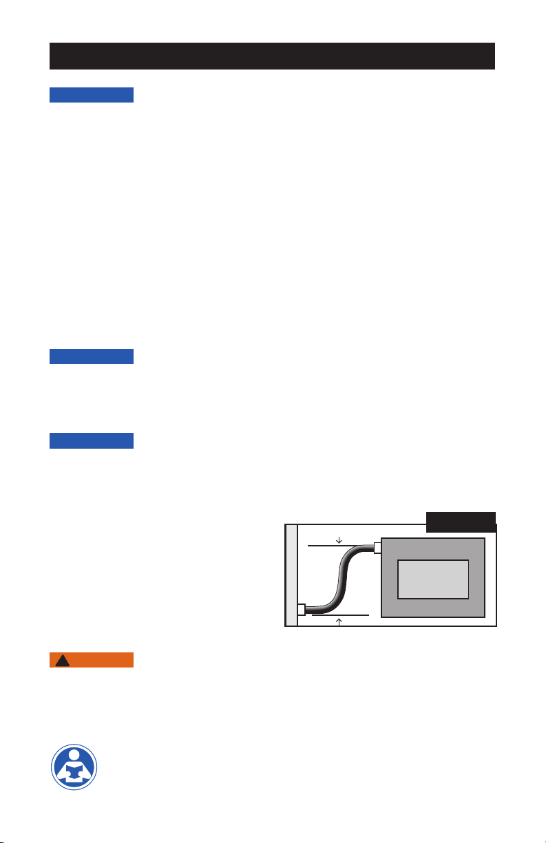
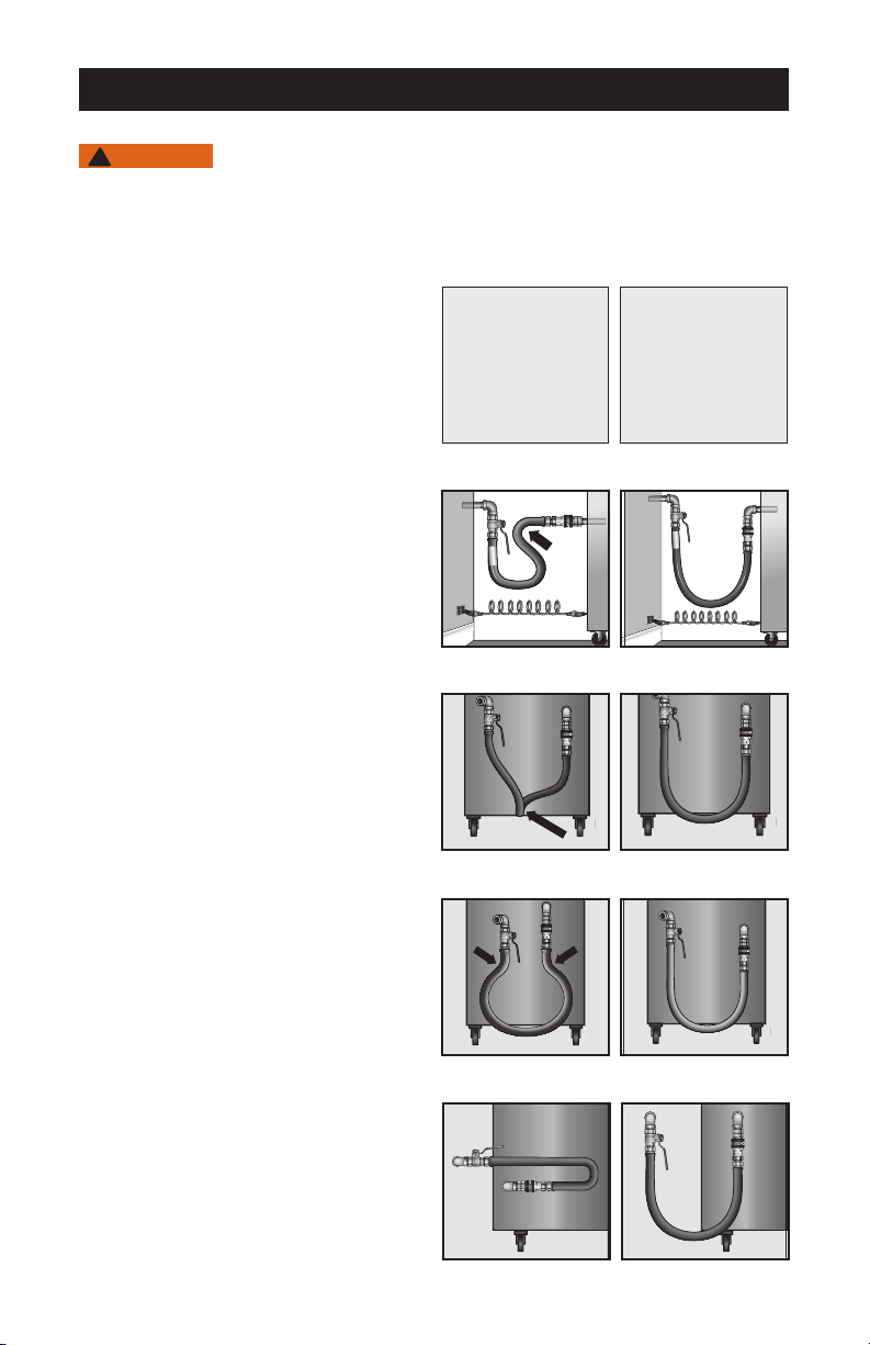
• DO NOT over-extend the gas connector assembly as this can cause dam-
age to the gas connector and/or shorten the life of the connector. Follow all
instructions on the proper movement of the appliance for cleaning, mainte-
nance, or service.
• DO NOT use the gas connector or its accessories if they are damaged in
any way. Discard any damaged items and replace with new items.
• DO NOT run a gas connector through walls, partitions or floors. The gas
connector must always be visible and accessible and should never be
concealed.
• DO NOT install a gas connector in an area where it can come into contact
with wiring, sharp edges, or surfaces that reach temperatures in excess of
230°F (110°C).
• STRONG CLEANING SOLUTIONS OR CHEMICAL SUBSTANCES
SHOULD NOT COME IN CONTACT WITH THE GAS CONNECTOR
OR ACCESSORIES. These may include acids, solvents, fluxes with zinc
chloride, or other chlorinated chemicals. If contact occurs, rinse the gas
connector and/or accessories with water and dry thoroughly with clean
cloths. If there are any signs of damage to the gas connector or accesso-
ries, turn off the gas supply and have the gas line replaced by a profession-
al immediately.
• The final assembly MUST BE tested for leaks. NEVER use an open flame
or other sources of ignition for leak testing purposes and be aware that
some leak test solutions may cause corrosion. RINSE THE INSTALLED
ASSEMBLY WITH WATER AFTER HAVING THE LEAK TEST
PERFORMED. To check the gas supply piping system for leakage, see
National Fuel Gas Code (ANSI Z223.1/NFPA 54), Natural Gas and Propane
Installation Code (B149.1), or the International Fuel Gas Code (IFGC). If an
odor of gas is detected or suspected, turn off the gas to the appliance and
have a licensed contractor identify the leak source and eliminate it.
• DO NOT use the gas connector as an appliance ground. Appliance must
be independently and properly grounded.
• NEVER jump, stand or otherwise place weight on the gas connector,
regardless of whether it is connected or disconnected.
To avoid injury, death, fire, explosion, gas leak, or property damage:

9
NOTICE
The Blue Hose gas connector system has multiple configurations for installation, all of which are
identified and discussed in this manual. The following installation configurations are possible:
• Gas Line – Manual Shut-Off Valve – Swivel MAX®– Blue Hose – SnapFast QD – Appliance
• Gas Line – Manual Shut-Off Valve – Blue Hose – Swivel MAX®– SnapFast QD – Appliance
• Gas Line – Manual Shut-Off Valve – Swivel MAX – Blue Hose – Swivel MAX – SnapFast QD
– Appliance
• Gas Line – Safety Quik®– Blue Hose – Appliance
• Gas Line – Safety Quik – Swivel MAX – Blue Hose – Appliance
• Gas Line – Safety Quik – Blue Hose – Swivel MAX – Appliance
• Gas Line – Safety Quik – Swivel MAX – Blue Hose – Swivel MAX – Appliance
• Gas Line – Manual Shut-Off Valve – SnapFast QD – Blue Hose – Appliance
• Gas Line – Manual Shut-Off Valve – SnapFast QD – Swivel MAX – Blue Hose – Appliance
• Gas Line – Manual Shut-Off Valve – SnapFast QD – Blue Hose – Swivel MAX – Appliance
• Gas Line – Manual Shut-Off Valve – SnapFast QD – Swivel MAX – Blue Hose – Swivel MAX
– Appliance
The Standard Snap QD can replace the SnapFast QD in any of the above configurations.
NOTICE
Please carefully consider your installation configuration and identify the relevant steps for
installation before you begin your installation. Be sure that the gas connector to be used is
the right length and type for the location and appliance to be served. Only one gas connector
should be used per appliance.
NOTICE
In identifying the proper configuration for your installation, consideration should be given to the
location of the connection end points for the gas supply and the appliance. Note that the loca-
tion of the gas supply and appliance connection end points can vary greatly in each
location and for each appliance. Dormont
recommends that the gas supply manifold be
located 30 to 42 inches from the floor. Any
pipe tees should be pointed in the down-
ward direction upon installation. To ensure
that the appliance can be moved as close
as possible to the wall for maximum aisle
space, the Blue Hose should be installed so
that its two ends are offset to the side from
each other (+/- 3" offset is recommended)
and parallel (never perpendicular) to both the
wall and the appliance. See Figure A.
WARNING
!
Each appliance connected with a Blue Hose gas connector MUST have its own approved
manual shutoff valve. If the appliance being connected does not yet have a manual shutoff
valve, then the gas must be shut off at the main manifold shutoff valve and an approved man-
ual shutoff valve MUST be installed. The main manifold shutoff valve also MUST be turned off
if a manual shutoff valve is being replaced or installed on the gas supply manifold.
Two 14" adjustable wrenches are recommended as installation tools.
Installation
W
A
L
L
EQUIPMENT
OFFSET
Figure A
Top-Down View

10
Installation Rights and Wrongs
WARNING
!
Upon completion, the Blue Hose gas connector MUST NOT BE kinked, twisted, or torqued,
and the end fitting of the connector MUST NOT BE subjected to sharp bends. Refer to the
following “Rights and Wrongs” to assist in your installation.
Blue Hose®Gas Connector
Installation
RIGHTS & WRONGS
SHARP BENDS: Install Blue Hose gas
connector for vertical traverse with a single,
natural loop. Avoid sharp bends that strain
and twist the connector to a point of early
failure at the coupling.
Always install the Blue Hose gas connec-
tor such that the end fittings are parallel
(never perpendicular) to both the wall and
appliance.
TWISTING: Couplings and gas connector
should be installed in the same vertical
plane. Failure to do so causes torsional
twisting and undue strain, which will cause
premature failure.
FATIGUE: Maintain the minimum or larger
bending diameter between the couplings
creates double bends causing work fatigue
at the fittings.
SELF-DRAINING: In all installations where
“self-draining” is not necessary, connect
the gas connector in a vertical loop. Do
not connect the gas connector horizontally
unless “self-draining” is necessary, in which
case support on the lower plane should
be used and the use of one or two Swivel
Max swivels is recommended.
GAS
GAS
FLOW
CM
GAS
FLOW
DORMONT
SnapFast
GAS
FLOW
CM
GAS
FLOW
DORMONT
SnapFast
GAS
FLOW
CM
GAS
FLOW
DORMONT
SnapFast
GAS
GAS
FLOW
CM
GAS
FLOW
DORMONT
SnapFast
GAS
FLOW
CM
GAS
FLOW
DORMONT
SnapFast
GAS
FLOW
CM
GAS
FLOW
DORMONT
SnapFast
Minimum pull of
equipment away from
the wall is permissible
for accessibility to the
Safety Quik®combi-
nation valve and QD
(where installed).
Avoid sharp bends
and kinks when
pulling equipment
away from the wall.
Maximum pull will
kink ends, even if
installed properly, and
reduce connector life.
GAS
FLOW
CM
GAS
FLOW
DORMONT
SnapFast
GAS
FLOW
CM
GAS
FLOW
DORMONT
SnapFast
WRONG RIGHT
WRONG RIGHT
WRONG RIGHT
WRONG RIGHT
WRONG RIGHT

11
Installation
NOTICE
The gas appliance must be disconnected prior to maximum movement. The appliance can
remain connected if there is only minimum movement.
WARNING
!
Restraining cable is mandatory for all applications involving all types of moveable gas
appliances. Refer to the installation instructions provided with the restraining cable.
All pipe threaded connections must be tightened with wrenches to create a gas tight joint.
DO NOT overtighten or undertighten the connection. The final assembly MUST BE tested
for leaks as referenced on page 8.
Installation – Option 1
Connection to Gas Supply with Manual Shutoff Valve
1. Remove the Blue Hose gas connector and all additional items, accessories, and parts
from the Dormont Blue Hose Gas Connector Kit box or bag. Ensure you have all the
necessary parts for your planned installation configuration.
WARNING
!
2. Ensure that the main manifold shutoff valve is turned off. Ensure that the appliance to be
served is shut off. If a manual shutoff valve is already installed, ensure that it is turned off
and proceed to the notice called out in the box before Step 7.
NOTICE
The shutoff valve should be located as close as possible to the gas supply manifold with
enough clearance that the valve handle can be turned on or off.
3. Ensure that the gas outlet is in the same room as the appliance and within six feet of the
appliance to be served.
4. Install a manual shutoff valve (not provided) by applying thread sealant (pipe dope) or
thread tape to the threaded ends of a three-inch long pipe nipple (not supplied).
5. Hand thread the pipe nipple into the female pipe tee on the gas supply manifold. Tighten
the connection with wrenches.
6. Hand thread the manual shutoff valve onto the other end of the pipe nipple. Tighten the
connection with wrenches.
NOTICE
Before proceeding with Step 7, your installation configuration may involve the installation of
an available accessory listed below. Refer to the appropriate page for each accessory before
proceeding.
• Swivel MAX: See Gas Supply Side Installation Instructions on page 16.
• SnapFast QD or Standard Snap QD: See instructions on page 18. NOTE that the quick
disconnect is typically installed on the appliance side due to ease of access but can be
installed on the gas supply side as well.
DO NOT PROCEED to the next step if you have installed any additional accessories that you
are using in your configuration. Refer to the instructions for that accessory on which step to
next proceed to.
7. Apply thread sealant (pipe dope) or thread tape to the male threads of one end of the
Blue Hose gas connector end fitting.
8. Hand thread the end of the Blue Hose into the gas shutoff valve. Tighten the connection
with wrenches.

12
NOTICE
Dormont strongly recommends that a SnapFast QD be installed to the appliance side of the
Blue Hose connector. An appliance-side SnapFast QD installation allows the operator to
more easily move the equipment away from the wall in an equipment line-up and to safely
disconnect the gas connector from the back of the appliance. The instructions will continue
by assuming that a SnapFast QD will be installed. If you are not using a SnapFast QD at the
appliance side, see instructions on page 18. A Standard Snap QD can be used in place of a
SnapFast QD.
WARNING
!
The SnapFast QD or Standard Snap QD MUST be oriented so that the gas enters the female
(coupling) side and exits from the male nipple. FOLLOW THE FLOW DIRECTION ARROWS
that are permanently marked on the SnapFast QD or Standard Snap QD.
9. Apply thread sealant (pipe dope) or thread tape to the male stub-out on the appliance.
Hand thread the female side of a street elbow onto the stub-out. Tighten the connection
with wrenches.
10. Apply thread sealant (pipe dope) or thread tape to the threads of the male side of the
street elbow.
11. Separate the SnapFast QD nipple from the SnapFast QD by pulling back on the sleeve
collar of the coupling end and pulling the nipple off.
12. Hand thread the female end of the SnapFast QD nipple onto the male end of the street
elbow. Tighten the connection with wrenches.
NOTICE
Before proceeding with Step 13, your installation configuration may involve the installation of
a Swivel MAX at this stage. See Appliance Side Installation Instructions with SnapFast QD on
page 16. If using a Swivel MAX at this stage of your configuration, DO NOT PROCEED to the
next step if you have installed a Swivel MAX. Refer to the instructions for that accessory on
which step to next proceed to.
13. Apply thread sealant (pipe dope) or thread tape to the threads of uninstalled end of the
Blue Hose connector.
14. Hand thread the SnapFast QD coupling end to the Blue Hose gas connector end fitting.
Tighten the connection with wrenches.
15. Reconnect the SnapFast QD nipple to the coupling end by pushing the nipple into the
coupling end with one hand. For additional instruction on how to use the SnapFast QD,
see page 21.
GAS
FLOW
CM
GAS
FLOW
DORMONT
SnapFast
Gas Flow Direction
Coupling Sleeve Nipple
Installation

13
16. Check the tightness of all connections throughout the installation. Tighten with wrenches
as needed.
17. Perform a leak test in accordance with accepted tested procedures.
18. Install a restraining cable. Refer to the separate instructions provided with the restraining
cable to install.
NOTICE
A restraining cable is required by fuel gas codes and ANSI/CSA product standards on move-
able foodservice gas equipment to prevent damage to the gas connector when moving the
appliance or cleaning or servicing the appliance. Dormont recommends use of its restraining
cable, which is included in all standard Blue Hose gas connector kits. Refer to the installation
instructions provided with the restraining cable.
19. Carefully return the gas appliance to its precise operation position. Dormont recom-
mends using Dormont’s Safety-Set to ensure that the appliance does not move during
operation and always returns to the same operating position following service or main-
tenance. Refer to the separate instructions provided with the Safety-Set to install. The
Safety-Set complies with NFPA codes 17A (5.6.4 and 96 (12.1.2.3).
20. Complete a final inspection of your installation. Refer to the Installation Rights and
Wrongs to ensure that the product is not kinked, bent, or torqued, and check to make
sure that the connector is not caught under the appliance casters.
Installation

14
Installation – Option 2
Connection to Gas Supply with Safety Quik®
NOTICE
Safety Quik should only be installed at the gas supply manifold outlet end of a gas connector
installation. DO NOT install it on the appliance end.
1. Remove the Blue Hose gas connector and all additional items, accessories, and parts
from the Dormont Blue Hose Gas Connector Kit box or bag. Ensure you have all the
necessary parts for your planned installation configuration.
WARNING
!
2. Ensure that the main manifold shutoff valve is turned off. Ensure that the appliance to be
served is shut off.
NOTICE
Safety Quik should be located as close as possible to the gas supply manifold with enough
clearance that the valve handle can be turned on or off.
WARNING
!
The Safety Quik MUST be oriented so that the gas enters the female (coupling) side and exits
from the male nipple. FOLLOW THE FLOW DIRECTION ARROWS that are permanently
marked on the Safety Quik.
3. Ensure that the gas outlet is in the same room as the appliance and within six feet of the
appliance to be served.
4. Apply thread sealant (pipe dope) or thread tape to the male threads of the drop-off pipe
from the gas supply manifold.
5. Ensure that the Safety Quik shutoff valve is in the “Off” position with the handle perpen-
dicular to the valve. For further instructions on how to operate the Safety Quik, refer to
page 21.
6. Hand thread the female shutoff valve end of the Safety Quik onto the male manifold
drop-off pipe. Tighten the connection with wrenches.
7. Separate the Safety Quik nipple from the valve by pulling back on the sleeve collar and
pulling the nipple off. The Safety Quik must be in an “Off” position to pull back on the
sleeve collar.
Diagram 1: OFF POSITION
Shut-Off Valve
Safety Sleeve Nipple
Diagram 2: ON POSITION
Coupling
Gas Flow
Installation

15
Installation
NOTICE
Before proceeding with Step 8, your installation configuration may involve the installation of a
Swivel MAX at this stage. See Gas Supply Side Installation Instructions on page 16. If using
a Swivel MAX at this stage of your configuration, DO NOT PROCEED to the next step if you
have installed a Swivel MAX. Refer to the instructions for that accessory on which step to next
proceed to.
8. Apply thread sealant (pipe dope) or thread tape to the male threads of the Blue Hose gas
connector end fitting.
9. Hand thread the Blue Hose end fitting into the threaded female section of the Safety
Quik nipple. Tighten the connection with wrenches.
10. Apply thread sealant (pipe dope) or thread tape to the male stub-out of the appliance.
11. Hand thread the female end of a street elbow onto the stub-out. Tighten with wrenches.
12. Apply thread sealant (pipe dope) or thread tape to the male end of the street elbow.
13. Hand thread a threaded Female x Female coupling (not included) to the male end of the
street elbow. Tighten the connection with wrenches.
NOTICE
Before proceeding with Step 14, your installation configuration may involve the installation of
a Swivel MAX at this stage. See Appliance Side Installation Instructions on page 17. If using
a Swivel MAX at this stage of your configuration, DO NOT PROCEED to the next step if you
have installed a Swivel MAX. Refer to the instructions for that accessory on which step to next
proceed to.
14. Apply thread sealant (pipe dope) or thread tape to the threads of the uninstalled end of
the Blue Hose gas connector.
15. Hand thread the Blue Hose gas connector end fitting into the female threaded coupling.
Tighten with wrenches.
16. Reconnect the Safety Quick by pushing the nipple into the valve section of the Safety
Quik.
17. Check the tightness of all connections throughout the installation. Tighten with wrenches
as needed.
18. Perform a leak test in accordance with accepted tested procedures.
19. Install a restraining cable. Refer to the separate instructions provided with the restraining
cable to install.
NOTICE
A restraining cable is required by fuel gas codes and ANSI/CSA product standards on move-
able foodservice gas equipment to prevent damage to the gas connector when moving the
appliance or cleaning or servicing the appliance. Dormont recommends use of its restraining
cable, which is included in all standard Blue Hose gas connector kits. Refer to the installation
instructions provided with the restraining cable.
20. Carefully return the gas appliance to its precise operation position. Dormont recom-
mends using Dormont’s Safety-Set to ensure that the appliance does not move during
operation and always returns to the same operating position following service or main-
tenance. Refer to the separate instructions provided with the Safety-Set to install. The
Safety-Set complies with NFPA codes 17A (5.6.4 and 96 (12.1.2.3).
21. Complete a final inspection of your installation. Refer to the Installation Rights and
Wrongs to ensure that the product is not kinked, bent, or torqued, and check to make
sure that the connector is not caught under the appliance casters.

16
Installation
Installation -– Swivel MAX®
WARNING
!
• Swivel MAX can ONLY be used in piping with fuel gas pressures that DO NOT exceed 1/2
PSIG.
• ONLY use thread sealant (pipe dope) on the Swivel MAX fitting. DO NOT USE thread tape
on the joint between the Blue Hose male threads and the Swivel MAX female threads.
• DO NOT overtighten the Swivel MAX connections.
NOTICE
Ensure that the Swivel MAX is always visible and never installed within walls, floors or parti-
tions. The Swivel MAX can be installed after the manual shutoff valve, Safety Quik, SnapFast
QD, or Standard Snap QD and before the Blue Hose on the gas supply side or after the Blue
Hose and before the SnapFast QD or Standard Snap QD on the appliance side.
NOTICE
If you are installing a Swivel MAX on both the gas supply side and the appliance side, install
the Swivel MAX on the gas supply side first and appliance side second.
Gas Supply Side Installation (Manual Shutoff Valve or Safety Quik)
1. Apply thread sealant (pipe dope) to the threads of one end of a Blue Hose gas connector.
2. Hand thread the gas connector end into the female side of the Swivel MAX.
3. Apply thread sealant (pipe dope) to the threads of the male end of the Swivel MAX.
4. Hand thread the male end of the Swivel MAX into the female threads of the gas shutoff
valve, the Safety Quik nipple, the SnapFast QD, or the Standard Snap QD depending on
you installation configuration.
5. Carefully tighten the connection with wrenches.
6. Proceed to Option 1, Step 10 if Swivel MAX was connected to the gas shutoff valve.
Proceed to Option 2, Step 10 if the Swivel MAX was connected to a Safety Quik. Proceed
to Installation – SnapFast QD or Standard Snap QD on Gas Supply Side, Step 8 if the
Swivel MAX was connected to a SnapFast QD or Standard Snap QD.
Appliance Side Installation with a SnapFast QD or Standard Snap QD
1. Apply thread sealant (pipe dope) to the threads of appliance end of the Blue Hose gas con-
nector.
2. Hand thread the Blue Hose gas connector end into the female end of the Swivel MAX.
3. Apply thread sealant (pipe dope) to the threads of the male end of the Swivel MAX.
4. Hand thread the male end of the Swivel MAX into the female coupling end of the SnapFast
QD.
5. Carefully tighten both connections with wrenches.
6. Proceed to Option 1, Step 15.

17
Installation
Appliance Side Installation
1. Apply thread sealant (pipe dope) to the threads of the uninstalled end of the Blue Hose gas
connector.
2. Hand thread the Blue Hose gas connector end into the female end of the Swivel MAX.
3. Apply thread sealant (pipe dope) to the male threaded end of the Swivel MAX.
4. Hand thread the threaded male end of the Swivel MAX into the Female x Female coupling.
5. Carefully tighten both connections with wrenches.
6. Proceed to Option 2, Step 16.

18
Installation
NOTICE
Never insert objects such as screwdrivers and probes into the SnapFast QD or Standard Snap
QD, as the QD seat can be damaged or forced off center.
Installation – SnapFast QD or Standard Snap QD on Gas
Supply Side
WARNING
!
• The SnapFast QD and Standard Snap QD MUST be oriented so that the gas enters the
female (coupling) side and exits from the male nipple. FOLLOW THE FLOW DIRECTION
ARROWS that are permanently marked on the SnapFast QD and Standard Snap QD.
• DO NOT USE the SnapFast QD and Standard Snap QD with a dual-fed manifold gas inlet.
Such an installation is dangerous and may result in injury, death, fire, explosion, gas leak,
or property damage. In this situation, a Blue Hose gas connector may be used without a
SnapFast QD and Standard Snap QD.
1. Apply thread sealant (pipe dope) or thread tape to one end of a Male x Male pipe nipple
(not included).
2. Hand thread the pipe nipple onto the gas shutoff valve outlet. Tighten the connection
with wrenches.
3. Apply thread sealant (pipe dope) or thread tape to the opposite end of the Male x Male
pipe nipple.
4. Separate the SnapFast QD or Standard Snap QD nipple from the SnapFast QD or
Standard Snap QD by pulling back on the sleeve collar of the coupling end and pulling
the nipple off.
5. Hand thread the SnapFast QD or Standard Snap QD coupling end to the Male x Male
pipe nipple. Tighten the connection with wrenches.
NOTICE
Before proceeding with Step 6, your installation configuration may involve the installation of a
Swivel MAX at this stage. See Gas Supply Side Installation Instructions on page 16. If using
a Swivel MAX at this stage of your configuration, DO NOT PROCEED to the next step if you
have installed a Swivel MAX. Refer to the instructions for that accessory on which step to next
proceed to.
6. Apply thread sealant (pipe dope) or thread tape to the male threads of one end of the
Blue Hose gas connector.
7. Hand thread the Blue Hose gas connector end into the SnapFast QD or Standard Snap
QD male nipple. Tighten the connection with wrenches.
8. Apply thread sealant (pipe dope) or thread tape to the male stub-out of the appliance.
9. Hand thread the female end of a street elbow onto the stub-out. Tighten with wrenches.
10. Apply thread sealant (pipe dope) or thread tape to the male end of the street elbow.
11. Hand thread a threaded Female x Female coupling (not included) to the male end of the
street elbow. Tighten the connection with wrenches

19
Installation
NOTICE
Before proceeding with Step 12, your installation configuration may involve the installation of
a Swivel MAX at this stage. See Appliance Side Installation Instructions on page 17. If using
a Swivel MAX at this stage of your configuration, DO NOT PROCEED to the next step if you
have installed a Swivel MAX. Refer to the instructions for that accessory on which step to next
proceed to.
12. Apply thread sealant (pipe dope) or thread tape to the uninstalled end of the Blue Hose
gas connector.
13. Hand thread the Blue Hose gas connector end fitting into the female threaded coupling.
Tighten with wrenches.
14. Reconnect the SnapFast QD or Standard Snap QD nipple to the coupling end by push-
ing the nipple into the coupling end with one hand. For additional instruction on how to
use the SnapFast QD or Standard Snap QD, see page 21.
15. Check the tightness of all connections throughout the installation. Tighten with wrenches
as needed.
16. Perform a leak test in accordance with accepted tested procedures.
17. Install a restraining cable. Refer to the separate instructions provided with the restraining
cable to install.
18. Carefully return the gas appliance to its precise operation position. Dormont recom-
mends using Dormont’s Safety-Set to ensure that the appliance does not move during
operation and always returns to the same operating position following service or main-
tenance. Refer to the separate instructions provided with the Safety-Set to install. The
Safety-Set complies with NFPA codes 17A (5.6.4 and 96 (12.1.2.3).
19. Complete a final inspection of your installation. Refer to the Installation Rights and
Wrongs to ensure that the product is not kinked, bent, or torqued, and check to make
sure that the connector is not caught under the appliance casters.

20
Installation
GAS
FLOW
CM
GAS
FLOW
DORMONT
SnapFast
Gas Flow Direction
Coupling Sleeve Nipple
SnapFast QD and Standard Snap QD Operating Instructions
WARNING
!
• SnapFast QD and Standard Snap QD ARE NOT to be used as the primary gas shutoff.
Unless upstream gas shutoff valves are completely closed, disconnecting the SnapFast QD
or Standard Snap QD will result in open gas flow.
• DO NOT drop the SnapFast QD or Standard Snap QD coupling on the floor as it may
cause damage to the SnapFast QD or Standard Snap QD.
• NEVER insert foreign objects such as screwdrivers or probes into the SnapFast QD or
Standard Snap QD.
TO CONNECT: Push the SnapFast QD nipple into the coupling body until the coupling sleeve
snaps forward against the retaining ring. For the Standard Snap QD you must retract the
sleeve with one hand to engage the nipple into the coupling body.
TO DISCONNECT: Close the shutoff valve to turn off the gas. Retract the coupling sleeve by
pulling it away from the nipple with one hand. This will disconnect the coupling body from the
nipple.
This manual suits for next models
1
Table of contents
Languages: