Dorner Mfg. Corp. 6 851-717 Rev. A
2200 and 2300 Series Center Mount Drive Package for SEW 60 Hz Gearmotors
Specifications
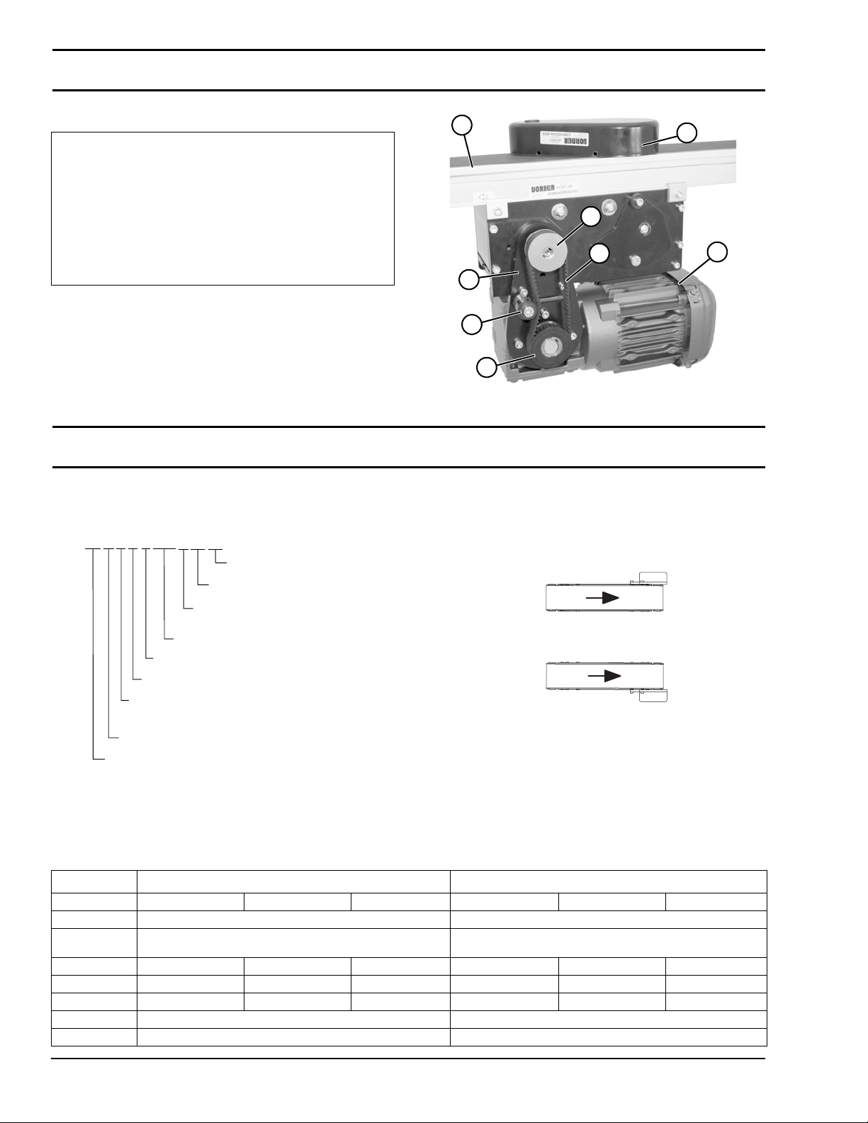
Table 3: Belt Speeds for Variable Speed SEW Gearmotors
Part Number RPM In-lb N-m Ft/min (max) Ft/min (min) M/min (max) M/min (min) Drive
Pulley
Driven
Pulley
22M039WS423EN 46 203 22.9 9.6 1.6 2.9 0.5 19 32
22M039WS423EN 46 203 22.9 11.0 1.8 3.4 0.6 19 28
22M039WS423EN 46 203 22.9 11.1 1.9 3.4 0.6 22 32
22M039WS423EN 46 203 22.9 12.7 2.1 3.9 0.6 22 28
22M039WS423EN 46 203 22.9 14.2 2.4 4.3 0.7 28 32
22M039WS423EN 46 203 22.9 16.2 2.7 4.9 0.8 32 32
22M039WS423EN 46 203 22.9 18.5 3.1 5.6 0.9 32 28
22M039WS423EN 46 203 22.9 20.6 3.4 6.3 1.0 28 22
22M039WS423EN 46 203 22.9 22.3 3.7 6.8 1.1 44 32
22M017WS423EN 109 159 18.0 22.7 3.8 6.9 1.2 19 32
22M039WS423EN 46 203 22.9 23.6 3.9 7.2 1.2 32 22
22M039WS423EN 46 203 22.9 23.9 4.0 7.3 1.2 28 19
22M039WS423EN 46 203 22.9 24.3 4.1 7.4 1.2 48 32
22M039WS423EN 46 203 22.9 25.5 4.2 7.8 1.3 44 28
22M017WS423EN 109 159 18.0 25.9 4.3 7.9 1.3 19 28
22M017WS423EN 109 159 18.0 26.3 4.4 8.0 1.3 22 32
22M039WS423EN 46 203 22.9 27.3 4.5 8.3 1.4 32 19
22M039WS423EN 46 203 22.9 27.8 4.6 8.5 1.4 48 28
22M017WS423EN 109 159 18.0 30.0 5.0 9.2 1.5 22 28
22M039WS423EN 46 203 22.9 32.4 5.4 9.9 1.6 44 22
22M017WS423EN 109 159 18.0 33.4 5.6 10.2 1.7 28 32
22M039WS423EN 46 203 22.9 35.4 5.9 10.8 1.8 48 22
22M039WS423EN 46 203 22.9 37.5 6.3 11.4 1.9 44 19
22M017WS423EN 109 159 18.0 38.2 6.4 11.6 1.9 32 32
22M039WS423EN 46 203 22.9 40.9 6.8 12.5 2.1 48 19
22M017WS423EN 109 159 18.0 43.7 7.3 13.3 2.2 32 28
22M008WS423EN 219 132 14.9 45.6 7.6 13.9 2.3 19 32
22M017WS423EN 109 159 18.0 48.6 8.1 14.8 2.5 28 22
22M008WS423EN 219 132 14.9 52.1 8.7 15.9 2.6 19 28
22M017WS423EN 109 159 18.0 52.5 8.8 16.0 2.7 44 32
22M008WS423EN 219 132 14.9 52.8 8.8 16.1 2.7 22 32
22M017WS423EN 109 159 18.0 55.6 9.3 16.9 2.8 32 22
22M017WS423EN 109 159 18.0 56.3 9.4 17.2 2.9 28 19
22M017WS423EN 109 159 18.0 57.3 9.6 17.5 2.9 48 32
22M017WS423EN 109 159 18.0 60.0 10.0 18.3 3.1 44 28
22M008WS423EN 219 132 14.9 60.3 10.1 18.4 3.1 22 28
22M017WS423EN 109 159 18.0 64.4 10.7 19.6 3.3 32 19
22M017WS423EN 109 159 18.0 65.5 10.9 20.0 3.3 48 28
22M008WS423EN 219 132 14.9 67.2 11.2 20.5 3.4 28 32
22M017WS423EN 109 159 18.0 76.4 12.7 23.3 3.9 44 22
22M008WS423EN 219 132 14.9 76.8 12.8 23.4 3.9 32 32
22M017WS423EN 109 159 18.0 83.4 13.9 25.4 4.2 48 22
22M008WS423EN 219 132 14.9 87.8 14.6 26.8 4.5 32 28
22M017WS423EN 109 159 18.0 88.5 14.7 27.0 4.5 44 19
22M017WS423EN 109 159 18.0 96.5 16.1 29.4 4.9 48 19
22M008WS423EN 219 132 14.9 97.7 16.3 29.8 5.0 28 22
22M008WS423EN 219 132 14.9 105.6 17.6 32.2 5.4 44 32
22M008WS423EN 219 132 14.9 111.7 18.6 34.1 5.7 32 22
22M008WS423EN 219 132 14.9 113.2 18.9 34.5 5.7 28 19
22M008WS423EN 219 132 14.9 115.2 19.2 35.1 5.9 48 32
22M008WS423EN 219 132 14.9 120.7 20.1 36.8 6.1 44 28
22M008WS423EN 219 132 14.9 129.4 21.6 39.4 6.6 32 19
22M008WS423EN 219 132 14.9 131.7 21.9 40.1 6.7 48 28
22M008WS423EN 219 132 14.9 153.6 25.6 46.8 7.8 44 22
22M008WS423EN 219 132 14.9 167.6 27.9 51.1 8.5 48 22
22M008WS423EN 219 132 14.9 177.9 29.6 54.2 9.0 44 19
22M008WS423EN 219 132 14.9 194.0 32.3 59.1 9.9 48 19
NOTE
For belt speed other than those listed, contact
factory for details.