Dorner 62M050PLBDDEN User manual

For other service manuals visit our website at:
www.dorner.com/service_manuals.asp
DORNER MFG. CORP. INSIDE THE USA OUTSIDE THE USA
P.O. Box 20 • 975 Cottonwood Ave. TEL: 1-800-397-8664 TEL: 262-367-7600
Hartland, WI 53029-0020 USA FAX: 1-800-369-2440 FAX: 262-367-5827
851-738 Rev. A
Brushless DC Motor Control
Installation, Maintenance and Parts Manual

Dorner Mfg. Corp. 2 851-738 Rev. A
Brushless DC Motor Control
Table of Contents
Introduction ......................................................................... 2
Warnings -General Safety ................................................. 3
Product Description ............................................................. 4
Brushless DC Motor Control ........................................... 4
Specifications ...................................................................... 5
2200 Light Load Gearmotors........................................... 5
2200 and 3200 Standard Load Gearmotors ..................... 5
2200 Standard Load 90° Gearmotors............................... 5
Controllers ....................................................................... 5
Installation ........................................................................... 6
Required Tools................................................................. 6
Conveyor Mounting ......................................................... 6
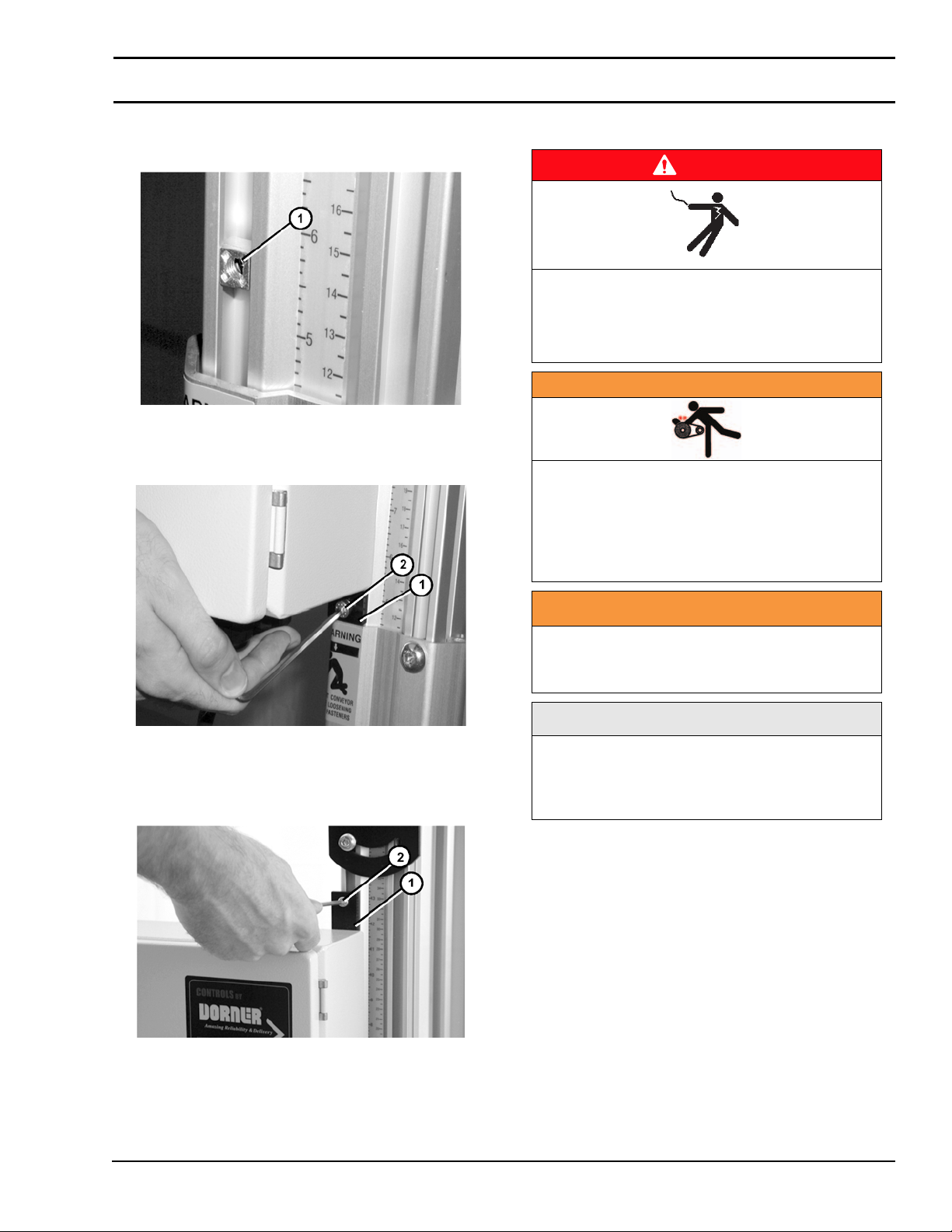
Stand Mounting................................................................ 7
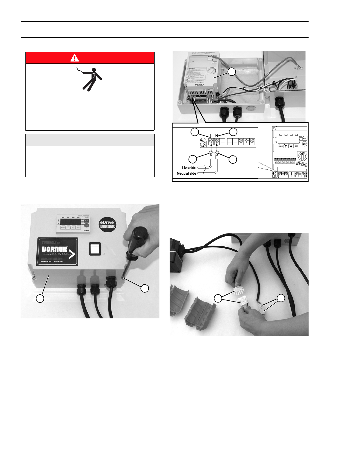
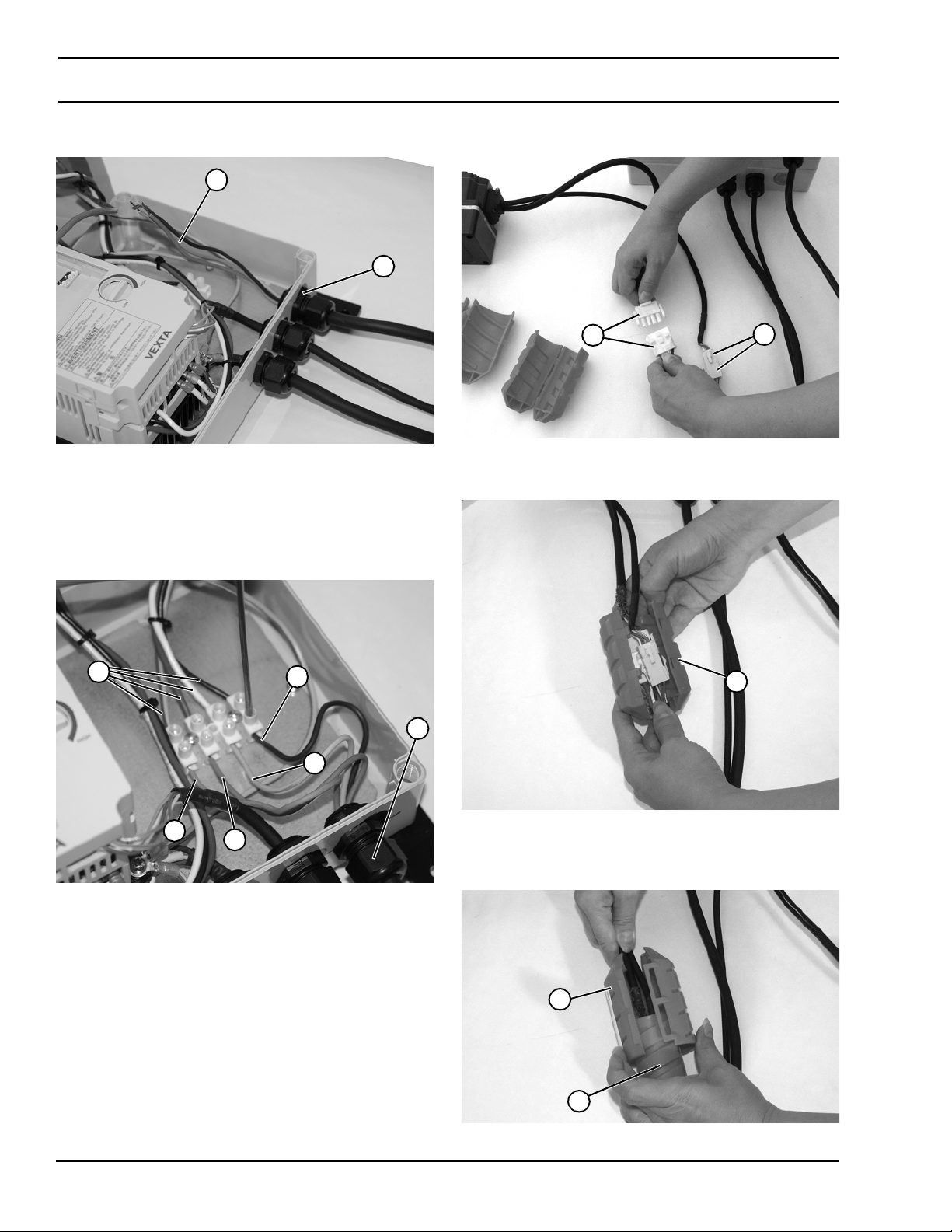
Wiring .............................................................................. 7
For 1 Phase (115 Volt) Controllers: ............................. 8
For 3 Phase (230 Volt) Controllers: ............................. 9
For Remote ON/OFF Signal: ...................................... 11
External Input Signals................................................. 12
Input Signal Connection Terminals ........................ 12
Operation............................................................................ 13
Controller Setup ............................................................ 13
Setting Speed Acceleration and Deceleration............. 13
Set Motor Direction .................................................... 15
Displaying the Conveyor Belt Speed.......................... 15
Setting Speed While Motor is Running ...................... 17
Switching the Signal Method
to Remote Signal (If Required)................................... 17
Notes .................................................................................. 18
Service Parts....................................................................... 19
Brushless DC Motor Control.......................................... 19
Return Policy...................................................................... 20
Introduction
Upon receipt of shipment:
• Compare shipment with packing slip. Contact factory
regarding discrepancies.
• Inspect packages for shipping damage. Contact carrier
regarding damage.
• Accessories may be shipped loose. See accessory instruc-
tions for installation.
The Dorner Limited Warranty applies.
Dorner reserves the right to make changes at any time
without notice or obligation.
Dorner has convenient, pre-configured kits of Key Service
Parts for all conveyor products. These time saving kits are
easy to order, designed for fast installation, and guarantee
you will have what you need when you need it. Key Parts
and Kits are marked in the Service Parts section of this
manual with the Performance Parts Kits logo .
A
CAUTION
Some illustrations may show guards
removed. DO NOT operate equipment without
guards.

851-738 Rev. A 3 Dorner Mfg. Corp.
Brushless DC Motor Control
Warnings -General Safety
WARNING
The safety alert symbol, black triangle with
white exclamation, is used to alert you to
potential personal injury hazards.
DANGER
SEVERE HAZARD!
KEEP OFF CONVEYORS. Climbing, sitting,
walking or riding on conveyor will cause
severe injury.
DANGER
EXPLOSION HAZARD!
• DO NOT OPERATE CONVEYORS IN AN
EXPLOSIVE ENVIRONMENT. The electric
gearmotor generates heat and could ignite
combustible vapors.
• Failure to comply will result in death or
serious injury.
WARNING
Controller must be properly grounded.
Failure to properly ground controller may
cause injury to personnel.
DANGER
SEVERE HAZARD!
Hazardous voltage will cause severe injury
or death. LOCKOUT POWER BEFORE
WIRING.
WARNING
SEVERE HAZARD!
Exposed moving parts can cause severe
injury. DO NOT ATTEMPT ADJUSTMENTS
WITH CONVEYOR RUNNING. LOCK OUT
POWER before removing guards or
performing maintenance.
WARNING
SEVERE HAZARD!
• Dorner cannot control the physical
installation and application of conveyors.
Taking protective measures is the
responsibility of the user.
• When conveyors are used in conjunction
with other equipment or as part of a
multiple conveyor system, CHECK FOR
POTENTIAL PINCH POINTS and other
mechanical hazards before system start-
up.
• Failure to comply could result in serious
injury.
A
A
A
A

Dorner Mfg. Corp. 4 851-738 Rev. A
Brushless DC Motor Control
Product Description
Brushless DC Motor Control
Dorner’s Brushless DC Motor Control (Figure 1) are DC
motor speed controllers for Standard and Heavy Load VFD
gearmotors.
Figure 1
Figure 1
Typical Components
1 Mode indicator LEDs
The illuminating LED indicates the current operation
mode.
• MNTR: Monitor mode
• F/R: Direction setting mode
• LO/RE: Digital operator/external input signal set-
ting mode
• PRGM: Data setting mode
2 Unit display LEDs
The illuminating LED indicates the current display
unit.
• r/min: Speed of motor or gearhead output shaft
• m/min: Conveyor transfer speed
• %: Load factor
3 RUN = Start the motor operation.
4 STOP = Stop the motor.
5 ON/OFF Power Switch.
6 Use these keys to switch the mode or set data.
• Switch the operation mode
• Move to the next item or increase the value
• Move to the previous item or decrease the value
• Confirm the data
7Display
8 ALARM LED: A red light will come on when an
alarm is generated.
9 RUN LED: A green light stays on during operation.
NOTE
For additional information, refer to the
Oriental Motor Operating Manual shipped
with your controller. See Specifications table
for models.
1
3
4
5
6
8
9
2
7

851-738 Rev. A 5 Dorner Mfg. Corp.
Brushless DC Motor Control
Specifications
2200 Light Load Gearmotors
2200 and 3200 Standard Load Gearmotors
2200 Standard Load 90° Gearmotors
Controllers
Dorner Model
Number Max RPM* Type HP Kw FLA In-lbs N-m
62M050PLBDDEN 60 A 0.083 0.060 See Control 76 8.6
62M020PLBDDEN 150 A 0.083 0.060 See Control 31 3.6
62M015PLBDDEN 200 A 0.083 0.060 See Control 23 2.7
Dorner Model
Number Max RPM* Type HP Kw FLA In-lbs N-m
62M050PSBDDEN 60 B 0.25 0.200 See Control 240 28
62M020PSBDDEN 150 B 0.25 0.200 See Control 103 11.7
62M015PSBDDEN 300 B 0.25 0.200 See Control 52 5.9
Dorner Model
Number Max RPM* Type HP Kw FLA In-lbs N-m
62M060ESBDDEN 50 B 0.25 0.200 See Control 106 12.4
62M040ESBDDEN 75 B 0.25 0.200 See Control 123 14.3
62M020ESBDDEN 150 B 0.25 0.200 See Control 89 10.4
62M010ESBDDEN 300 B 0.25 0.200 See Control 49 5.7
62M005ESBDDEN 600 B 0.25 0.200 See Control 25 2.9
Dorner Model
Number Input Volt Input
Phase
Input
Hz
Max
Input
Amps
Output Max
Watts Reversing Type
63MBD11B60 115 1 60 4.5 BDC 60 Yes A
63MBD23B60 230 3 60 1.5 BDC 60 Yes A
63MBD11B200 115 1 60 8.8 BDC 200 Yes B
63MBD23B200 230 3 60 3.4 BDC 200 Yes B

Dorner Mfg. Corp. 6 851-738 Rev. A
Brushless DC Motor Control
Installation
Required Tools
• 6 mm hex head wrench
• Flat-blade screwdriver
• Phillips screwdriver
Installation Component List (Figure 2):
Figure 2
Figure 2
Conveyor Mounting
1. Install spring t-nuts (Figure 3, item 1) into conveyor t-
slot.
Figure 3
Figure 3
2. Attach controller (Figure 4, item 1) to conveyor with
screws (Figure 4, item 2).
Figure 4
Figure 4
3. Slide controller to its desired mounting location along
conveyor and tighten both screws.
1 Controller Mounting Bar (2x)
2 Brushless DC Controller
3 Motor Power Cord
4 External Signal Cord
5 Power Supply Cord
6 Hex Head Screws, M4 x 16 mm (4x)
7T-Bar
8 Hex Head Screws, M6 x 16 mm (2x)
12
8
7
3
4
5
6
1
2

851-738 Rev. A 7 Dorner Mfg. Corp.
Brushless DC Motor Control
Installation
Stand Mounting
1. Install spring t-nuts (Figure 5, item 1) into stand t-slot.
Figure 5
Figure 5
2. Partially thread controller mounting bar (Figure
6, item 1) to lower t-nut with screw (Figure 6, item 2).
Figure 6
Figure 6
3. Install second spring t-nut into stand t-slot.
4. Partially thread controller mounting bar (Figure
7, item 1) to top t-nut with screw (Figure 7, item 2).
Figure 7
Figure 7
5. Slide controller to its desired mounting location and
tighten both screws.
Wiring
DANGER
SEVERE HAZARD!
Hazardous voltage will cause severe injury
or death. LOCKOUT POWER BEFORE
WIRING.
WARNING
SEVERE HAZARD!
Exposed moving parts can cause severe
injury. DO NOT ATTEMPT ADJUSTMENTS
WITH CONVEYOR RUNNING. LOCK OUT
POWER before removing guards or
performing maintenance.
WARNING
Controller must be properly grounded.
Failure to properly ground control box may
cause injury to personnel.
NOTE
For additional specific wiring information and
schematics, refer to the Oriental Motor
Operating Manual shipped with your
controller.
A
A

Dorner Mfg. Corp. 8 851-738 Rev. A
Brushless DC Motor Control
Installation
For 1 Phase (115 Volt) Controllers:
1. Open controller by loosening four plastic cover screws
(Figure 8, item 1), and removing controller case cover
(Figure 8, item 2).
Figure 8
Figure 8
2. Remove controller cover (Figure 9, item 1).
Figure 9
Figure 9
3. Connect black (live side) (Figure 9, item 2) to L
(Figure 9, item 3) and white (neutral side) (Figure
9, item 4) to N (Figure 9, item 5) wires on controller.
4. Connect motor plugs (Figure 10, item 1) and (Figure
10, item 2).
Figure 10
Figure 10
DANGER
SEVERE HAZARD!
Hazardous voltage will cause severe injury
or death. LOCKOUT POWER BEFORE
WIRING.
NOTE
For 115V controllers no wiring is required.
Controller is provided with power cord. The
steps 1-3 are shown for reference, only if re-
wiring is required.
1
2
3
2
5
4
1
2
1

851-738 Rev. A 9 Dorner Mfg. Corp.
Brushless DC Motor Control
Installation
5. Install inner cord cover (Figure 11, item 1).
Figure 11
Figure 11
6. Install outer cord cover (Figure 12, item 1) over inner
cord cover (Figure 12, item 2).
Figure 12
Figure 12
7. Twist covers (Figure 13, item 1) together, as shown.
Figure 13
Figure 13
For 3 Phase (230 Volt) Controllers:
1. Open controller by loosening four plastic cover screws
(Figure 14, item 1), and removing controller case cover
(Figure 14, item 2).
Figure 14
Figure 14
1
2
1
1
DANGER
SEVERE HAZARD!
Hazardous voltage will cause severe injury
or death. LOCKOUT POWER BEFORE
WIRING.
1
2

Dorner Mfg. Corp. 10 851-738 Rev. A
Brushless DC Motor Control
Installation
2. Install four wires (Figure 15, item 1) through cord grip
opening (Figure 15, item 2) in controller assembly.
Figure 15
Figure 15
3. Connect black (Figure 16, item 1), white (Figure
16, item 2), red (Figure 16, item 3), and green (Figure
16, item 4) wires to mating color wires (Figure
16, item 5) on opposite end of wiring connector
terminals.
Figure 16
Figure 16
4. Secure wires by tightening grip (Figure 16, item 6).
5. Install case cover (Figure 14, item 2). with four plastic
cover screws (Figure 14, item 1).
6. Connect motor plugs (Figure 17, item 1) and (Figure
17, item 2).
Figure 17
Figure 17
7. Install inner cord cover (Figure 18, item 1).
Figure 18
Figure 18
8. Install outer cord cover (Figure 19, item 1) over inner
cord cover (Figure 19, item 2).
Figure 19
Figure 19
1
2
1
2
3
4
5
6
2
1
1
2
1

851-738 Rev. A 11 Dorner Mfg. Corp.
Brushless DC Motor Control
Installation
9. Twist covers (Figure 20, item 1) together, as shown.
Figure 20
Figure 20
For Remote ON/OFF Signal:
1. Remove access plug (Figure 21, item 1).
Figure 21
Figure 21
2. Open controller by loosening four plastic cover screws
(Figure 21, item 2), and removing controller case cover
(Figure 21, item 3).
3. Remove controller cover (Figure 22, item 1).
Figure 22
Figure 22
4. Install cord grip, not provided (Figure 22, item 2).
5. Insert external signal wires to terminals (Figure
22, item 3). See “External Input Signals” on page 12.
6. Be sure to configure controller for remote signals. (See
“Switching the Signal Method to Remote Signal (If
Required)” on page 17 for details.)
DANGER
SEVERE HAZARD!
Hazardous voltage will cause severe injury
or death. LOCKOUT POWER BEFORE
WIRING.
1
2
31
1
1
2
3

Dorner Mfg. Corp. 12 851-738 Rev. A
Brushless DC Motor Control
Installation
External Input Signals
External input signals must be set in accordance with the desired application.
Perform the various settings specified below using the digital operator.
Input Signal Connection Terminals
Connect the input signals according to the operation method of your system. Dry contact signals are recommended. For solid
state signals see Oriental Manual for details.
Figure 23
Figure 23
Application Necessary settings
Use input signals connected to terminals
X1, X2 and X3
Switch the operation-signal input method to “external input signals” on the
digital operator. See “Switching the Signal Method to Remote Signal (If Required)”
on page 17.
Terminal
Position
Terminal
Name Signal Name Description Necessary settings
Lower
Stage
C0 IN-COM0 Input signal common Remove the short bar and connect an
external control equipment.
C1 IN-COM0 Input signal common -
X1 CW input Clockwise rotation Set the operation-signal input method to
“external input signals” on the digital
operator.
X2 CCW input Counterclockwise rotation
TH TH M0 M1 M2 VH VM VL Y1 Y2
X0
Upper stage
Lower stage C0 C1 X1 X2 X3 X4 X5 Y0 C2
Input signal common
ON: Clockwise rotation
OFF: Stop ON: Counterclockwise rotation
OFF: Stop
Jumper X3 to Common
C3
Input signal
common (0 V)

851-738 Rev. A 13 Dorner Mfg. Corp.
Brushless DC Motor Control
Operation
Controller Setup
When purchased with a gearmotor, Dorner configures
Variable Speed VFD Controllers as follows:
• Acceleration and Deceleration, 0.5 sec
• Direction = Forward
• Speed = 0 rpm
• Remote Signal = Local (Lo)
Proceed with the following steps to change these
configurations:
Setting Speed Acceleration and
Deceleration
1. Press MODE to switch to the data setting mode. The
PRGM LED (Figure 24, item 1) will illuminate and
“SPd” (Figure 24, item 2) will be displayed.
Figure 24
Figure 24
2. Press SET (Figure 25, item 1). “P. no1” (Figure
25, item 2) will be displayed.
Figure 25
Figure 25
3. Press SET (Figure 25, item 1). Press up or down
(Figure 25, item 3) until “SPd1” (Figure 26, item 1) is
displayed. Press set (Figure 26, item 2) again. “SPd1”
(Figure 26, item 1) will blink and correct speed (Figure
26, item 3) will be displayed.
Figure 26
Figure 26
DANGER
SEVERE HAZARD!
Hazardous voltage will cause severe injury
or death. LOCKOUT POWER BEFORE
WIRING.
WARNING
SEVERE HAZARD!
Exposed moving parts can cause severe
injury. DO NOT ATTEMPT ADJUSTMENTS
WITH CONVEYOR RUNNING. LOCK OUT
POWER before removing guards or
performing maintenance.
NOTE
For additional information or desired settings
other than listed, refer to information provided
by controller manufacturer.
NOTE
The controller is capable of storing several
speed configurations of speed programs. The
following instructions are for programming
one only. For further details, see the controller
manual.
PRGM
2
1
1
2
3
1 second
later
1
2
3
A

Dorner Mfg. Corp. 14 851-738 Rev. A
Brushless DC Motor Control
Operation
4. Press up or down (Figure 27, item 1) to change the
speed (e.g., 1000 r/min) (Figure 27, item 2). Pressing
and holding the key for 3 seconds or more will increase
or decrease the value successively.
Figure 27
Figure 27
5. After the speed has been changed, press SET (Figure
28, item 1) to confirm the new setting. The display will
blink and show “Acc1” (Figure 28, item 2), after which
the acceleration time (Figure 28, item 3) will be
displayed
Figure 28
Figure 28
6. Press up or down (Figure 29, item 1) to change the
acceleration time (e.g., 5.0) (Figure 29, item 2).
Pressing and holding the key for 3 seconds or more will
increase or decrease the value successively
Figure 29
Figure 29
7. After the acceleration time has been changed, press SET
(Figure 30, item 1) to confirm the new setting. The
display will blink and show “dEc1”(Figure 30, item 2),
after which the deceleration time (Figure 30, item 3)
will be displayed.
Figure 30
Figure 30
8. Press up or down (Figure 31, item 1) to change the
deceleration time (e.g., 5.0) (Figure 31, item 2).
Pressing and holding the key for 3 seconds or more will
increase or decrease the value successively.
Figure 31
Figure 31
9. After the deceleration time has been changed, press SET
(Figure 32, item 1) to confirm the new setting. The
display will blink.
Figure 32
Figure 32
10. Press MODE to switch to the monitor mode.
NOTE
Minimum Speed = 100 rpm
Maximum Speed = 3000 rpm
1
2
1 second
later
1
2
3
1
2
1 second
later
1
2
3
1
2
1

851-738 Rev. A 15 Dorner Mfg. Corp.
Brushless DC Motor Control
Operation
Set Motor Direction
The initial setting is “For” (clockwise).
1. Press MODE to switch to the direction setting mode.
The F/R LED (Figure 33, item 1) will illuminate.
Figure 33
Figure 33
2. Press up or down (Figure 33, item 2) to select a desired
direction. “For” (Figure 33, item 3): Clockwise or
“rEv”: Counterclockwise.
3. Press SET (Figure 33, item 4) to confirm the selection.
The display will blink.
Displaying the Conveyor Belt Speed
While the motor is operating, the speed of the motor output
shaft is displayed on the digital operator. To show the speed
of the conveyor belt (speed ft/minute), set the gear ratio to
the conveyor gear ratio in use.
1. Calculate the conveyor gear ratio using the formula
below:
• Conveyor gear ratio =
•where:
• Gearhead ratio = ratio of inline or 90 degree gearbox
• Pulley diameter = Diameter of Drive Pulley (Ft)
- 2200 Series = 0.104
- 3200 Series = 0.25
- 2200 Precision Move End Drive Series = 0.125
- 2200 Precision Move Mid Drive Series = 0.167
- 3200 Precision Move End Drive Series = 0.275
- 2200 Modular Belt Series = 0.125
- 5300 Modular Belt Series = 0.325
- 5200 Modular Belt Series = 0.325
• Drive Sprocket Teeth = Number of teeth on sprocket
connected to gearmotor. Note: For all side drives = 1.
• Driven Sprocket Teeth = Number of teeth on sprocket
connected to conveyor shaft. Note: For all side drives = 1.
•Example:
- 2200 Series Conveyor with a 62M015PLBDDEN Gear-
motor and a light load bottom mount with a 44 tooth
pulley on the gearmotor and a 22 tooth pulley on the
conveyor.
• Conveyor gear ratio =
• Conveyor gear ratio = 21.5
F/R
4
1
32(Gearhead Ratio) x (Drive Sprocket Teeth)
(4.28 Factor) x (Pulley Dia.) x (3.14) x (Driven Sprocket Teeth)
NOTE
To convert the display to meters/min., enter all
pulley diameters in meters and omit the 4.28
division factor in the equation.
(Gearhead Ratio) x (Drive Sprocket Teeth)
(4.28 Factor) x (Pulley Dia.) x (3.14) x (Driven Sprocket Teeth)
(15) x (44)
(4.28) x (0.104) x (3.14) x (22)

Dorner Mfg. Corp. 16 851-738 Rev. A
Brushless DC Motor Control
Operation
2. Press MODE to switch to the data setting mode. The
PRGM LED (Figure 34, item 1) will illuminate and
“SPd” (Figure 34, item 2) will be displayed.
Figure 34
Figure 34
3. Press up (Figure 35, item 1) to select “Gr-r”(Figure
35, item 2) (gear ratio), and then press SET (Figure
35, item 3).
Figure 35
Figure 35
4. Press up or down (Figure 36, item 1) to select the speed
display mode “cv” (Figure 36, item 2), and then press
SET (Figure 36, item 3):
Figure 36
Figure 36
• cv: Conveyor transfer speed display (the m/min LED will
illuminate).
5. Press up or down (Figure 37, item 1) to change the
conveyor gear ratio (e.g., 100 (Figure 37, item 2)).
Pressing and holding the key for 3 seconds or more will
increase or decrease the value successively.
Figure 37
Figure 37
6. After the gear ratio has been changed, press SET(Figure
37, item 3) to confirm the new setting.
7. Press MODE to switch to the monitor mode. The r/min
LED or m/min LED will illuminate according to the
specified display mode.
PRGM
2
1
1
2
3
23
1
2
3
1

851-738 Rev. A 17 Dorner Mfg. Corp.
Brushless DC Motor Control
Operation
Setting Speed While Motor is Running
1. While the motor is running, press MODE (Figure
38, item 1) with the display showing the speed (e.g.,
1000 r/min) (Figure 38, item 2). The MNTR LED
(Figure 38, item 3) will blink.
Figure 38
Figure 38
2. Press up or down (Figure 39, item 1) to change motor
speed and set operation data to write the current speed to
(e.g., SPd1) (Figure 39, item 2).
Figure 39
Figure 39
3. Press SET (Figure 40, item 1). The new speed will be
set to the operation data digitally.
Figure 40
Figure 40
Switching the Signal Method to Remote
Signal (If Required)
1. Turn on the power.
2. Set the operation method to “Remote”.
The initial setting is “Lo” (digital operator).
a. Press MODE to switch to the digital operator/external
input signal setting mode. The LO/RE LED (Figure
41, item 1) will illuminate.
Figure 41
Figure 41
b. Press up or down (Figure 41, item 2) select to select
“RE” (remote operator).
c. Press SET (Figure 41, item 3) to confirm the selection.
The display will blink.
1
MNTR
2
1
3
4
1
1
1
2
1
LO/RE
3
1
2

Dorner Mfg. Corp. 18 851-738 Rev. A
Brushless DC Motor Control
Notes

851-738 Rev. A 19 Dorner Mfg. Corp.
Brushless DC Motor Control
Service Parts
Brushless DC Motor Control
NOTE
For replacement parts other than those shown in this section, contact an authorized Dorner Service Center
or the factory. Key Service Parts and Kits are identified by the Performance Parts Kits logo . Dorner
recommends keeping these parts on hand.
1
2
4
5
3
6
Item Part Number Description
1 63MBD11B60 Controller, 115 Volts, 60 Watts
63MBD23D60 Controller, 230 Volts, 60 Watts
63MBD11B200 Controller, 115 Volts, 200 Watts
63MBD23B200 Controller, 230 Volts, 200 Watts
2 807-2190 Cord Cover
3 920416M Socket Head Screws, M4-0.70x16 (x4)
4 350292 Mounting Bars (x2)
5 639971MK10 T-Bar, Single Drop-In (x10)
6 920616M Socket Head Screws, M6-1.00x16 (x2)

851-738 Rev. A Printed in U.S.A.
Dorner Mfg. Corp. reserves the right to change
or discontinue products without notice. All
products and services are covered in
accordance with our standard warranty. All
rights reserved. © Dorner Mfg. Corp. 2012
DORNER MFG. CORP.
975 Cottonwood Ave., PO Box 20
Hartland, WI 53029-0020 USA
TEL 1-800-397-8664 (USA)
FAX 1-800-369-2440 (USA)
Internet: www.dorner.com
Outside the USA:
TEL 1-262-367-7600
FAX 1-262-367-5827
Return Policy
Returns must have prior written factory authorization or they will not be accepted. Items that are returned to Dorner without
authorization will not be credited nor returned to the original sender. When calling for authorization, please have the
following information ready for the Dorner factory representative or your local distributor:
1. Name and address of customer.
2. Dorner part number(s) of item(s) being returned.
3. Reason for return.
4. Customer's original order number used when ordering the item(s).
5. Dorner or distributor invoice number (if available, part serial number).
A representative will discuss action to be taken on the returned items and provide a Returned Goods Authorization (RMA)
number for reference. RMA will automatically close 30 days after being issued. To get credit, items must be new and
undamaged. There will be a return charge on all items returned for credit, where Dorner was not at fault. It is the
customer’s responsibility to prevent damage during return shipping. Damaged or modified items will not be accepted. The
customer is responsible for return freight.
Conveyors and conveyor accessories
Standard catalog conveyors 30%
MPB, 7200, 7300 Series, cleated and specialty belt 50%
AquaGard & AquaPruf Series conveyors non-returnable items
Engineered to order products case by case
Drives and accessories 30%
Sanitary stand supports non-returnable items
Parts
Standard stock parts 30%
Plastic chain, cleated and specialty belts non-returnable items
Returns will not be accepted after 60 days from original invoice date. The return charge covers inspection, cleaning,
disassembly, disposal and reissuing of components to inventory. If a replacement is needed prior to evaluation of returned
item, a purchase order must be issued. Credit (if any) is issued only after return and evaluation is complete.
Dorner has representatives throughout the world. Contact Dorner for the name of your local representative. Our Customer
Service Team will gladly help with your questions on Dorner products.
For a copy of Dorner's Warranty, contact factory, distributor, service center or visit our website at www.dorner.com.
For replacement parts, contact an authorized Dorner Service Center or the factory.
This manual suits for next models
10
Table of contents
Other Dorner DC Drive manuals

Dorner
Dorner 2200 series Manual

Dorner
Dorner eDrive 3200 Series User manual

Dorner
Dorner 2200 series User manual

Dorner
Dorner 2100 Series User manual

Dorner
Dorner 2100 Series Maintenance and service guide

Dorner
Dorner 2100 Series Manual instruction

Dorner
Dorner 6100 Series Manual instruction

Dorner
Dorner 2100 Series User manual

Dorner
Dorner 2100 Series User manual

Dorner
Dorner AquaPruf 7400 Ultimate CE Series User manual