Page 3
45-8452EN
12/28/2015
Dotco®
Product Information
The original language of this manual is English.
Product Safety Information:
Intended Use:
This pneumatic material removal tool is to be used only
for removing material by utilizing appropriate abrasive
wheels, rotary les or other material removal cutting
devices.
For product safety information and requirements for
grinding without a wheel guard refer to Apex Tool Group,
LLC or Apex Tool Group GmbH & Co. OHG documents:
GS-2007, General Safety Pneumatic Grinders
CE-2012, General Safety Sanders
This product must not be modied in any manner unless
approved in writing by Apex Tool Group, LLC or Apex
Tool Group GmbH & Co. OHG. All safety devices must
be properly installed and maintained in good working
order.
EC Declaration of Conformity:
We afrm that this machine is in accordance with
the following EC regulations (2006/42/EC). Applied
harmonized standards are ISO 12100:2010-11.
The name, job function and address of the person
authorized to compile the technical le.
Mr. Vishnu Irigireddy
Director of Global R&D- Mechanical Engineering
Apex Tool Group
670 Industrial Drive
Lexington, SC 29072
_______________________
Signature: Vishnu Irigireddy
Date: December 17, 2015
Noise and Vibration:
10LF Series Noise Level: ≤ 85 dB(A)
12LF Series Noise Level: ≤ 85 dB(A)
10LF Series Vibration Level: < 2.5 m/s2
12LF Series Vibration Level: < 2.5 m/s2
Air Line Lubrication:
Use Apex Tool Group, LLC or Apex Tool Group GmbH
& Co. OHG’s lightweight air tool oil 500021 (available
in quantities shown in the following chart) or an SAE-5
lightweight spindle oil.
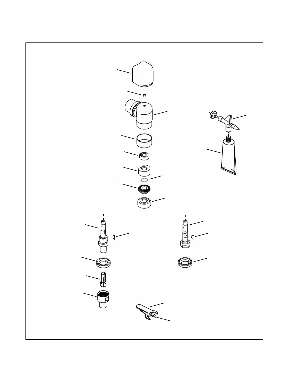
Grease:
Air Supply Line:
Service and Repair:
Tool service and repair should be performed by an
authorized Apex Tool Group, LLC or Apex Tool Group
GmbH & Co. OHG Center. Refer to the last page of this
manual for locations.
Disposal:
Observe local disposal guidelines for all
components of this tool and its packaging.
Copyright Protection:
Apex Tool Group, LLC or Apex Tool Group GmbH &
Co. OHG reserves the right to modify, supplement or
improve this document or the product without prior
notice. This document may not be reproduced in any
way, shape or form, in full or parts thereof, or copied to
another natural or machine readable language or to a
data carrier, whether electronic, mechanical, optical or
otherwise without the express permission of Apex Tool
Group, LLC or Apex Tool Group GmbH & Co. OHG
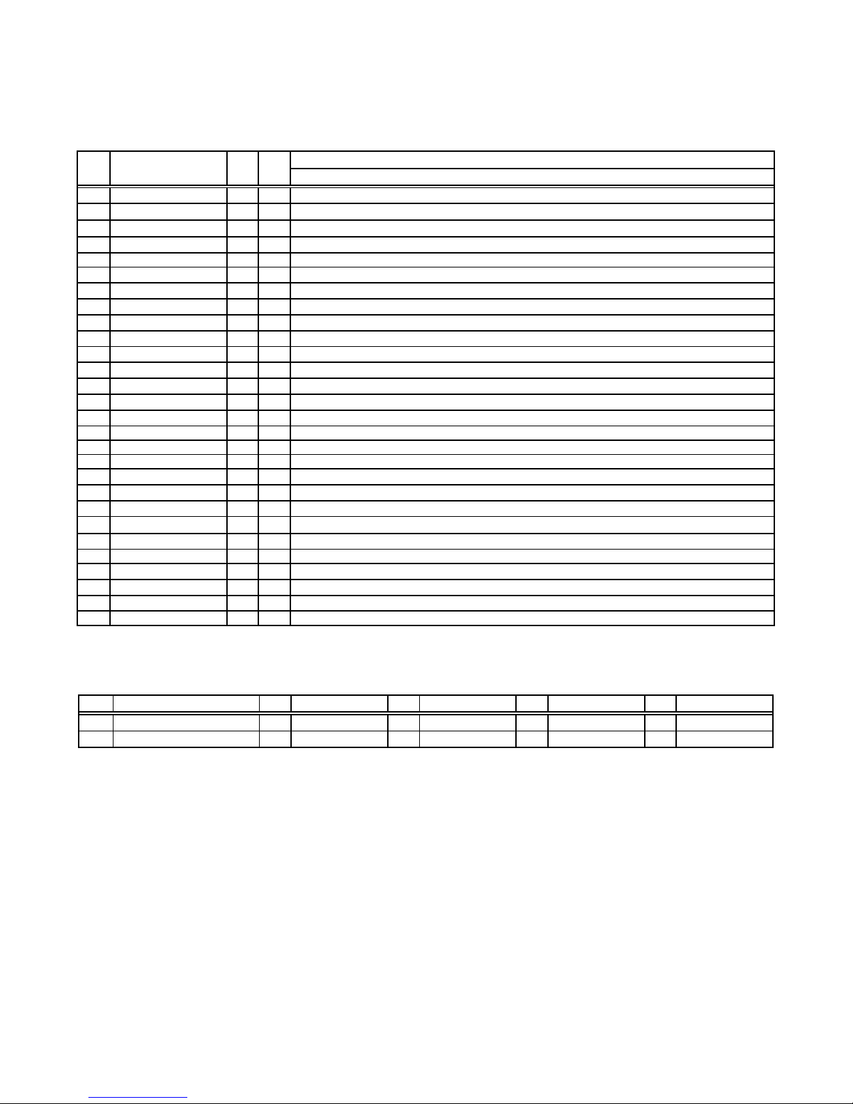
WARNING
Part No. Packaged Designation
540397 1 Quart (0.94 liter) Airlube 10W/NR-420LB DR
533485 1 US Gallon (3.78 liter) Airlube 10W/NR-420LB DR
Parameter Description
Air Hose
Minimum inside diameter: 1/4" (6,4 mm)
Maximum length: 8.0' (2,4 m)
Air Pressure Recommended: 90 psi (620 kPa)
Compressed air
Air quality according to ISO 8573-1, quality
class 2.4.3
The compressed air must be clean and dry.
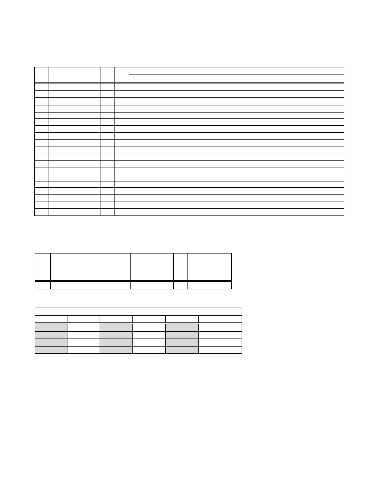
Part No. Packaged Designation
45-0980 2 oz. (0.06 kg) Angle Head: Moly-XL SAE 250
540395 2 oz. (0.06 kg) Planetary: Magnalube-G
513156 16 oz. (0.45 kg) Planetary: Magnalube-G