Dotco 15LS251 User manual

For additional product information visit our website at http://www.apextoolgroup.com
Parts Manual
45-8400
PL31-15LS2
04/21/2011
15LS, 15LN, 15SS & 15SN Series
Right Angle Drills
15 L X 2 X X - X X
Product Classification
15 = Drill
Trottle Type
L= Locking Lever
Motor Size
S = 0.6 hp
N = 0.9 hp
Handle Style
2 = Right Angle
Exhaust Type
5 = Front Exhaust
8 = Rear Exhaust
Speed Options (RPM)
500 Angle Head
600, 700, 45°, 360° Angle Heads
15LS/15LN 15LS/15LN
1 = 3,800/3,500 1 = 5,430/5,000
2 = 2,360/2,170 2 = 3,370/3,100
3 = 1,410/1,300 3 = 2,010/1,850
4 = 1,160/1,070 4 = 1,660/1,530
5 = 950/870 5 = 1,360/----
6 = 590/540 6 = 840/----
7 = 350/320 7 = 500/----
8 = ---/4,200 8 = ----/6,000
Termination Code: Angle Head Type
4 = 45° Mini Angle Head 7 = 700 Series Angle Head
5 = 500 Series Angle Head 9 = 360° Mini Angle Head
6 = 600 Series Angle Head
Termination Code: Output Type
1 = #10-32 Output Spindle 4 = 5/16-24 Output Spindle
2 = 1/4-28 Output Spindle 9 = 1/4 Capacity 3 Jaw Chuck (500 series head)
3 = 9/32-40 Output Spindle

PL31--15LS2
02/00
Page 2
SAFETY FIRST!
ALWAYS COMPLY WITH:
1. General Industry Safety & Health Regulations, Part
1910, OSHA 2206, available from: Sup’t of Documents;
Government Printing Office; Washington DC 20402
2. Safety Code for Portable Air Tools, ANSI B186.1
available from: American National Standards Institute,
Inc.; 1430 Broadway; New York, NY 10018
3. State and Local regulations.
Portions of the above codes and regulations are listed below
for quick reference.
THESE EXCERPTS ARE NOT INTENDED TO BE ALL
INCLUSIVE -- STUDY AND COMPLY WITH ALL
REGULATIONS!
WARNING FAILURE TO COMPLY WITH ALL SAFETY
REGULATIONS MAY RESULT IN SERIOUS INJURY.
1. TOOL INTENT — Tools shall be used only for purposes
intended in their design (refer to product catalog).
2. AIR SUPPLY — Test and operate tools at 90 PSIG
maximum unless tool is marked otherwise. Use
recommended airline filters—regulators—lubricators.
3. UNUSUAL SOUND or VIBRATION — If tool vibrates or
produces an unusual sound, repair immediately for
correction.
4. OPERATOR PROTECTIVE EQUIPMENT — Wear
goggles or face shield at all times tool is in operation.
Other protective clothing shall be worn, if necessary.
SEE REGULATIONS.
5. SAFETY MAINTENANCE PROGRAM — Employ a
safety program to provide inspection and maintenance
of all phases of tool operation and air supply equipment
in accordance with “Safety Code for Portable Air Tools.”
Safe Work Practices Symbol
WARNING The signal word “Warning” identifies all notes on safe
work practices in this operating instruction, alerting to hazards for life
and health of people. Observe these notes and proceed with special
care in the cases described. Pass all safety instructions on to other
operators. In addition to the safety instructions in this operating
instruction, the general local safety and accident prevention rules must
be observed.
Important Notes
CAUTION The signal word “caution!” identifies all portions of this
operating instruction meriting special attention to ensure that
guidelines, rules, hints and the correct work procedures are observed;
and, to prevent damage to and destruction of the machine and/or parts.
1The number in a square is a “service note” reference indicating
additional information for the correct assembly or disassembly of this
product. See Service Note page at end of this manual.
(•) Indicates recommended spare part (or set) for every five (5)
tools. Small, low cost or easily lost parts should be stocked as 3-4
per 10 tools.
WARNING Disconnect the air supply hose before servicing the tool.
INSTALLATION & OPERATION
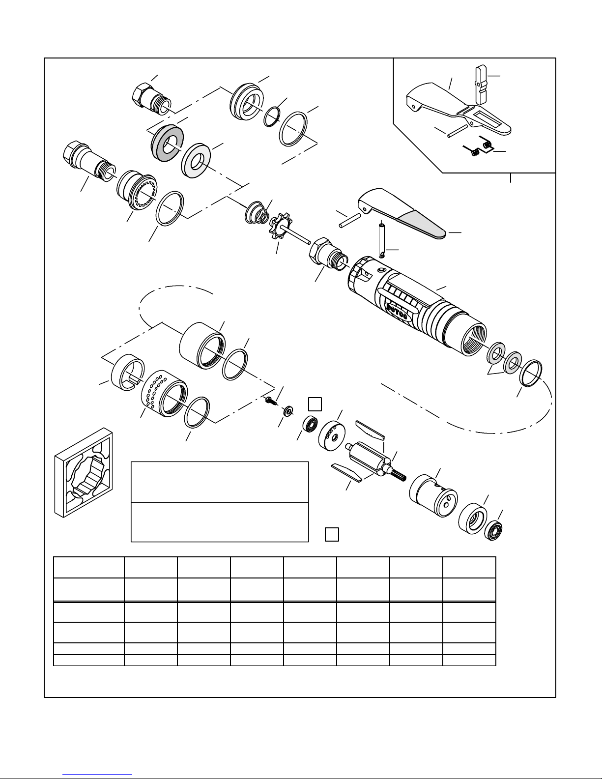
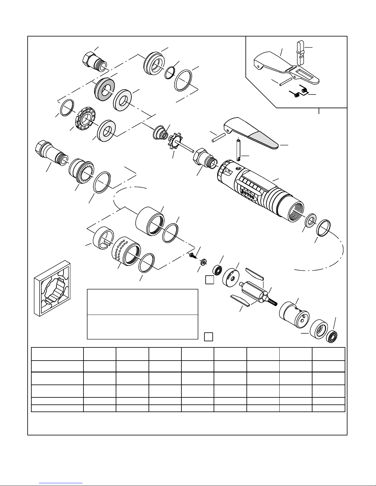
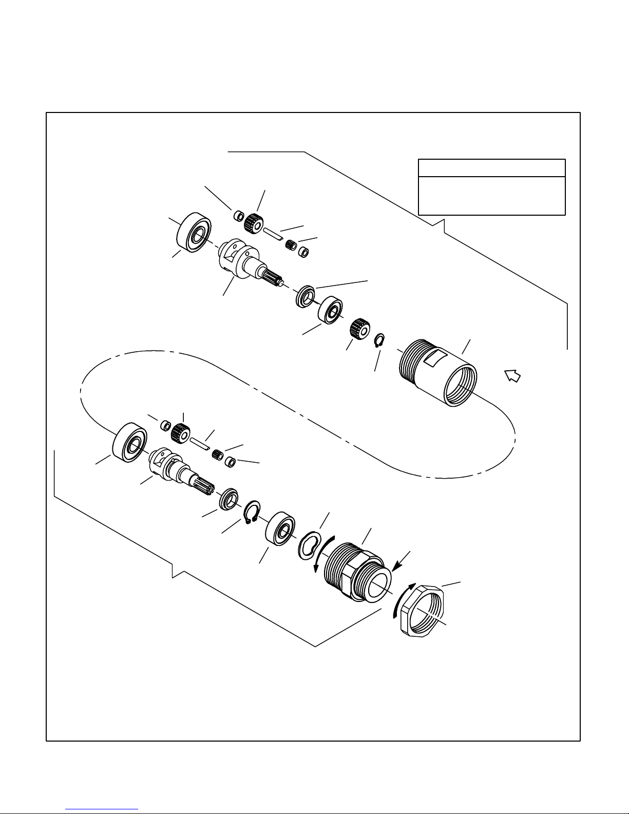
All 15LN2.. & 15LS2.. models covered by this
parts list...
These models are lever operated horizontal--type motors
with angle heads. The operator actuates and releases the
lever which starts and stops the air motor, gearing and
output spindle.
For best tool performance, a working air pressure of 90
pounds per square inch is recommended. Pipings, fit-
tings and hose should be adequate to maintain 90 psig
while the tool is in operation. An air line filter and lubri-
cator, such as Cooper Power Tool’s #F02--M Filter (1/4”
NPT) and #L02--EP Lubricator (1/4” NPT) should be used
(refer to Cooper’s “F--R--L” brochure). Hose should be
blown out before attaching to the tool.
LUBRICATION
Motor
Lubricate the motor with an air line lubricator, using a
light air tool oil. Adjust the lubricator to dispense one drop
per cycle or three drops per minute. This oil is available in
one (1) quart (540397) or one (1) gallon (533485) quanti-
ties. A high film strength oil (536333) is also available;
this oil cannot be used in Atomist type lubricators, use
only with Economist or serv-oil type lubricators.
Planetary Gearing
Thoroughly grease all gears with Cooper Power Tools
teflon grease every 100,000 cycles. Whenever the tool is
disassembled, pack the gearing with approximately 1/4
ounce of grease. Teflon grease is available in one (1)
pound cans (513156) or two (2) oz. tube (540395).
Establish a routine inspection and re--lubrication program,
don’t short cut. Re--lubricate planetary by filling 1/3 to
1/2 full. Midget grease fittings are provided on the gear
housings and internal gears for external lubrication. Too
much grease will cause overheating.
CAUTION Do not use substitutes for oil and
grease. This could result in damage to the tool.
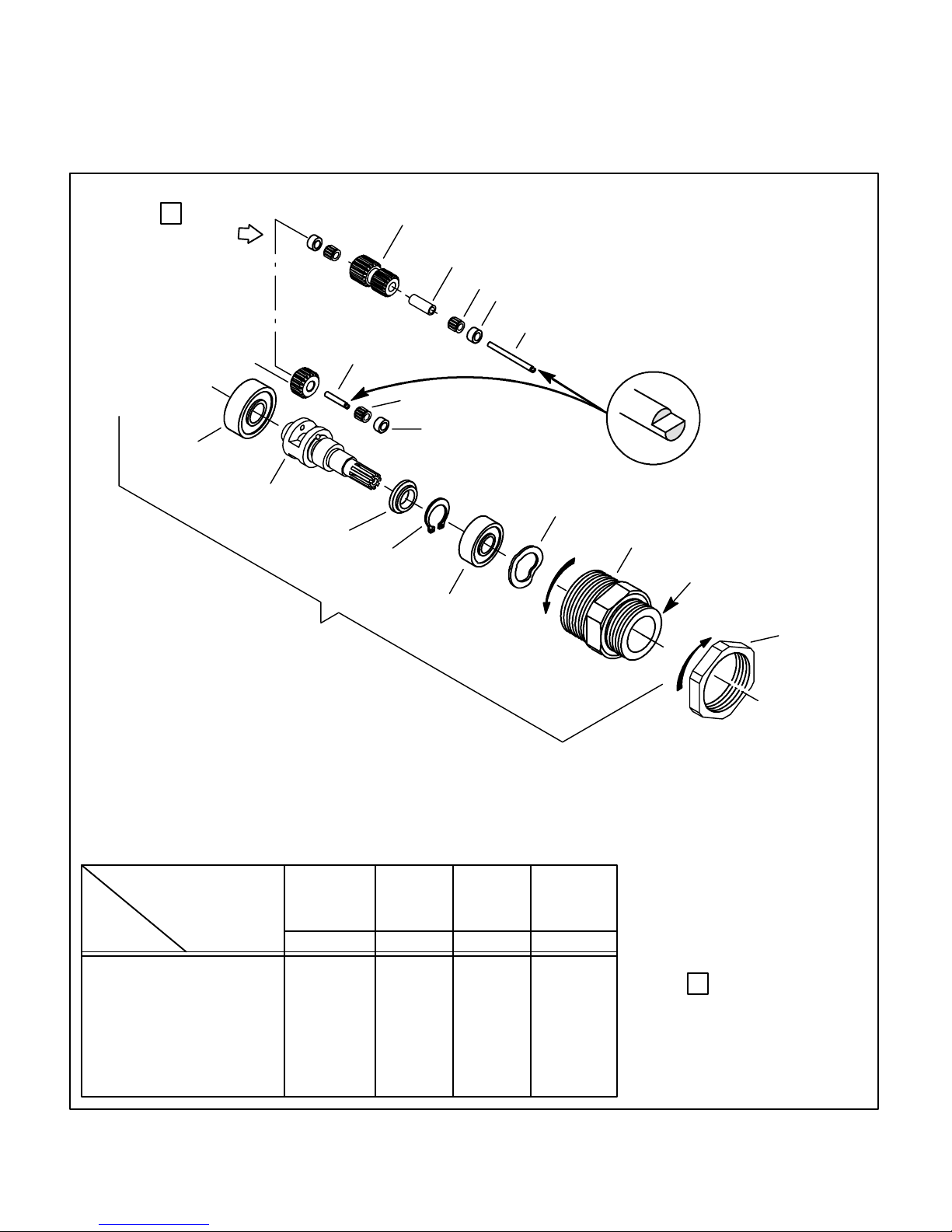
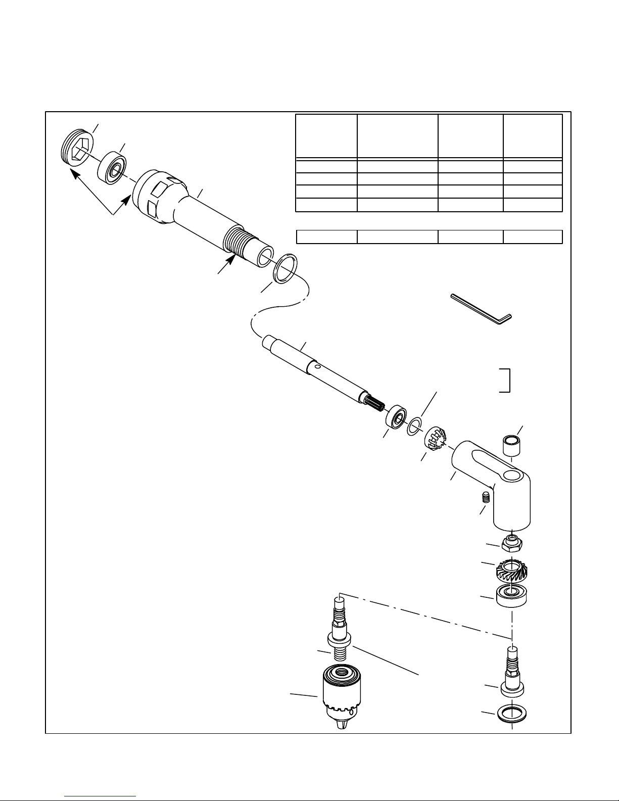
Angle Head Gear Lubrication
When angle head gearing is replaced, wipe on a thin coat
of Molykote, grade G; only a small amount is necessary.
An 8 ounce tube is available under part number 540394.
Molykote has been shown to improve the wearing
characteristics of angle gearing.

PL31--15LS2
02/00
Page 3
#45--1982
Grease Gun
PARTS INSPECTION
1. Wash all parts except ball bearings in solvent. Dry and
place on a clean cloth for inspection.
2. Check ball bearings for wear. Bearings should turn
smoothly with no appreciable shake or looseness.
3. Check rotor blades for wear by comparing with a new
blade. Replace if worn more than 1/32” in height.
4. Check motor cylinder for grooves, gouges or pitting.
Honing is permissible, however, never remove more than
about 0.001” or 0.002” of material. Replacement is usual-
ly recommended.
SERVICE NOTE 1:
.001” Clearance
Rotor
Hardwood
Block
Hold the rotor and rear plate assembly vertically (plate
downward) and strike the edge of the plate with a wood block.
This helps seat the threaded components.
Caution! Begin tightening the rotor screw but do not over-tighten. This
could cause damage to the bearing. Alternately spin the rotor while
tightening the screw until a clearance of approximately 0.001” is achieved.
Rear Plate
Ball
Bearing
Rotor
Screw
Assemble rotor to rear plate/bearing assembly with the rotor’s retaining
screw. Position and set the rotor as close as possible to the rear plate,
without dragging or rubbing.
a. A good practice is to stone the blade slots and polish the ends with a
medium grit emery cloth.
b. Assemble components making sure the bearing is firmly seated in the
rear plate.
1
SERVICE NOTE 2:
X
X
DRILL POINT STAMPED “X”
For Speed Code 4 Models
EXAMPLE:
15LS284..
Assemble the planet gears into the planet cage, making sure the notched
planet pins fit over the planet cage washer. Rotate each gear until the
aligning hole — on the end of one gear — is diametrically opposite the “X”
mark of the other gear. Hold the gears in this position and slip the planet
cage into the internal gear. This is important to avoid “wiping out” the gear
teeth.
This is the only position where the gear teeth are lined up.
TIMING OF THE STEP REDUCTION GEAR ASSEMBLY
2
DOTCO15LS2.. & 15LN2.. Series
SERVICE NOTES

“OIL--LESS” ROTOR BLADES
“Oil--Less” rotor blades can be assembled in
tools at extra cost, as follows.
Part Num. Description
1019724
1025413
(4 each) blades installed by factory in
tools. Order in tool by adding NL to end
of model code.
Package of 100 (not assembled in tools)
DOTCO
15LS Series (0.6hp) Motor & Motor Housing Assemblies
14--0851 (12 pt)
Housing Wrench
01--1020 Lever
01--2517 Push Rod
•01--1169 O--Ring
•01--1169 O--Ring
•01--2061
Muffler Felt
•1011750 Rotor Screw
•1010183 Ball Bearing
•1110068
Rear Plate
•1008309 Cylinder
•1008256
Rotor Blade
(4 required)
•1008260
Front Plate
•1010770
Ball Bearing
*Rotor
01--2062
Muffler Body
01--2063 Muffler
REAR
EXHAUST
FRONT
EXHAUST
01--2505 Inlet Adapter
(1/4” NPT) 01--2506
Exhaust Plug
•2965 O--Ring
•3036 O--Ring
1042
Pin
01--2519
Valve Spring
01--2518
Valve
01--2504
Valve Seat
01--2520
Diffuser
01--1031
Inlet
Adapter
01--1032 Muffler
•3036 O--Ring
FRONT
EXHAUST
•1110134
Muffler
(•) Indicates recommended spare part. Order one (1) or one set for every 6--10 tools. Small, easily lost or low cost parts should also be
ordered on the basis of 3--4 per 10 tools.
01--1259
Lock Off
01--1237
Lever
01--1241
Pin
01--1240
Spring
01--1260 Lock Off
Lever Assembly
15S series
REAR EXHAUST
WITH OVERHOSE
REAR
EXHAUST
1See Service Notes
1
1012518 Washer
•1110134
Muffler
01--2074
Spacer
01--2081 Motor Housing
PL31--15LS2
02/00
Page 4
(*)
PART NAME 15LS251
15LS281
15LS252
15LS282
15LS253
15LS283
15LS254
15LS284
15LS255
15LS285
15LS256
15LS286
15LS257
15LS287
rpm: TERM. 50 series
TERM. 40, 60, 70, 90
ser.
3800
5430
2360
3370
1410
2010
1160
1660
950
1360
590
840
350
500
Rotor
(num. teeth)
1012811
—
1012769
(9T)
1012812
(5T)
1012812
(5T)
102811
—
1012769
(9T)
1012812
(5T)
Motor Assembly
(complete) 1025561 1025565 1025566 1025566 1025561 1025565 1025566
Pinion 1021745 ———1021745 — —
Retaining Ring 1007548 ———1007548 — —
(T)Teeth•Zähne •Dents •Dientes •Denti

•1110134
Muffler
“OIL--LESS” ROTOR BLADES
“Oil--Less” rotor blades can be assembled in
tools at extra cost, as follows.
Part Num. Description
1019882
1025484
(4 each) blades installed by factory in
tools. Order in tool by adding NL to end
of model code.
Package of 100 (not assembled in tools)
DOTCO
15LN Series (0.9hp) Motor & Motor Housing Assemblies
14--0851
12 pt
Housing Wrench
01--1020 Lever
01--2517 Push Rod
•01--1169 O--Ring
•01--1169 O--Ring
•01--2061
Muffler Felt
•1011750 Rotor Screw
•1010183 Ball Bearing
•1110068 Rear Plate
•1019667 Cylinder
•1017119
Rotor Blade
(4 required)
•1008260
Front Plate
•1010770
Ball Bearing
*Rotor
01--2062
Muffler Body
01--2063 Muffler
REAR
EXHAUST
FRONT EXHAUST
01--2505 Inlet Adapter
(1/4” NPT) 01--2506
Exhaust Plug
•2965 O--Ring
•3036 O--Ring
01--2074
Spacer
1042
Pin
01--2519
Valve Spring
01--2518
Valve
01--2504
Valve Seat
01--2520
Diffuser
01--1031
Inlet
Adapter
01--1032 Muffler
•3036 O--Ring
FRONT
EXHAUST
•1110134
Muffler
(•) Indicates recommended spare part. Order one (1) or one set for every 6--10 tools.
Small, easily lost or low cost parts should also be ordered on the basis of 3--4 per 10 tools.
01--1259
Lock Off
01--1237
Lever
01--1241
Pin
01--1240
Spring
01--1260 Lock Off
Lever Assembly
15S series
REAR EXHAUST
WITH OVERHOSE
REAR
EXHAUST
1See Service Notes
1
15LN288,
15SN288
ONLY
•11--014
O--Ring
1111040
Diffuser •1110135
Muffler
1012518 Washer
01--2584 Motor Housing
PL31--15LS2
02/00
Page 5
(*)
PART NAME 15LN251
15LN281
15LN252
15LN282
15LN253
15LN283
15LN254
15LN284
15LN255
15LN285
15LN256
15LN286
15LN257
15LN287
15LN258
15LN288
rpm: TERM. 50 series
TERM. 40, 60, 70, 90 ser.
3500
5000
2170
3100
1300
1850
1070
1530
870
—
540
—
320
—
4200
6000
Rotor
(num. teeth)
1017218
—
1017156
(9T)
1017184
(5T)
1017184
(5T)
107218
—
1017156
(9T)
1017184
(5T)
1017218
—
Motor Assembly
(complete) 1025570 1025571 1025572 1025572 1025570 1025571 1025572 1025639
Pinion 1021745 — — — 1021745 — — 1017625
Retaining Ring 1007548 — — — 1007548 — — 1007548
(T)Teeth•Zähne •Dents •Dientes •Denti

PL31--15LS2
02/00
Page 6
Model 15LN & 15LS Angle Drills
Planetary Gearing
DOTCO
(S) Indicates recommended spare
part. Order one (1) or one set for
every 6--10 tools. Small, easily lost or
low cost parts should also be ordered
on the basis of 3--4 per 10 tools.
GEAR ASSEMBLY (Complete)
Pl. Cage Washer
(diameter):
Gear Housing
(num. teeth)
Planet Cage
Planet Gears (2 ea.)
(num. teeth)
Planet Pins (2 req’d)
1025934
1110069
(0.743”)
1110040
(48T)
1110228
1008250
(16T)
1004983
1025655
1110070
(0.677”)
1110042
(49T)
1110229
1008252
(19T)
1004983
1025656
1110071
(0.636”)
1110042
(49T)
1110231
1110139
(21T)
1004983
1025657
1110071
(0.636”)
1110063
(43T)
1110226
1008952
(21T/15T)
1005010
1234Speed Code:
Part Name
MODEL:
(*)
15LN251
15LN281
15LS251
15LS281
15LN252
15LN282
15LS252
15LS282
15LN253
15LN283
15LS253
15LS283
15LN254
15LN284
15LS254
15LS284
Single Stage Gearing
1008262
Ball
Bearing
1110127 Wave Washer
1008854
Ball Bearing
1010099 Retaining Ring
*Planet Pin (2 Required)
*Planet Cage
*Planet Cage Washer Gear Housing (48T)
(Incl: 1463 Grease Fitting)
*Planet Gear
(2 Req’d)
1”--20 (LH thread)
•
•OUTPUT GEARING:
Install Planet Pin with
notch oriented as shown.
•7610 Needle Bearing
(2 req’d)
1110066 Washer
(4 req’d -- 2 per gear)
OUTPUT PLANETARY
GEARING ASSEMBLIES --
See Chart
1005010 Planet Pin
(2 required)
1110066 Washer (4 req’d: 2 per gear)
7610 Needle Bearing (4 req’d: 2 per gear)
1110571 Spacer (2 req’d: 1 per gear)
1008952 Planet Gear
(15T & 21T)
(2 required)
•
CODE 4
ONLY
1110065
Lock Nut
2
2
See Service Notes
OFF
AUS
FERMÉ
APAGADO
SPENTO
OFF
AUS
FERMÉ
APAGADO
SPENTO

PL31--15LS2
02/00
Page 7
Model 15LN & 15LS Angle Drills
Planetary Gearing
DOTCO
(S) Indicates recommended spare part.
Order one (1) or one set for every 6--10 tools.
Small, easily lost or low cost parts should also
be ordered on the basis of 3--4 per 10 tools.
Double Stage Gearing
GEAR HOUSING, (Incl: #1463
Grease Fitting)
1008955 (48T) -- CODE 5
1008956 (49T) -- CODE 6, 7
1008262
Ball Bearing
•
•
1004983 Planet Pin (2 Required)
•
1005062
Ball Bearing
•
PLANET GEAR ( 2 Req’d)
1008250 (16T) -- CODE 5
1008252 (19T) -- CODE 6
1110139 (21T) -- CODE 7
PLANET CAGE WASHER
1017051 -- CODE 5
1017053 -- CODE 6
1110138 -- CODE 7
1008262
Ball
Bearing
1110127 Wave Washer
1008854
Ball Bearing
1007964
Retaining Ring
1004983
Planet Pin (2 Required)
1110228
Planet Cage
1110069 Planet Cage
Washer
1110040 Gear Housing (48T)
(Incl: 1463 Grease Fitting)
1008250 Planet
Gear (16T)
(2 Req’d)
1”--20 (LH thread)
PLANET CAGE
1017842 -- CODE 5
1017841 -- CODE 6
1110141 -- CODE 7
PRIMARY
PLANETARY
GEARING
ASSEMBLIES --
See Chart
(above)
1017856
Detachable
Pinion 1007548
Retaining
Ring
•
•
•
7610 Needle Bearing
(2 req’d)
1110066 Washer
(4 req’d, 2 per gear)
1025654
OUTPUT PLANETARY
GEARING ASSEMBLY
PRIMARY GEAR ASSEMBLIES
Code 5 -- 1025583
Code 6 -- 1025584
Code 7 -- 1025605
OFF
AUS
FERMÉ
APAGADO
SPENTO
OFF
AUS
FERMÉ
APAGADO
SPENTO
1110065
Lock Nut
•7610 Needle Bearing
(2 req’d)
1110066 Washer (4 req’d)
2 per gear)

PL31--15LS2
02/00
Page 8
1”--20
LH Thread
Model 15LN288 (0.9hp) Angle Drill
4200 or 6000 RPM Planetary Gearing
DOTCO
(S) Indicates recommended
spare part. Order one (1) or one
set for every 6--10 tools. Small,
easily lost or low cost parts
should also be ordered on the
basis of 3--4 per 10 tools.
1017621 Planet Gear (2 Req’d) (15T)
1110066 Washer (4 required --
2 per gear)
•1008262
Ball Bearing •1008854 Ball Bearing
1110065
Lock Nut
•7610 Needle Bearing (2 required)
1110064 Planet Cage
1110042 Nose & Internal Gear
(49 teeth)
•1004983 Planet Pin (2 required)
OFF •AUS •FERMÉ •
APAGADO •SPENTO OFF •AUS •FERMÉ •
APAGADO •SPENTO

PL31--15LS2
02/00
Page 9
Angle Head
Assembly
Part Number
Assembly Includes
Output Spindle
Part Number
Spindle
Thread Size
(Internal)
1025547
1021289
1021292
1021291
1110062
1008850
1008948
1008856
#10--32
1/4”--28
9/32”--40
5/16”--24
Termination
Code
-- 5 1
-- 5 2
-- 5 3
-- 5 4
LUBRICATION
Only Molykote is recommended for use in these
angle heads. Wipe on only a small amount and
remove any excess.
REASSEMBLY (With new components)
Rebuild the output spindle components using a
NEW #1008849 Nut. Lightly coat the bevel gear
with Molykote and install in the angle head. No
shims are required between these components.
Shimming:
Next, place Ball Bearing (part #1007537), one
0.002” shim (part #1008748) and bevel pinion on
end of spindle extension (part #1009643).
Normally, only one shim is all that is required.
Wipe a small amount of Molykote on bevel pinion
and install in housing, threading housing and
angle head together.
Checking gear mesh:
Hold end of spindle extension with fingers and
turn output spindle back--and--forth. Acceptable
play is 0.005” or less. Add only one shim at a
time (or, take out one shim) until play is correct.
LH thread
1”--20
LH Thread
•1005062 Ball Bearing
1009242 Housing
•1008680 O--Ring
•1011671
Needle
Bearing
1008853
Angle Head
•1008849 Nut
•1008854 Ball Bearing
Output Spindle
(see chart above)
1008859
Retaining Ring
1009643 Spindle Extension
•1007537 Ball Bearing
•1009255 Bevel Pinion
1006205 Retaining Nut
1008345 Set Screw
1008748 Shim — 0.002”
1013224 Shim — 0.005”
As
Required
1008863
Hex Wrench (1/8”)
•1009095 Bevel Gear
=
(=) NOTE: ALWAYS replace Bevel
Gear and Bevel Pinion IN PAIRS since
both should wear equally.
=
Models 15LS & 15LN Angle Drills
90º Heavy Duty Angle Head
DOTCO
1021620 1015703 3/8”--24 -- 5 9
Male thread
1005078 Drill Chuck
1/4” capacity (includes
#1005079 Chuck Key).
Chuck not included in
angle head
TERM. 59
(S) Indicates recommended
spare part. Order one (1) or one
set for every 6--10 tools. Small,
easily lost or low cost parts
should also be ordered on the
basis of 3--4 per 10 tools.
3/8”--24
thread

PL31--15LS2
02/00
Page 10
Angle Head
Assembly
Part Number
Assembly
Includes
Output Spindle
Part Number
Spindle
Thread Size
(Internal)
1025314
1025409
1025313
1025328
1019553
1019551
1019552
1019554
#10--32
1/4”--28
9/32”--40
5/16”--24
-- 6 1
-- 6 2
-- 6 3
-- 6 4
LUBRICATION
Only Molykote is recommended for use in these angle heads.
Wipe on only a small amount and remove any excess.
REASSEMBLY (With new components)
1. Start with only one 0.002” shim (part #1006265) above work
spindle in bearing pocket. Assemble all output spindle
components, applying Molykote, and tighten bearing cap to 15
inch--pounds torque.
This is for end play only. With too much play, take out the
0.003” shim. A slight back--and--forth amount of play is
acceptable and necessary.
2. Assemble all remaining components and check gear
“shake”. This is for gear mesh which should be no more than
0.005”.
3. Be sure to apply Molykote before assembly.
1019759 Spanner Wrench (service
wrench not supplied with angle
head assembly).
Fits #1019569 Bearing Cap
1009643 Spindle Extension
•1019559 Ball Bearing
•1019555 Bevel Gear
1006205 Retaining Nut
=
•1009087 Ball Bearing
1008748 Shim — 0.002”
1013224 Shim — 0.005”
As
Required
1019569 Bearing Cap
(LH Thread)
1019556 Angle Head
(Includes #1008992
Grease Fitting)
•Output Spindle
(see chart, above)
1”--20
LH Thread
•1019559 Ball Bearing
1006265 Shim (0.002”)
1006266 Shim (0.003”)
1006267 Shim (0.005”)
As Required
=
(=) NOTE: ALWAYS replace Bevel
Gear and Output Spindle IN PAIRS
since both should wear equally.
Tighten to 15
Inch Pounds torque.
3/8” Hex
•1019560 Ball Bearing
Models 15LS & 15LN Angle Drills
90º Miniature Angle Heads
DOTCO
Termination
Code
(S) Indicates recommended spare part. Order
one (1) or one set for every 6--10 tools. Small,
easily lost or low cost parts should also be
ordered on the basis of 3--4 per 10 tools.

PL31--15LS2
02/00
Page 11
Angle Head
Assembly
Part Number
Assembly
Includes
Output Spindle
Part Number
Spindle
Thread Size
(Internal)
1025667
1025477
1025476
1025668
1110261
1019879
1019880
1110262
#10--32
1/4”--28
9/32”--40
5/16”--24
Termination
Code
-- 7 1
-- 7 2
-- 7 3
-- 7 4
LUBRICATION
Only Molykote is recommended for use in
BUCKEYE angle heads. Wipe on only a small
amount and remove any excess.
1019759 Spanner Wrench (service
wrench not supplied with angle
head assembly).
Fits #1019569 Bearing Cap
1009643 Spindle Extension
•1019559 Ball Bearing
•1019555 Bevel Gear
1006205 Retaining Nut
=
•1009087 Ball Bearing
1008748 Shim — 0.002”
1013224 Shim — 0.005”
As
Required
1019758 Angle Head
1”--20
LH Thread
(=) NOTE: ALWAYS replace Bevel
Gear and Output Spindle IN PAIRS
since both should wear equally.
1019569 Bearing Cap
Output Spindle
(see chart, above)
=
Tighten to 15
Inch Pounds torque.
1011597 Bushing
•1019559 Ball Bearing
3/8” Hex
1”--20
LH Thread
LH Thread
Models 15LS & 15LN Angle Drills
90º Compact Angle Heads
DOTCO
(S) Indicates recommended spare part. Order
one (1) or one set for every 6--10 tools. Small,
easily lost or low cost parts should also be
ordered on the basis of 3--4 per 10 tools.

PL31--15LS2
02/00
Page 12
45°ATTACHMENT
Angle Head
Assembly
Part Number
Assembly
Includes
Output Spindle
Part Number
Spindle
Thread Size
(Internal)
1025732
1025730
1025731
1025733
1110351
1110349
1110350
1110352
#10--32
1/4”--28
9/32”--40
5/16”--24
-- 4 1
-- 4 2
-- 4 3
-- 4 4
45°ANGLE HEAD ASSEMBLIES
•1019559 Ball Bearing
•1110353 Pinion Gear
=
1008748 Shim — 0.002”
1013224 Shim — 0.005”
As
Required
•Output Spindle
(see chart)
=
(=) NOTE: ALWAYS replace Bevel
Gear and Output Spindle IN PAIRS
since both should wear equally.
•1019560 Ball Bearing
1110406 Angle Head
1463 Grease Fitting
•1019560 Ball Bearing
•1005823
Steel Ball
1110354 Spacer
1019569
Bearing Cap
(LH Thread)
1006205 Retaining Nut
(1”--20 LH Thread)
•1009087 Ball Bearing
1009643 Spindle Extension
1019759 Spanner Wrench (service
wrench not supplied with angle
head assembly).
Fits #1019569 Bearing Cap
3/8” Hex
LH
Thread
Models 15LS & 15LN Angle Drills
45º Mini Angle Heads
DOTCO
(S) Indicates recommended spare part. Order
one (1) or one set for every 6--10 tools. Small,
easily lost or low cost parts should also be
ordered on the basis of 3--4 per 10 tools.
Termination
Code

PL31--15LS2
02/00
Page 13
1019759 Spanner Wrench
(service wrench not
supplied with angle head
assembly).
Fits #1019569 Bearing Cap
1009643 Spindle Extension
•1019559 Ball Bearing
•1019555 Bevel Gear
1006205
Retaining Nut
(LH THREAD)
=
•1009087 Ball Bearing
1019569 Bearing Cap
(LH Thread)
1019556 Angle Head
(Includes #1008992
Grease Fitting)
•1019551
Output Spindle
1”--20
LH Thread
•1019559 Ball Bearing
=
(=) NOTE: ALWAYS replace Bevel
Gear and Output Spindle IN PAIRS
since both should wear equally.
Tighten to 15
Inch Pounds torque.
3/8” Hex
•1019560 Ball Bearing
•1019559 Ball Bearing
1110331
Spindle Extension
360°ATTACHMENT
Angle Head
Assembly
Part Number
Spindle
Thread Size
(Internal)
1025696
1025694
1025695
1025697
#10--32
1/4”--28
9/32”--40
5/16”--24
360°ANGLE HEAD ASSEMBLIES
#1006265 — 0.002”
1006266 — 0.003”
1006267 — 0.005”
#1016150 — 0.005”
1016151 — 0.002”
(*)
(**)
SHIM — as required for gear mesh
SHIM(s)**
•1019560
Ball Bearing
SHIM(s)*
SHIM(s)*
•1019559 Ball Bearing
=
•1019555 Bevel Gear
1110333
Clamp
1008671
Screw (2)
1110332
Bearing Locknut
(LH Thd)
1110330
Angle Head
=(LH Thread)
-- 9 1
-- 9 2
-- 9 3
-- 9 4
(S) Indicates recommended spare part. Order
one (1) or one set for every 6--10 tools. Small,
easily lost or low cost parts should also be
ordered on the basis of 3--4 per 10 tools.
Models 15LS & 15LN Angle Drills
360º Mini Angle Heads
DOTCO
Assembly
Includes
Output Spindle
Part Num.
1019553
1019551
1019552
1019554
Termination
Code
Work Spindle
(see chart)


Sales & Service Centers
Note: All locations may not service all products. Please contact the nearest Sales & Service Center for
the appropriate facility to handle your service requirements.
Dallas, TX Detroit, MI Houston, TX Lexington, SC
Apex Tool Group Apex Tool Group Apex Tool Group Apex Tool Group
Sales & Service Center Sales & Service Center Sales & Service Center 670 Industrial Drive
1470 Post & Paddock 2630 Superior Court 6550 West Sam Houston Lexington, SC 29072
Grand Prairie, TX 75050 Auburn Hills, MI 48326 Parkway North, Suite 200 Tel: 800-845-5629
Tel: 972-641-9563 Tel: 248-391-3700 Houston, TX 77041 Tel: 803-951-7544
Fax: 972-641-9674 Fax: 248-391-7824 Tel: 713-849-2364 Fax: 803-358-7681
Fax: 713-849-2047
Los Angeles, CA Seattle, WA York, PA Canada
Apex Tool Group Apex Tool Group Apex Tool Group Apex Tool Group
Sales & Service Center Sales & Service Center Sales & Service Center Sales & Service Center
15503 Blackburn Avenue 2865 152nd Avenue N.E. 3990 East Market Street 5925 McLaughlin Road
Norwalk, CA 90650 Redmond, WA 98052 York, PA 17402 Mississauga, Ont. L5R 1B8
Tel: 562-623-4457 Tel: 425-497-0476 Tel: 717-755-2933 Canada
Fax: 562-802-1718 Fax: 425-497-0496 Fax: 717-757-5063 Tel: 905-501-4785
Fax: 905-501-4786
Germany England France China
Cooper Power Tools Cooper Power Tools Cooper Power Tools SAS Cooper (China) Co., Ltd.
GmbH & Co. OHG GmbH & Co. OHG a company of a company of
a company of a company of Apex Tool Group, LLC Apex Tool Group, LLC
Apex Tool Group, LLC Apex Tool Group, LLC 25 rue Maurice Chevalier 955 Sheng Li Road,
Industriestraße 1 C/O Spline Gauges 77330 Ozoir-La-Ferrière Heqing Pudong, Shanghai
73463 Westhausen Piccadilly, Tamworth France China 201201
Germany Staffordshire B78 2ER Tel: +33 1 6443 2200 Tel: +86-21-28994176
Tel: +49 (0) 73 63 81 0 United Kingdom Fax: +33 1 6443 1717 Fax: +86-21-51118446
Fax: +49 (0) 73 63 81 222 Tel: +44 1827 8741 28
Fax: +44 1827 8741 28
Mexico Brazil Hungary
Cooper Tools Cooper Tools Industrial Ltda. Cooper Tools Hungaria Kft.
de México S.A. de C.V. a company of a company of
a company of Apex Tool Group, LLC Apex Tool Group, LLC
Apex Tool Group, LLC Av. Liberdade, 4055 Berkenyefa sor 7
Vialidad El Pueblito #103 Zona Industrial - Iporanga Pf: 640
Parque Industrial Querétaro 18087-170 Sorocaba 9027 Györ
Querétaro, QRO 76220 SP Brazil Hungary
Mexico Tel: +55 15 2383929 Tel: +36 96 66 1383
Tel: +52 (442) 211-3800 Fax: +55 15 2383260 Fax: +36 96 66 1135
Fax: +52 (442) 103-0443
45-8400/PL31-15LS2/Printed in USA 04/2011/Copyright © Apex Tool Group, LLC
Apex Tool Group, LLC
1000 Lufkin Road
Apex, NC 27539
Phone: 919-387-0099
Fax: 919-387-2614
www.apextoolgroup.com
This manual suits for next models
29
Table of contents
Other Dotco Nail Gun manuals
Popular Nail Gun manuals by other brands

Milwaukee
Milwaukee 7145-21 Operator's manual

Arrow
Arrow ET2025 manual

Harbor Freight Tools
Harbor Freight Tools Chicago Electric Power Tools 93241 Assembly and operating instructions

DeWalt
DeWalt D51238 instruction manual

DeWalt
DeWalt DC628-XE instruction manual

Milwaukee
Milwaukee 7120-21 Operator's manual