DOTWORKZ D2 COOLDOME Instruction sheet

THE INSTALLERS / INTEGRATORS DREAM ENCLOSURE
TableofContents
ProductInstallationPrecautionsandWarnings..............................................................................................................................................2
D2ComponentChecklistforcamerainstallation............................................................................................................................................3
Axis231D/232DSpecialBracket...............................................................................................................................................................4
RecommendedTools...............................................................................................................................................................................4
IPCameraInstallation(MountingBrackets)................................................................................................................................................5‐20
GenericCamera....................................................................................................................................................................................5
Axis213&CanonVB‐C50i‐R.................................................................................................................................................................6
Axis214...............................................................................................................................................................................................7
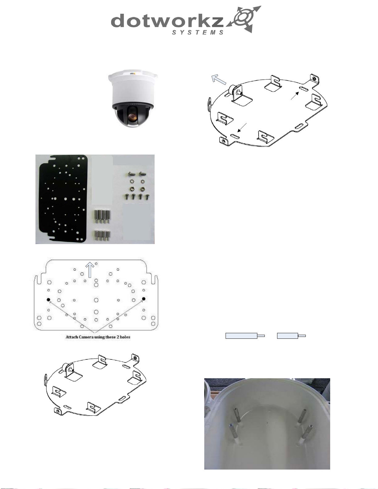
Axis231D/232D....................................................................................................................................................................................8
Axis233D........................................................................................................................................................................................9‐10
CanonVB‐C300...................................................................................................................................................................................11
PanasonicNS‐202..............................................................................................................................................................................12
PanasonicHCM381/580/581&HMC280.............................................................................................................................................13
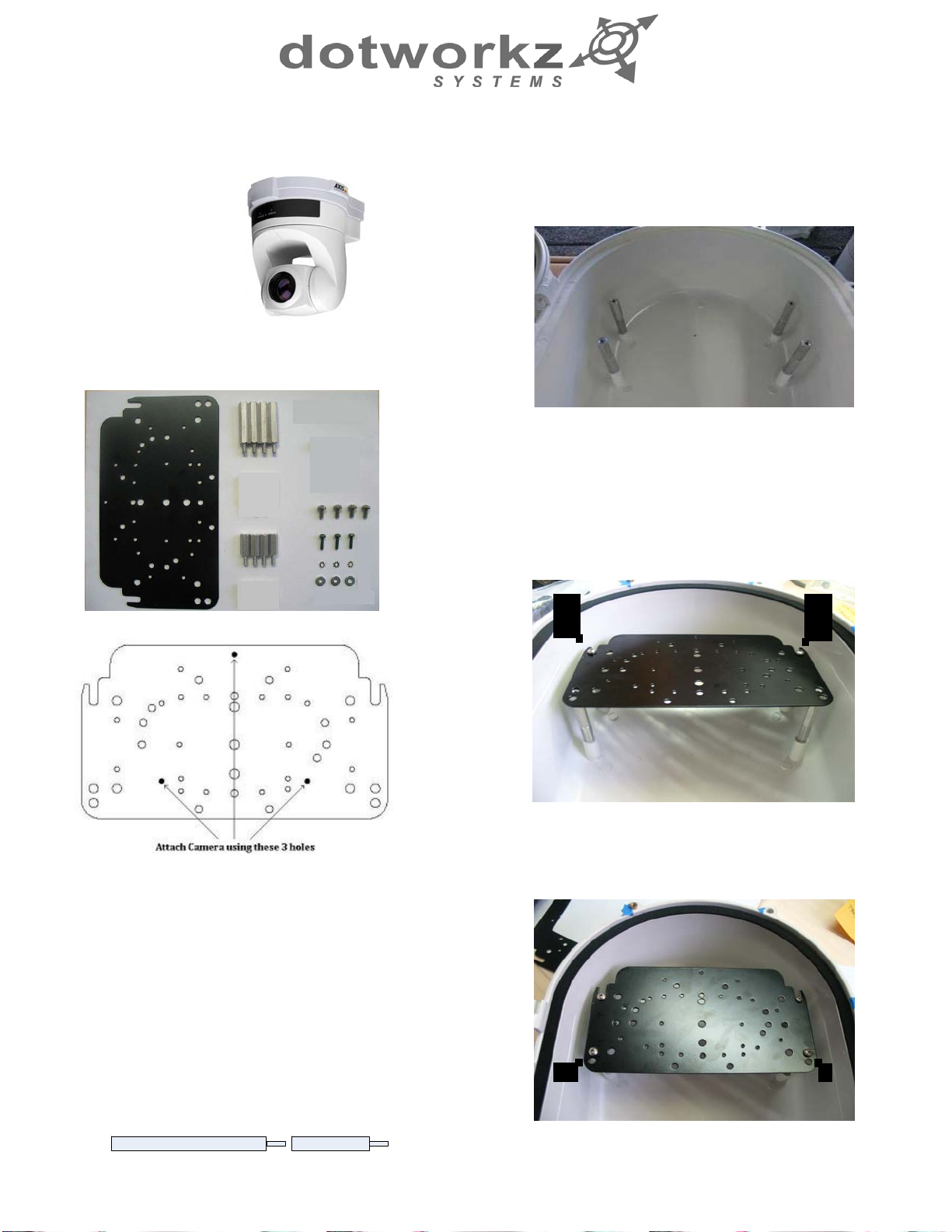
SonyRZ25N.......................................................................................................................................................................................14
SonyRZ30N.......................................................................................................................................................................................15
SonyRZ50N.......................................................................................................................................................................................16
SonyRX‐550N.....................................................................................................................................................................................17
ToshibaWB‐21A...........................................................................................................................................................................18‐19
CameraPowerSetup..............................................................................................................................................................................20‐23
Standard12VDCConnector................................................................................................................................................................20
NON‐STANDARD12VDCCONNECTOR.................................................................................................................................................21
24VAC................................................................................................................................................................................................22
DomePowerSetup.................................................................................................................................................................................23‐28
12VDC................................................................................................................................................................................................24
24VAC........................................................................................................................................................................................23&24
110VAC&220VAC.....................................................................................................................................................................23&25
CoolDomeInstallation...................................................................................................................................................................26‐28
D2ExplodedView........................................................................................................................................................................................29
D2MountingTemplate................................................................................................................................................................................30

2
PRODUCTINSTALLATION
PRECAUTIONS–WARNINGS–ADDITIONALINFORMATION
(RETAINTHISDOCUMENT)
TheExternalNutonAllelectricalwirefeedGlandsmustbetightenedtocreateaweather
tightsealpriortoputtingD2inservice.Failuretocreatethissealmayresultinwater
incursionintoenclosure.Thismayleadtoelectricalshock,productfailureanddamageto
electricalsystemsinstalledwithinenclosure,includingbutnotlimitedtodamagetocamera,
heaterandblowercircuitry,coolingcircuitryandothersystemsinstalledinunit.
Allscrewsonhingedlowermustbetightenedtocreatesealonenclosure.Failuretocreate
thissealmayresultinwaterincursionintoenclosure.Thismayleadtoelectricalshock,
failureanddamagetoelectricalsystemsinstalledwithinenclosure,includingbutnotlimited
todamagetocamera,heaterandblowercircuitry,coolingcircuitryandothersystems
installedinunit.
DonotovertightenanyScrews,StandOffs,orotherfastenersonthisunit.Failuretoheed
thiswarningwillcausedamageorfailureoftheD2enclosure.
BesuretotakeextracaretoProtectLensofunitpriortoandduringinstallation,andduring
service.Suspensionpackagingboxisahandyplatformtoprotectlensandenclosure,while
installingcameraandaccessoryelectronicsbeforeinstallation.Failuretoprotectlenswill
adverselyaffectproductperformance.

3
D2 Component Checklist
12
3
4
5
11
12
13
14
15
678
9
10
16
17
Number QTY Description Type
11CameraBracketMountPlate Aluminum
24.5"Standoffs(8‐32) Aluminum
34.75"Standoffs(8‐32) Aluminum
441.0"Standoffs(8‐32) Aluminum
541.5"Standoffs(8‐32) Aluminum
62.25"Washer StainlessSteel
71.25"LockWasher StainlessSteel
81.25"‐203/8"LongBolt(7/16socket/wrench) StainlessSteel
92#10‐321/2"LongScrew(PhillipsHead) StainlessSteel
10 2 #10ExternalLockWasher StainlessSteel
11 2 #10‐32Hexnut StainlessSteel
12 4 #8‐323/8"LongScrew(PhillipsHead) StainlessSteel
13 4 #8‐32Hexnut StainlessSteel
14 4 m3‐.51/2"LongScrew Aluminum
15 4 m3ExternalLockWasher StainlessSteel
16 4 m31/8"Washer Aluminum
17 4 m3Locknut StainlessSteel
NextPage 1 Axis231/232CameramountPlate* Aluminum
*ONLYforAxis231/232SpecificD2Enclosure

4
D2 Component Checklist
Axis 231D/232D Special Camera Bracket
Tools recommended for mounting camera
- #1 & #2 Phillips head screw driver
- #1 or smaller flat head screw driver
- 3/8 Socket wrench, nut driver, or adjustable wrench
- 5/16 Socket wrench, nut driver, or adjustable wrench
- 7/16 Socket wrench, nut driver, or adjustable wrench
- 7/32 Socket wrench, nut driver, or adjustable wrench
- 11/32 Socket wrench, nut driver, or adjustable wrench

5
5.25" H 6.16" H 7.12" H 9.13" H
Upper D2 Dome Section
Lower Lens Section
For Lower D2 Section 9.375"
max
For Upper D2 Section
6.375"
The D2 Enclosure series are designed and engineered for today’s most popular standard IP based PTZ
cameras. The combination of standoff spacing and camera bracket allows our customers to tailor the D2
Enclosure series to their specific camera needs. We have provided the necessary tools for customization with all
of our D2 Enclosure series.
The D2 Enclosure series can accommodate mini-domes and PTZ cameras as tall as 9.375 inches in height. Our
standoff combination includes supported heights of 0.50",0.75",1.00", 1.25", 1.50", 1.75", 2.00", 2.25", 2.50",
2.75", 3.00", and 3.75". These standoff heights can be applied to upper and lower mount locations based on the
height of your camera. Most cameras will often utilize a center screw hole for securing the camera onto the plate.
If your camera has other mounting capabilities, then
center the camera on our camera bracket and check to
see if it aligns with any of the pre-made holes on the
camera bracket. If it does, great you can use the pre-
made holes. If it doesn’t, you can mark the holes needed
and drill them into the camera plate (steel plate).
For power, all of our D2 Environmental Enclosure Series
come standard with a 12VDC Barrel plug with a center
pin. If you camera does not support this, then check our
section on Camera Power Setup (NON-STANDARD
CONNECTOR) for details.
Generic Camera Installation
Height Example
3.7" H

6
Installing Camera Bracket
Axis 213 PTZ
Canon VB-C50iR
1. Install the Axis 213 PTZ or Canon VB-
C50iR camera onto the D2 Camera Bracket
with (2) #10-32 screws, (2) #10 Lock
Washers, and (2) #10 Locknut that are
included.
2. The Axis 213 PTZ or Canon VB-C50iR
camera requires a 2" spacing for optimal fit
and operation. Use (1) 1.5" standoffs and (1)
.5" standoffs that are provided to create a 2"
standoff. You will need to create 4 of these
with the included hardware.
Required components (see component
checklist): Part# 1,2,3,5,6,9,10,& 11
3. The 2" standoffs will be inserted on
the lower lens portion of the D2.
1.5" .5"
4. Now slide the camera bracket with
the camera into place to line up with 4
screws from the standoffs.
5. Secure the plate by using (4) .75"
standoffs to lock the bracket in place.
The two front location will require the
use of (2) .25" washer.
This edge nests in arch at front of D2
This edge of the bracket faces back of the D2 enclosure
Picture represents standoff location & orientation.
Height of standoffs will vary depending on camera
used.
Picture represents came br et orientation & how it is
secured. Don’t’ forget to mount your camera to the D2
camera bracket based on instructions.

7
Installing Camera Bracket
Axis 214 PTZ
1. Install the Axis 214 PTZ camera onto the
D2 Camera Bracket with (3) m3-.5 screws,
(3) m3 external lock washers, and (3) m3 1/8"
washer that are included.
2. The Axis 214 PTZ camera requires a 2.25"
spacing for optimal fit and operation. Use (1)
1.5" standoffs and (1) .75" standoffs that are
provided to create a 2.25" standoff. You will
need to create 4 of these with the included
hardware.
Required components (see component
checklist): Part # 1,3,5,12,14,15,& 16
3. The 2.25" standoffs will be inserted
on the upper portion of the D2.
1.5" .75"
4. Now slide the camera bracket with
the camera into place to line up with 4
screws holes from the standoffs.
5. Use (4) #8-32 screws (Phillips head)
to secure the bracket into place.
Again, make sure the camera
bracket is facing the right
direction.
This edge nests in arch at front of D2
This edge of the bracket faces back of the D2 enclosure
Tip: Insert (2) #8-32 screws in the front two
standoffs to provide a guide to slide the
camera bracket into. The last two corner
holes should line up and be secured last.
Picture represents camera bracket orientation & how it is
secured. Don’t’ forget to mount your camera to the D2
camera bracket based on instructions.
Picture represents standoff location & orientation. Height
of standoffs will vary depending on camera used.

8

9
Installing Camera Bracket
Axis 233D PTZ
2. Do this by aligning the two holes on the D2
camera bracket with the Axis ceiling bracket
adapter. Use (2) #10-32 ½” long screws, (2)
#10 lock washers, and (2) #10-32 hex nuts
that are included to secure the axis ceiling
adapter to the D2 camera bracket.
Required components (see component
checklist): Part # 1,2,3,9,10,11,& 12
5. The 1.25" standoffs will be inserted on
the upper portion of the D2.
.5"
.75"
This edge nests in arch at front of D2
This edge of the bracket faces back of the D2 enclosure
Axis 233D Ceiling bracket that came
with the camera. *This is a required
item for installation*
Align these 2
holes with the
D2 bracket
holes for the
Axis 233D
4. The Axis 233D PTZ camera requires a
1.25" spacing for optimal fit and operation.
Use (1) .75" standoffs and (1) .5" standoffs
that are provided to create a 1.25" standoff.
You will need to create 4 of these with the
included hardware.
1. To install the Axis 233D in the D2
Enclosure we must first install the Axis 233D
ceiling bracket adapter that came with the
camera onto the D2 camera mounting plate.
Axis 233D Ceiling bracket that came with the camera.
*This is a required item for installation*
3. Next follow the Axis 233D installation
instruction to secure the camera to the ceiling
bracket adapter that is now attached to the
D2 Camera Bracket.
Picture represents standoff location & orientation.
Height of standoffs will vary depending on camera used.

10
Installing Camera Bracket
Axis 233D PTZ
6. Now slide the camera bracket with the
camera into place to line up with 4 screws
holes from the standoffs.
7. Use (4) #8-32 screws (Phillips head) to
secure the bracket into place.
Tip: Insert (2) #8-32 screws in the front two
standoffs to provide a guide to slide the
camera bracket into. The last two corner
holes should line up and be secured last.
Continued . . . . . . . .
Again, make sure the camera
bracket is facing the right
direction.
Picture represents camera bracket orientation & how it is
secured. Don’t’ forget to mount your camera to the D2
camera bracket based on instructions.
Picture represents standoff location & camera
bracket orientation. Height of standoffs will vary
depending on camera used.

11
Installing Camera Bracket
Canon VB-C300
1. Install the Canon VB-C300 camera onto
the D2 Camera Bracket center hole with (1)
.25"-20 3/8" Long Bolt, and (1) .25" Lock
Washer that are included.
2. The Canon VB-C300 camera requires a 2"
spacing for optimal fit and operation. Use (1)
1.5" standoffs and (1) .5" standoffs that are
provided to create a 2" standoff. You will
need to create 4 of these with the included
hardware.
Required components (see component
checklist): Part# 1,2,3,5,6,7,& 8
3. The 2" standoffs will be inserted on the
lower lens portion of the D2.
1.5" .5"
4. Now slide the camera bracket with the
camera into place to line up with 4 screws
from the standoffs.
5. Secure the plate by using (4) .75"
standoffs to lock the bracket in place. The
two front location will require the use of (2)
.25" washer.
This edge nests in arch at front of D2
This edge of the bracket faces back of the D2 enclosure
Picture represents standoff location & orientation.
Height of standoffs will vary depending on camera used.
Picture represents came br t orientation & how it is
secured. Don’t’ forget to mount your camera to the D2
camera bracket based on instructions.

12
Installing Camera Bracket
Panasonic NS-202
1. Install the Panasonic NS-202 camera onto
the D2 Camera Bracket center hole with (1)
.25"-20 3/8" Long Bolt, and (1) .25" Lock
Washer that are included.
2. The Panasonic NS-202 camera requires a
2.5" spacing for optimal fit and operation.
Use (1) 1.5" standoff and (1) 1.0" standoff
that are provided to create a 2.5" standoff.
You will need to create 4 of these with the
included hardware.
Required components (see component
checklist): Part# 1,2,4,5,6,7,& 8
3. The 2.5" standoffs will be inserted on
the lower lens portion of the D2.
1.5" 1.0"
4. Now slide the camera bracket with the
camera into place to line up with 4 screws
from the standoffs.
5. Secure the plate by using (4) .5"
standoffs to lock the bracket in place. The
two front location will require the use of (2)
.25" washer.
This edge nests in arch at front of D2
This edge of the bracket faces back of the D2 enclosure
Picture represents standoff location & orientation.
Height of standoffs will vary depending on camera used.
Picture represents came br t orientation & how it is
secured. Don’t’ forget to mount your camera to the D2
camera bracket based on instructions.

13
Installing Camera Bracket
Panasonic BB-HCM381/
580/581 & KX-HMC280
1. Install the Panasonic camera onto the D2
Camera Bracket center hole with (1) .25"-20
3/8" Long Bolt, and (1) .25" Lock Washer that
are included.
2. The Panasonic camera requires a 2.0"
spacing for optimal fit and operation. Use (1)
1.5" standoff and (1) .5" standoff that are
provided to create a 2.0" standoff. You will
need to create 4 of these with the included
hardware.
Required components (see component
checklist): Part# 1,2,3,5,6,7,& 8
3. The 2.0" standoffs will be inserted on
the lower lens portion of the D2.
1.5" .5"
4. Now slide the camera bracket with the
camera into place to line up with 4 screws
from the standoffs.
5. Secure the plate by using (4) .75"
standoffs to lock the bracket in place. The
two front location will require the use of (2)
.25" washer.
This edge nests in arch at front of D2
This edge of the bracket faces back of the D2 enclosure
Picture represents standoff location & orientation.
Height of standoffs will vary depending on camera used.
Picture represents came br t orientation & how it is
secured. Don’t’ forget to mount your camera to the D2
camera bracket based on instructions.

14
Installing Camera Bracket
Sony RZ25N
1. Install the Sony RZ25N camera onto the
D2 Camera Bracket with (3) m3-.5 ½” Long
screw (3) m3 External Lock Washer, and (3)
m3 1/8" Washer that are included.
Required components (see component
checklist): Part # 1,2,3,12,14,15,& 16
2. The Sony RZ25N camera requires a 1.25"
spacing for optimal fit and operation. Use (1) .75"
standoffs and (1) .5" standoffs that are provided to
create a 1.25" standoff. You will need to create 4
of these with the included hardware.
.5"
.75'
4. Now slide the camera bracket with the camera
into place to line up with 4 screws holes from the
standoffs.
5. Use (4) #8-32 screws (Phillips head) to secure
the bracket into place.
Again, make sure the camera
bracket is facing the right direction.
This edge nests in arch at front of D2
This edge of the bracket faces back of the D2 enclosure
Tip: Insert (2) #8-32 screws in the front two
standoffs to provide a guide to slide the camera
bracket into. The last two corner holes should
line up and be secured last.
3. The 1.25" standoffs will be inserted on the
upper portion of the D2.
Tip: Don not screw all the way through.
Screw them in enough to catch some thread
on all three screw locations. Once all three
screw catch enough thread, begin tightening
one at a time. Picture represents camera bracket orientation & how it is secured.
Don’t’ forget to mount your camera to the D2 camera bracket
based on instructions.
Picture represents standoff location & orientation.
Height of standoffs will vary depending on camera
used.

15
Installing Camera Bracket
Sony RZ30N
1. Install the Sony RZ30N camera onto the D2
Camera Bracket center hole with (1) .25"-20 3/
8" Long Bolt, (1) .25" Lock Washer, and (1) .25"
Washer that are included.
2. Use (1) m3-.5 ½” long screw in the second
corner hole to prevent the Sony RZ30N from
moving left and right. The screw will protrude
out from the bracket about ¼”. The Sony RZ30
should have a threaded hole that will align with
the second corner hole.
Required components (see component
checklist): Part # 1,2,3,6,7,8,12, & 14
3. The Sony RZ30N camera requires a
2.25" spacing for optimal fit and operation.
Use (1) 1.5" standoffs and (1) .75" standoffs
that are provided to create a 2.25" standoff.
You will need to create 4 of these with the
included hardware.
.75"
1.5"
5. Now slide the camera bracket with the
camera into place to line up with 4 screws
holes from the standoffs.
6. Use (4) #8-32 screws (Phillips head) to
secure the bracket into place.
Again, make sure the camera
bracket is facing the right direction.
This edge nests in arch at front of D2
This edge of the bracket faces back of the D2 enclosure
Tip: Insert (2) #8-32 screws in the front two
standoffs to provide a guide to slide the camera
bracket into. The last two corner holes should
line up and be secured last.
4. The 2.25" standoffs will be inserted on the
upper portion of the D2.
Picture represents standoff location & orientation.
Height of standoffs will vary depending on camera
used.
Picture represents camera bracket orientation & how it is secured.
Don’t’ forget to mount your camera to the D2 camera bracket based
on instructions.

16
Installing Camera Bracket
Sony RZ50N
1. Install the Sony RZ50N camera onto the
D2 Camera Bracket center hole with (1) .25"-
20 3/8" Long Bolt, (1) .25" Lock Washer, and
(1) .25" Washer that are included.
Required components (see component
checklist): Part # 1,4,5,6,7,8,& 12
4. Now slide the camera bracket with the
camera into place to line up with 4 screws
holes from the standoffs.
5. Use (4) #8-32 screws (Phillips head) to
secure the bracket into place.
Again, make sure the camera
bracket is facing the right direction.
This edge nests in arch at front of D2
This edge of the bracket faces back of the D2 enclosure
Tip: Insert (2) #8-32 screws in the front two
standoffs to provide a guide to slide the
camera bracket into. The last two corner
holes should line up and be secured last.
3. The 2.5" standoffs will be inserted on the
upper portion of the D2.
2. The Sony RZ50N camera requires a 2.5"
spacing for optimal fit and operation. Use (1)
1.5" standoffs and (1) 1" standoffs that are
provided to create a 2.5" standoff. You will
need to create 4 of these with the included
hardware.
1"
1.5"
Picture represents standoff location & orientation.
Height of standoffs will vary depending on camera used.
Picture represents camera bracket orientation & how it is
secured. Don’t’ forget to mount your camera to the D2
camera bracket based on instructions.

17
Installing Camera Bracket
Sony RX550N
1. Install the Sony RX550N camera onto the
D2 Camera Bracket with (4) m3-.5 ½” long
screws, (4) m3 external lock washer, and (4)
m3 1/8" washer that are included.
Required components (see component
checklist): Part # 1,2,12,14,15, & 16
4. Now slide the camera bracket with the
camera into place to line up with 4 screws
holes from the standoffs.
5. Use (4) #8-32 screws (Phillips head) to
secure the bracket into place.
Again, make sure the camera
bracket is facing the right direction.
This edge nests in arch at front of D2
This edge of the bracket faces back of the D2 enclosure
Tip: Insert (2) #8-32 screws in the front two
standoffs to provide a guide to slide the
camera bracket into. The last two corner
holes should line up and be secured last.
3. The .5" standoffs will be inserted on the
upper portion of the D2.
2. The Sony RX550N camera requires a .5"
spacing for optimal fit and operation. Use (4)
.5" standoffs that are included.
.5"
Picture represents standoff location & orientation.
Height of standoffs will vary depending on camera used.
Picture represents camera bracket orientation & how it is
secured. Don’t’ forget to mount your camera to the D2
camera bracket based on instructions.

18
Installing Camera Bracket
Toshiba WB21A
2. Do this by aligning the four holes on the D2
camera bracket with the Toshiba ceiling bracket
adapter. Use (4) m3-.5 ½” long screws, (4) m3
external lock washer, (4) m3 1/8" washers, and
(4) m3 lock nuts that are included to secure the
toshiba ceiling adapter to the D2 camera bracket.
Required components (see component
checklist): Part # 1,2,3,4,5,6,14,15,16,& 17
.5"
.75"
This edge nests in arch at front of D2
This edge of the bracket faces back of the D2 enclosure
Align these 4 holes with the D2
bracket holes for the Toshiba WB21A
4. The Toshiba WB21A PTZ camera requires a
2.75" spacing for optimal fit and operation. Use
(1) 1.5" standoff, (1) .75" standoff, and (1) .5"
standoffs that are provided to create a 2.75"
standoff. You will need to create 4 of these with
the included hardware.
1. To install the Toshiba WB21A in the D2
Enclosure we must first install the Toshiba
WB21A ceiling bracket adapter that came with
the camera onto the D2 camera mounting plate.
Toshiba WB21A Ceiling bracket that came with the camera.
*This is a required item for installation*
3. Next follow the Toshiba WB21A installation
instruction to secure the camera to the ceiling
bracket adapter that is now attached to the D2
Camera Bracket.
1.5"

19
6. Now slide the camera bracket with the camera
into place to line up with 4 screws from the
standoffs.
Continued . . . . . . . .
Installing Camera Bracket
Toshiba WB21A
5. The 2.75" standoffs will be inserted on the
lower portion of the D2.
Picture represents standoff location & orientation.
Height of standoffs will vary depending on camera used.
7. Secure the plate by using (4) 1.0" standoffs to
lock the bracket in place. The two front location
will require the use of (2) .25" washer. See
picture.
Picture represents camera bracket orientation & how it is
secured. Don’t’ forget to mount your camera to the D2
camera bracket based on instructions.
Other manuals for D2 COOLDOME
1
Table of contents
Popular Enclosure manuals by other brands

GAMDIAS
GAMDIAS APOLLO M1 ELITE Quick installation guide

SSV Works
SSV Works US2-C65 instructions

Phanteks
Phanteks Enthoo Pro M installation guide

Allen-Bradley
Allen-Bradley SK-M1-CVR0-B4 installation instructions

Conceptronic
Conceptronic CHD2MUSB3B Multi Language Quick Guide

Inateck
Inateck SA01004 instruction manual