Catalogue
Precautions--------------------------------------------------------------------------------------------------------- - - - -
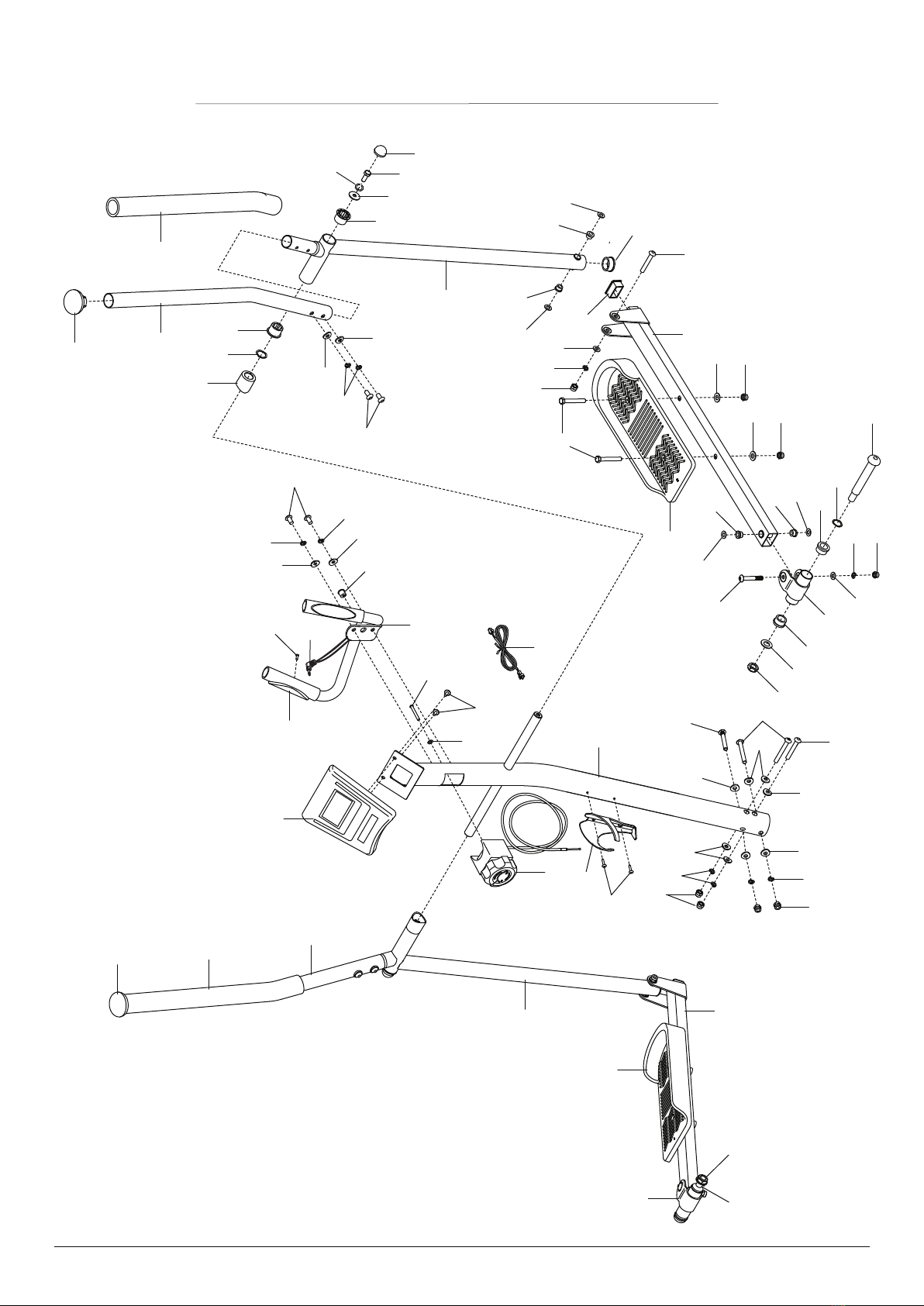
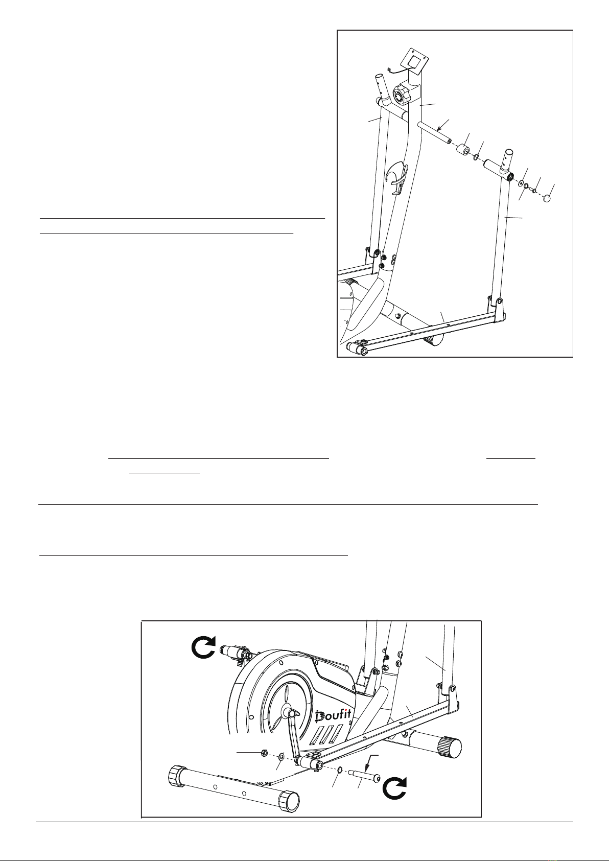
Exploded Diagram(A)---------------------------------------------------------------------------------------------- - - -
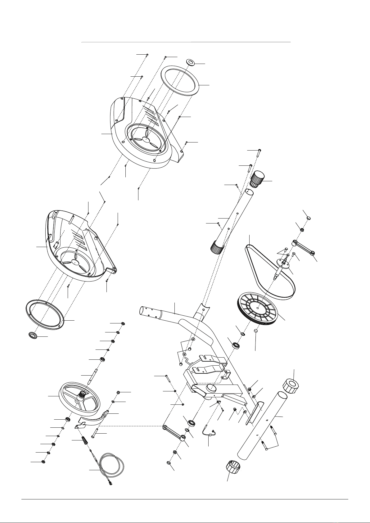
Exploded Diagram(B)---------------------------------------------------------------------------------------------- - - -
Parts List ----------------------------------------------------------------------------------------------------------- - - - -
Accessories Chart-------------------------------------------------------------------------------------------------- - - - -
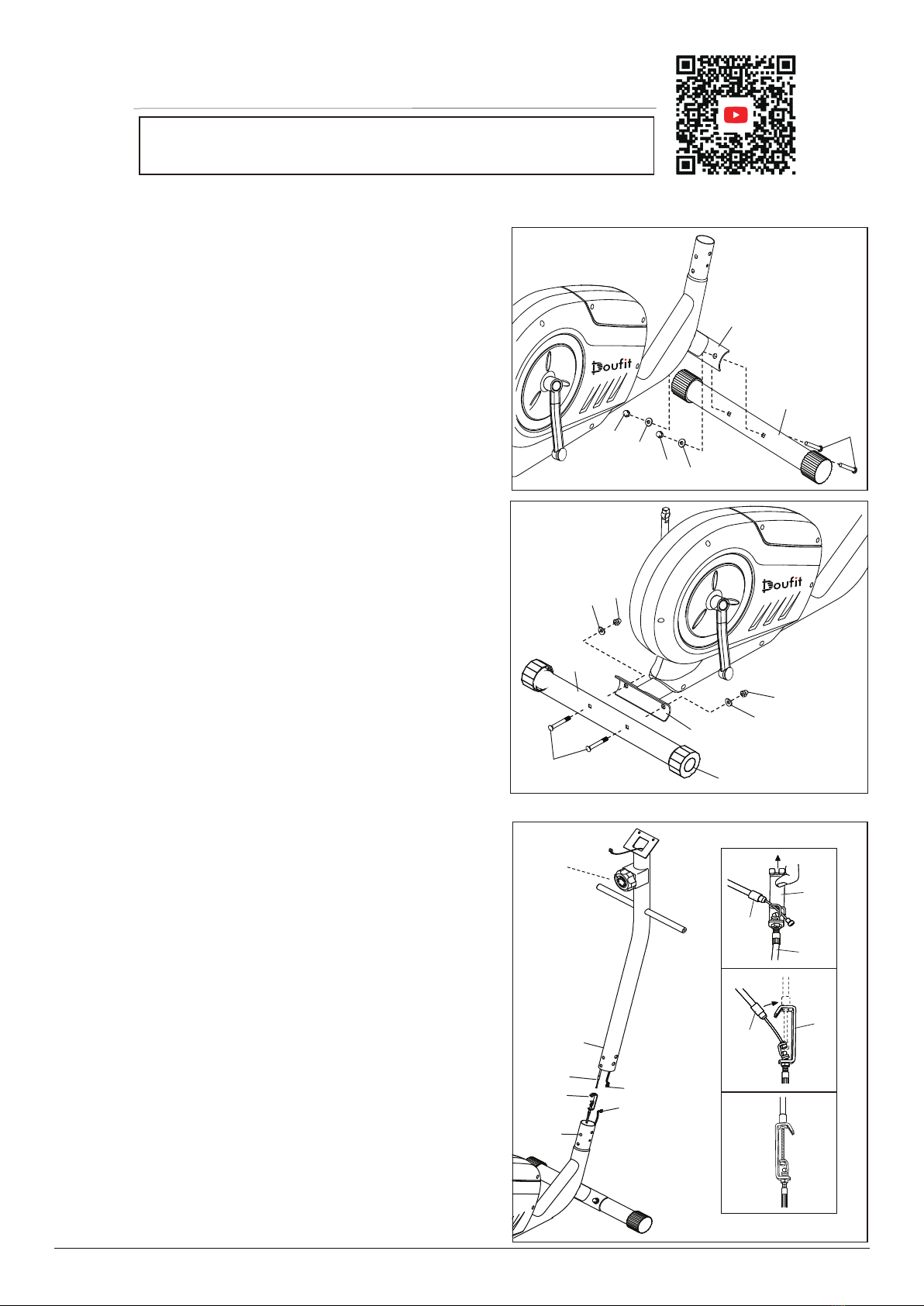
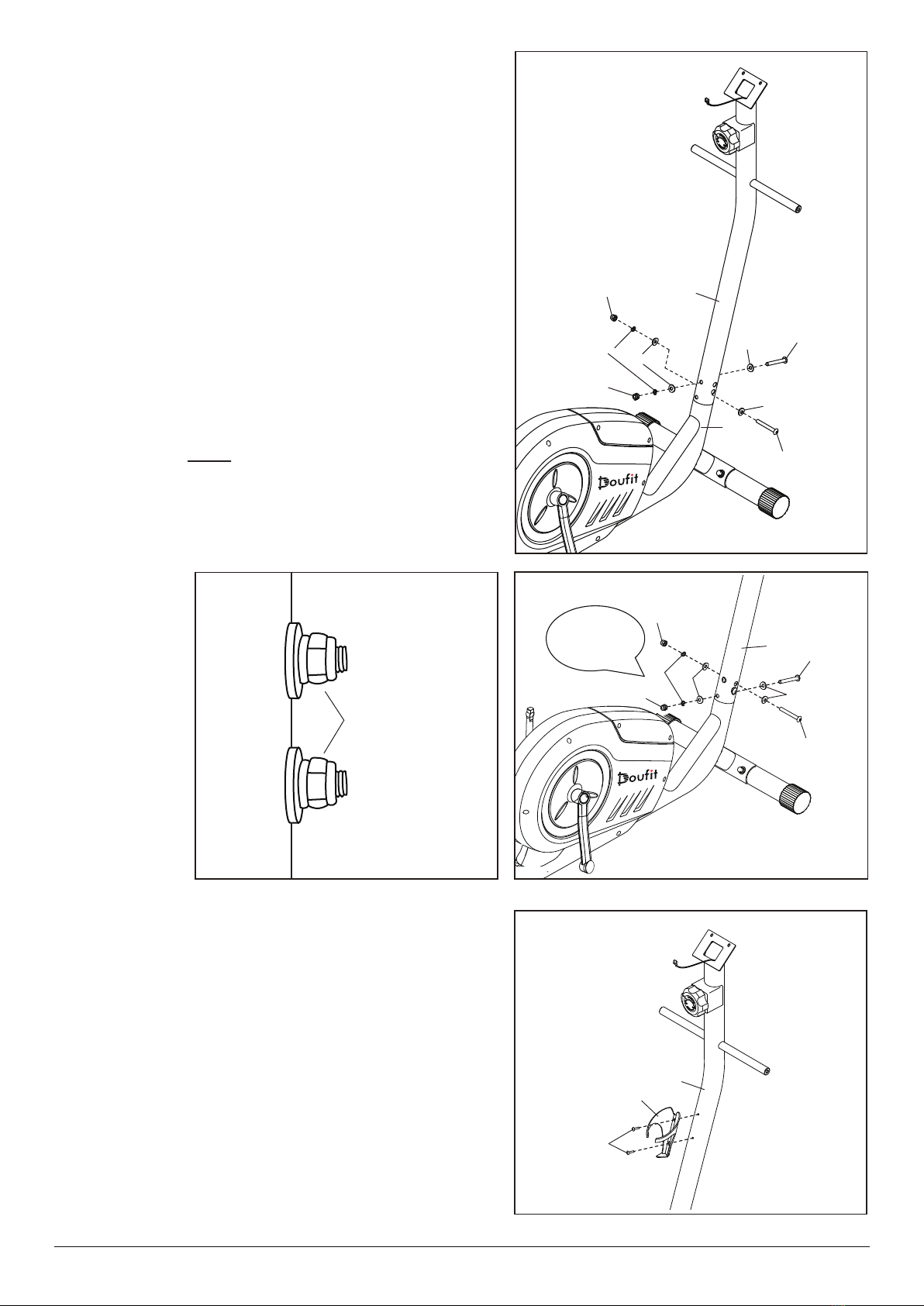
Assembly Method-------------------------------------------------------------------------------------------------- - - - -
Details of Monitor------------------------------------------------------------------------------------------------- - - - -
Precautions
*The maximum load bearing is 114 Kg (250 Lbs).
*Don’t use this product without your physician's approval.
*Frequent strenuous exercise must be approved by your doctor. Please exercise in moderation according
to your physical condition.
*If you feel unwell during using the product, please stop using it immediately and consult your doctor
for instructions before next use.
*Please read the instruction manual carefully before assembly.
*During use, must keep children away from the machine.
*For children, elderly or disable people, they can only use it under guardianship.
*For your safety, you must keep at least 1 meter away from anything around.
*Always check if all of the screws and bolts are tightened. And regularly check all of moving parts for
obvious signs of wear or damage.
*Clean it with a wet cloth. Solvent cleaners are prohibited.
*Please place the product on a flat and solid place to avoid falling. If necessary, use a rubber mat
underneath to avoid slipping.
*It is better to wear proper sportswear during exercise. Don’t wear the clothes too loose to avoid drag.
*Keep it in a clean and dry place to avoid rusting and other problems we can control.
*Before using, please warm up at first. Ride lightly, adjust your breath and pace to slowly get into
motion.
*Regular exercise with relevant nutritious diet is more effective for your fitness.
*Don’t use the product immediately after diet or drinking, you need to wait for at least 1 hour.
Page 1
1
2
3
4
5
6
11
Possible Problems & Relevant Solutions------------------------------------------------------------------------------ 12
Service ------------------------------------------------------------------------------------------------------------- - ---- 12