Doughboy Stair Waves 0-5700-236 Operating and maintenance manual

Stair Waves
Pool Entry System
Model: 0-5700-236
Staircase System for 48” & 52” Tall Pools
Owner's Guide and Warranty
365-1881

SAFETY PRECAUTIONS
READ AND FOLLOW ALL INSTRUCTIONS
Failure to follow important safety instructions and
precautions may result in serious personal injury.
1. The Stair Waves Entry System must be installed in
accordance with these instructions.
2. NEVER JUMP OR DIVE from the platform or stairs. The
StairWaves Entry System is for sitting, standing, and entering
or exiting the pool only.
3. Always install the staircase cover and secure it with the
padlock provided when the pool is unattended.
4. Keep the Stair Waves Entry System free of pool toys or
debris that people could trip over causing personal injury.
5. Always use the handrails when enteringor exitingthe pool.
6. CAUTION: Never install the stairs on a sloping uneven
pool bottomthatcouldresult intiltedor rocking steps. Uneven,
unbalanced footing may lead to personal injury.
7. DANGER! ELECTRICAL HAZARD. Use extreme
caution when using an electric drill when near water. Never
useanelectricdrillwhenstandingin ortouchingwater. Always
use a cordless drill when working in or near water.
8. Some pools may not have the necessary strength to support
theunit by the top rails alone. When possible, INSTALLTHE
STAIRS OVER A VERTICAL SUPPORT.
PREPARATIONS
The Stair Waves Entry System may be installed at any point
around the pool that provides a flat surface for mounting the
platform. See PRECAUTIONS above. Chose a location that
will be convenient for entering and exiting the pool and
provides adequate clearance.
Clearances
You will need an clearance area 58” deep x 43” wide outside
the pool for the staircase. See Fig. 1.
Tools Required
You will need the following tools for installation:
• Flat-bladed Screwdriver
• Phillips Screwdriver
• 7/16” Wrench
• Drill
• 1/8”, 5/32”, 7/32”, and 5/16” drill bits
• Pencil
• Drill (cordless type recommended)
Materials Required
To neutralize the steps natural buoyancy, you must weight the
inside pool steps using two (2) or more 8” x 16” x 2” thick
concrete block wall cap stones, or use a similar material of
equal weight.
Before You Begin
Unpack each carton and inventory the parts within against the
parts list on page 7. Be sure that you have all the parts listed
before you begin assembly.
ASSEMBLY
Refer to the illustration below to identify the
hardware used in assembly.
Assemble Inside Stairs
See Fig. 2.
Locate the inside stairs (stairs without safety cover locators),
and turn them upside down (stair treads facing the ground).
Placeapiece of cardboardunderthestairs topreventscratching
ormarring the stairsurfaces. Locate the side panels andinsert
the raised bosses into the recesses on the bottom of the stair
rails as shown. At each boss location, drill a 1/8” diameter
hole through the inside stair rail and one wall of the side panel
2
FIG. 1
HARDWARE

Attach Platform Spacer to Platform
48” Tall Pools OnlySee Fig. 3
Temporarily attach the platform spacer to the underside of
the platform as shown using only two (2) 1/4” x 2-1/8” long
screw and washers. Tighten securely.
Move StairAssembly into Pool
See Fig. 4A
CAUTION: Always enlist the aid of at least one other
person when moving and lifting large components.
Move the inside stair assembly as near as possible to the
selected installation location. Carefully lift the assembly and
rest it on the pool’s top rails over a vertical support location.
CAUTION: The stair assembly may be to heavy for some
top rails to support. To avoid damaging the top rails,
always rest the stair’s weight over a vertical support
location for additional support.
Lift the stair assemblyinto the pool being careful not tocontact
and/or damage the pool liner with the handrail ends if they
are already installed (see NOTE above). Turn the assembly
upright as shown and position it near the selected installation
location.
Filled Pools: Tilt the stairs so that trapped air can escape
through the small predrilled vent holes.
boss. Be careful not to drill completely through both sides
of the stair rails. Secure each side panel to the stairs using
three (3) #10 x 1-1/2” long screws.
Locate the spacer pipe and insert each end into a side panel
hole as shown. Drill a 1/8” diameter hole into the pipe using
the predrilled hole in the side panel as a guide. Fasten the
spacer pipe to the side panels using two (2) #10 x 1/2” screws.
Complete the assembly by tightening all screws securely.
Turntheassemblyupright. Locate two(2) handrails andattach
them to the inside stairs using four (4) 1/4” x 1-3/4” long
screws. Tighten securely.
NOTE: If your pool is not filled with water, moving the
stair assembly into the pool will be easier if you attach the
handrails after the stairs are inside the pool.
3
FIG. 2
FIG. 3

4
Install Concrete Blocks
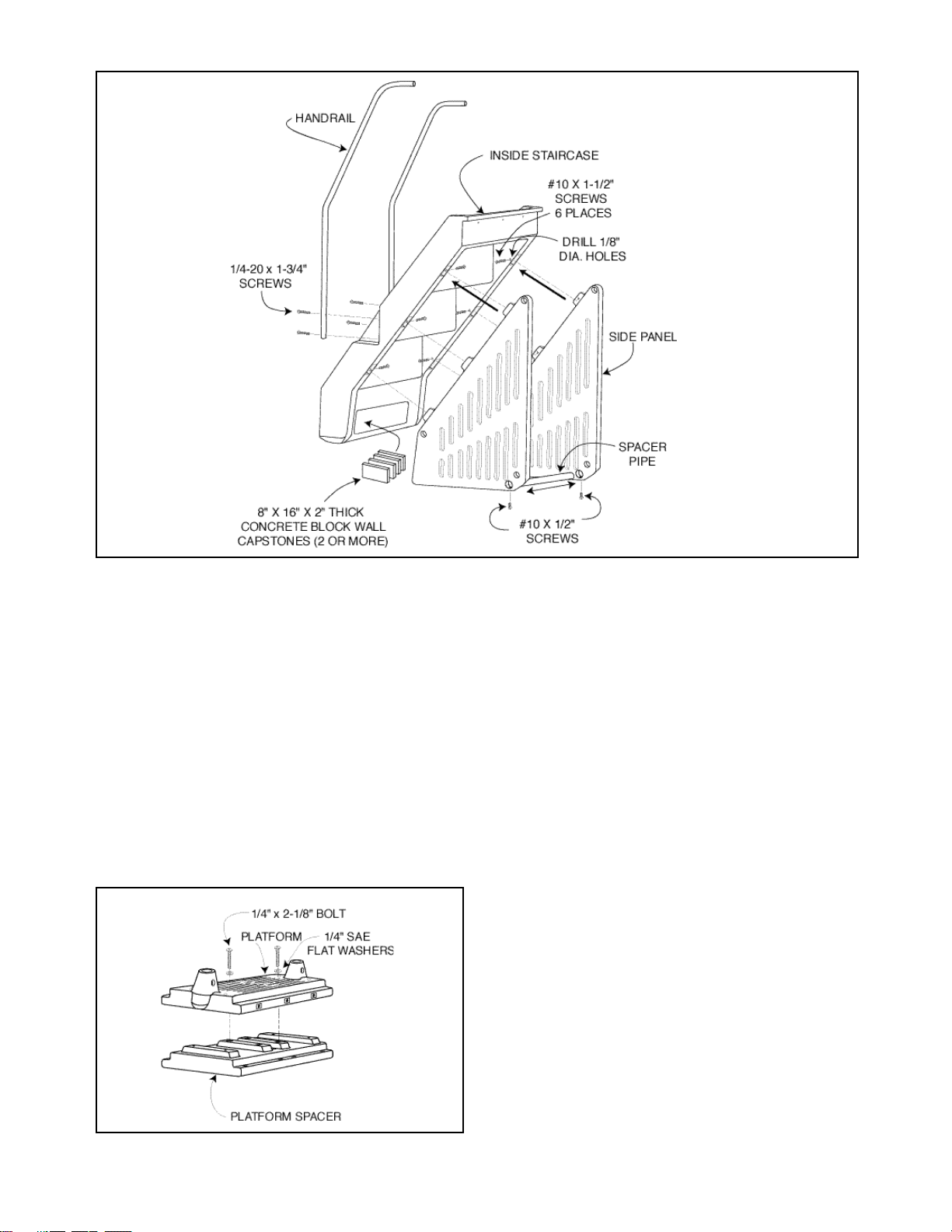
See Fig. 2
You must insert two (2) or more 8” x 16” x 2” thick concrete
block wall capstones into the stair cavity as shown in Fig. 2.
The blocks counteract the stairs natural buoyancy and will
help to stabilize the completed assembly. CAUTION: Don’t
install the blocks until the stair assembly is in the pool.
The blocks could fall out causing damage to the pool or
cause personal injury. When installing bocks when the
pool is filled, be sure that you have someone to assist you.
Remove Top Connector
Remove the pool’s top connector from the area selected for
platform installation so the platform can lay flat on the pool’s
top rails. DO NOTREMOVESCREWSTHATATTACHTHE
TOP RAILS TO THE VERTICAL END CAP.
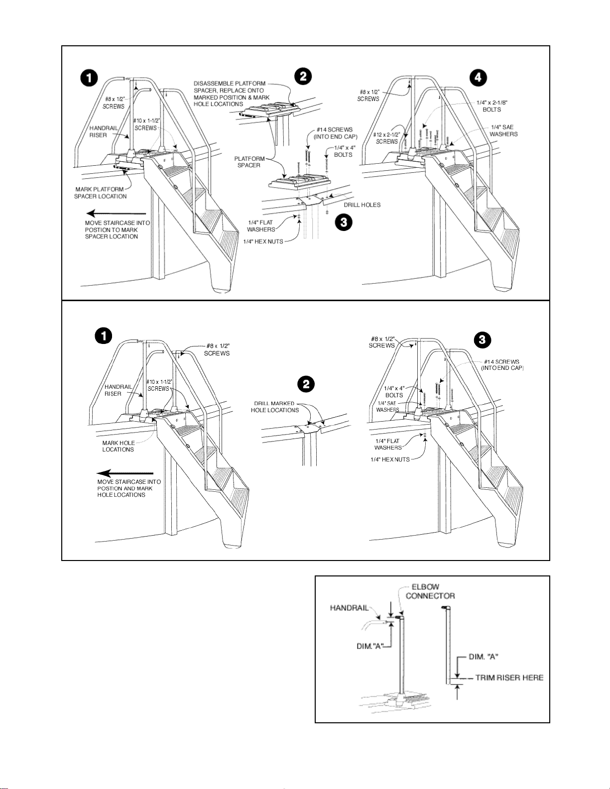
Locate and Drill Mounting Holes
See Fig. 4A for 52” Tall Pools
See Fig. 4B for 48” Tall Pools
Move the inside stair assembly to the selected installation
location and position it completely against the pool wall at
its final location.
Lay the platform (52” Pools) or platform with spacer (48”
Pools) attached onto the top rails and align its threaded brass
holes with the holes in top edge of the staircase. Install three
(3) 1/4” x 1” long screws with 1/4” flat washers through
staircase holes into the platform. Tighten securely.
Recheck the staircase and platform position in relation to the
pool wall and make any final adjustments to its location Be
sure that both side panels are as tight as possible against
the pool wall.
IMPORTANT: For additional strength, it is recommended
that you install at least two #14 sheet metal screws into the
FIG. 4
vertical end cap. If possible, locate hole positions where bolts
and nuts will be on the outside of the pool wall. Avoid hole
locations where the drill bit could contact and damage the
pool wall or liner.
52” Pools Only (See Fig. 4A): When satisfied with the
platform’s position, select the holes you will use for fastening
the platform to the pool’s frame. For maximum stability, you
should connect the platform to the pool frame in at least four
places. Use a pencil to mark hole locations through the
platform onto the top rails and vertical end cap.
After marking holes, move the staircase/platform assembly
aside and drill 5/16” diameter holes at the marked locations
on the top rails. Drill 7/32” diameter holes for connection to
vertical end caps with #14 x 3-1/2” screws.
48” Pools Only (See Fig. 4B): When satisfied with the
platform’s position, use a pencil to mark the platform spacer’s
location onto the top rails. Move the staircase aside and
disassemble the spacer from the platform. Return the spacer
to the position previously marked and select the holes you
will use for fastening the platform spacer to the pool’s frame.
For maximumstability,youshouldconnectthe platformspacer
to the pool frame in at least four places. Use a pencil to mark
hole locations through thespaceronto the top rails and vertical
end cap.
After marking holes, move the platform spacer aside and drill
5/16” diameter holes at the marked locations on the top rails.
Drill 7/32” diameter holes for connection to vertical end caps
with #14 x 3-1/2” screws.
AttachInsideStaircaseAssemblyToPoolFrame
48” Pools only - See Fig. 5:
Fasten the platform spacer to the pool frame using 1/4 x 4”
long bolts, washers, and nuts. Use #14 x 3-1/2” screws with
washers when fastening to the vertical end cap.

5
FIG. 5 - 48” Tall Pools
FIG. 6 - 52” Tall Pools
Movethestaircase assemblybackintopositionandreassemble
the platform to the platform spacer using four (4) 1/4 x
2-1/8” long screws and washers at the central locations. Drill
four (4) 1/8” dia. holes at the four corner locations and install
four (4) #12 x 2-1/2” screws
52” Pools only - See Fig. 6: Move the staircase assembly into
position and fasten the platform to the pool frame using 1/4 x
4” long bolts, washers, and nuts. Use #14 x 3-1/2” screws
with washers when fastening to the vertical end cap.
Trim Handrail Risers
See Fig. 7
The handrail risers are sized to fit a variety of installation
conditions. Locate the handrail risers and insert them into the
FIG. 7
OUTSIDE OF POOL OUTSIDE OF POOL

platform sockets. Turn them so that the connector tees at the
top are pointing to and aligned with the handrails ends.
Observe the position of the handrail tubes to the connector
tees. If the risers are too long or short, follow the instructions
below. If they are the correct height when resting in the their
sockets, proceed directly to Install Handrail Risers.
If the connector tees are too high for the handrails to make a
straight, levelconnection, you will needto cutthe excess tubing
from the BOTTOM of the riser tube. Measure the distance
(Dim. “A”) from the center of handrail tube to the centerline
ofthe connectortee. MarkthedistanceDim.“A”onthebottom
end of the riser tube and remove the excess tubing with a
hacksaw or other suitable tool.
If the connector tees are too low, raise the riser tube to the
level of the handrail ends. Use a small piece of wood under
the riser tube to shim it up to the correct height.
Install Handrail Risers
See Figs. 5 or 6
With the risers at the correct height in the platform socket and
aligned withthe handrails,drilla 5/32” holethroughthebottom
of the each riser tube (1 side only) using the predrilled holes
in the platform sockets as guides. Secure each riser tube to its
socket using one (1) #10 x 1-1/2” screw.
Connect Inside Handrails to Connector Tees
See Figs. 5 or 6
Pushthe handrail ends over the connector tees and secure each
of them using a #8 x 1/2” long screw.
Attach Outside Staircase to Platform
See Figs. 5 or 6.
Position the outside staircase on the platform flange and align
thestaircasemountingholeswith thematchingplatformholes.
Remove or add soil or stepping stones under the staircase
bottom step as needed to achieve a level position. Secure the
assembly by installing three (3) 1/4” x 1” screws and 1/4”
washers.
Connect Outside Handrails
See Fig. 8
Attach the two remaining handrails to the outside staircase
using four (4) 1/4-20 x 1-3/4” long screws. Tighten securely.
Pushthe handrail ends over the connector tees and secure each
of them using a #8 x 1/2” long screw.
6
FIG. 8
FIG. 9
Install Padlock Hasp
See Fig. 9
Positionthepadlock haspover thethreadedholesintheoutside
staircase rail. Fasten the hasp to the rail using two (2) 1/4 x
1/2” long screws. Note: The turned-up flange should be
toward the outside of the rail.
INSTALLING SAFETY COVER
See EXPLODED ASSEMBLY page 7.
Position the safety cover over the stairs as shown on page 7.
Lower thecover’s squarecutoutsover theraisedcoverlocators
n the staircase. While holding the cover’s cutouts tightly
against the stair’s left rail, slide the cover toward the padlock
hasp (edges of cutouts sliding under cover locators) until the
cover’s right cutout settles over the padlock hasp. To secure
the safety cover, use the padlock provided.
REPAIR & MAINTENANCE
Contact your local Doughboy dealer for original replacement
parts. Retain this owner’s guide for reference when ordering
parts or making a warranty claim.
Periodically inspect the Stair Waves Entry System to detect
looseormissinghardware. Tightenallloosescrewsandalways
replace any that are missing.
CLEANING
Clean your Stair Waves Entry System with mild detergent and
water only. NEVER USE SOLVENTS OR ABRASIVE
CLEANERS TO CLEAN THE STAIR WAVES ENTRY
SYSTEM.

7
ITEM # PART NO. QTY. DESCRIPTION
0-5700-193 1 Stair Pack
1. 349-1027 1 Outside Stairs
2. 349-1048 1 Inside Stairs
3. 349-1039 2 Side Panel
4. 349-1029 1 Safety Cover
0-5700-194 1 Hand Rail Pack
5. 330-1172 2 #10 X 1/2” Screw
6. 341-1394 1 Side Panel Spacer Pipe
7. 330-1279 8 1/4-20 x 1-3/4” Phillips Head Mach. Screw
8. 580-2077 4 Handrail
9. 330-1008 4 #8 x 1/2” Screw
10. 330-1151 6 1/4-20 x 1” Truss Head Mach. Screw
11. 580-2086 2 Handrail Riser
12. 330-1025 2 #12 x 1-1/8” Screw
13. 340-2267 2 Connector Tee
14. 349-1031 1 Platform
15. 330-1229 4 1/4-20 x 4” Phillips Head Mach. Screw
16. 321-1021 4 1/4-20 Hex Nut
17. 327-1051 4 1/4” x 3/4” O.D. Flat Washer
18. 330-1282 2 #14 x 3-1/2” Screw
19. 510-1001 8 #10 x 1-1/2” Screw
20. 426-1000 18 1/4” SAE Flat Washer
21. 330-1225 4 1/4-20 x 2-1/8” Phillips Head Mach. Screw
22. 330-1286 4 #12 x 2-1/2” Pan Head Screw
23. 349-1033 1 Platform Spacer
24. 385-1419 1 Padlock Hasp
25. 330-1072 2 1/4-20 x 1/2” Truss Head Mach. Screw
26. 332-1064 1 Padlock
27. 365-1881 1 Owner’s Guide & Warranty
Stair Waves Entry System
Model 0-5700-236
EXPLODEDASSEMBLY SAFETY
COVER
COVER
LOCATORS
8” X 16” X 2” THICK
CONCRETE BLOCK
WALL CAPSTONES
(NOT PROVIDED)

StairWaves Pool Entry System
FIVEYEAR
LIMITED WARRANTY
TERMS AND CONDITIONS
Retain this warranty along with your sales receipt and/or proof of purchase.
1. Doughboy is the warrantor of this product.
2. This warranty is extended to the original purchaser (consumer) only.
3. Doughboy warrants the Stair Waves Pool Entry System for a period of five (5) years from date of purchase
against all defects in materials and workmanship.
4. The Stair Waves is warranted for a period of five (5) years from date of purchase against all defects in materi-
als and workmanship.
To exercise this warranty, the consumer must return the Stair Waves unit to the dealer where it was
purchased.
5. The Stair Waves unit will be repaired or replaced promptly after your pool dealer determines that
there is a defect in materials or workmanship.
The method of proration on this warranty is to repair or replace free of charge any part(s) found defective in
the first three (3) years from the date of purchase. For the next two (2) years part(s) found to have
manufacturing defects will be replaced at a prorated cost equal to the following percentages of the then
existing manufacturer’s suggested retail prices.
The percentages below are paid by the consumer and apply at the beginning of the year listed:
Years 1-3 0%
Years 4-5 65%
6. This warranty is null and void if the design of this product is altered in any way. Thus, the product
must be assembled according to the factory directions and no changes or modifications may be made
to any of the parts.
7. Damage from chemical misuse or ice damage is not covered under warranty.
8. This warranty gives specific legal rights; the purchaser also has implied warranty rights which may vary from
state to state.
Terms of sale of our warranty exclude liability for willful carelessness.
DOUGHBOY RECREATIONAL • 10959 Jersey Blvd. • Rancho Cucamonga, CA 91730
Visit our website at www.doughboy-pools.com
DB 1101-001 Made in the United States of America Copyright © 2001
Changeof Design: DoughboyRecreationalexpresslyreservestherighttochangeormodifythedesignandconstruction
ofanyproductinduecourseofourmanufacturingprocedures,withoutincurringanyobligationorliabilitytofurnishorinstall
such changes or modifications on products previously or subsequently sold.
Table of contents
Other Doughboy Lighting Equipment manuals