Doughboy Stair Waves Operating and maintenance manual

365-2020
Pool Entry System
In Pool Deck Stairs
Owner's Guide andWarranty

SAFETYPRECAUTIONS
READ AND FOLLOW ALL INSTRUCTIONS
Failure to followimportant safety instructions and
precautions may result in serious personal injury.
1. The Stair Entry System must be installed in accordance
with these instructions.
2. NEVER JUMP OR DIVE from the platform or steps. The
Stair Entry System is for sitting, standing, and entering or
exiting the pool only.
3. Keep the Stair Entry System free of pool toys and other
objects or debris that people could trip over causing personal
injury.
4. Alwaysusethe handrailswhen enteringorexitingthe pool.
5. CAUTION: Never install the stairs on a sloping uneven
pool bottomthatcouldresultintiltedorrockingsteps. Uneven,
unbalanced footing may lead to personal injury.
6. DANGER! ELECTRICAL HAZARD. Use extreme
caution when using an electric drill when near water. Never
useanelectricdrillwhenstandinginortouchingwater. Always
use a cordless drill when working in or near water.
PREPARATIONS
See Fig. 1
The Stair Entry System may be installed at any point around
the pool frame that provides a solid flat surface for mounting
theplatform.The in-poolstairsmust reston aflat levelpool
floor. See SAFETY PRECAUTIONS above.
To prevent unauthorized access to your pool, select a position
on your pool that can be viewed from all directions.
SELECT LADDER LOCATION
See Fig. 2
Locate the stairs for convenient access to and from the pool.
Avoid locating the stairs adjacent to an outside deck ladder or
stairway traffic.
Tools Required
You will need the following tools for installation:
• Flat-bladed Screwdriver
• Phillips Screwdriver
• Hacksaw
• Drill (cordless type recommended)
• Drill bits - 1/8’ for spacer pipe & side panels holes,
5/32” for riser holes, 5/16” for 1/4” bolts.
• Pencil
Materials Required
To neutralize the steps natural buoyancy, you must weight
down the pool steps using two (2) or more 8” x 16” x 2” thick
concrete block wall capstones, or use a similar material of
equal weight.
Before You Begin
Unpack each carton and inventory the parts within against the
parts list on page 5. Be sure that you have all the parts listed
before you beginassembly. Report any missing parts to your
pool dealer for prompt replacement.
Hardware
Refer to the illustration below to identify the hardware used
for assembly.
2
FIG. 1
FIG. 2
HARDWARE

Turntheassemblyupright. Locatetwo(2)handrailsandattach
them to the stairs using four (4) 1/4” x 1-3/4” long screws.
Tighten securely.
NOTE: If your pool is not filled with water, moving the
stair assembly into the pool will be easier if you attach the
handrails after the stairs are inside the pool.
Attach Platform Spacer to Platform
48” Tall Pools Only - See Fig. 4
Temporarily attach the platform spacer to the underside of
the platform as shown using only two (2) 1/4” x 2-1/8” long
screw and washers. Tighten securely.
Move Stair Assembly into Pool
CAUTION: Always enlist the aid of at least one other
person when moving and lifting large components.
Move the stair assembly as near as possible to the selected
installation location. Carefully lift the assembly and rest it on
the pool’s top rails and/or deck.
CAUTION: The stair assembly may be to heavy forsome
top rails to support. To avoid damage to pool top rails,
always rest the stair’s weight on thedeck or over a vertical
support location for additional support.
Assemble Stairs
See Fig. 3.
Locatethestairs,andturnthemupsidedown(stairtreadsfacing
the ground). Place a piece of cardboard under the stairs to
prevent scratching or marring the stair surfaces. Locate the
side panels and insert the raised bosses into the recesses on
the bottom of the stair rails as shown. At each boss location,
drill a 1/8” diameter hole through the inside stair rail and one
wallofthesidepanelboss. Becarefulnottodrillcompletely
through both sidesof the stair rails. Secure each side panel
to the stairs using three (3) #10 x 1-1/2” long screws.
Locate the spacer pipe and insert each end into a side panel
hole as shown. Drill a 1/8” diameter hole into the pipe using
the predrilled hole in the side panel as a guide. Fasten the
spacer pipe tothe side panelsusing two(2) #10x 1/2”screws.
Complete the assembly by tightening all screws securely.
3
FIG. 3 FIG. 4
FIG. 5A - 52” TALL POOLS

Lift the stair assembly into the pool being careful not to
contact and/or damage the pool liner with the handrail ends
if they are already installed (see NOTE above). Turn the
assembly upright as shown and position it near the selected
installation location.
Filled Pools: Tilt the stairs so that trapped air can escape
through the small predrilled vent holes.
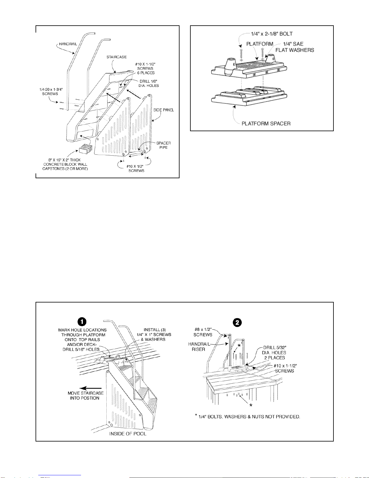
Install Concrete Blocks
See Fig. 3
You must insert two (2) or more 8” x 16” x 2” thick concrete
block wallcapstones into the stair cavity as shown in Fig. 3.
The blocks counteract the stairs natural buoyancy and will
helptostabilizethecompletedassembly. CAUTION: Don’t
install the blocks until the stair assembly is in the pool.
Theblockscouldfalloutcausingdamagetothepooland/
or deck or cause personal injury. When installing blocks
when the pool is filled, be sure that you have someone to
assist you.
Remove Top Connector (If required)
Iftheplatformistobelocatedovera verticalsupport,remove
the pool’s top connector from the area selected for platform
installationsotheplatformcan layflat on thepool’stoprails.
DO NOT REMOVE SCREWS THAT ATTACH THE TOP
RAILS TO THE VERTICAL END CAP.
Locate and Drill Mounting Holes
See Fig. 5A for 52” Tall Pools
See Fig. 5B for 48” Tall Pools
Move the inside stair assembly to the selected installation
location and position it completely against the pool wall at
its final location.
Lay the platform (52” Pools) or platform with spacer (48”
Pools)attached ontothe top rails andalign itsthreaded brass
holes with the holes intop edge of the staircase. Install three
(3) 1/4” x 1” long screws with 1/4” flat washers through
staircase holes into the platform. Tighten securely.
Recheck the staircase and platform position in relation to
the pool wall andmake any final adjustmentsto its location
Be sure that both side panels are as tight as possible
against the pool wall.
IMPORTANT: Foradditional strength,it isrecommended
that you install at least two #14 sheet metal screws into the
vertical endcap when the platform is locatedovera vertical
support. If possible, locate hole positions where bolts and
nuts will be on the outside of the pool wall. Avoid hole
locations where the drill bit could contact and damage
the pool wall or liner.
52” Pools Only (See Fig. 5A): When satisfied with the
platform’sposition,selecttheholesyouwilluseforfastening
the platform to the pool’s frame. For maximum stability,
youshouldconnectthe platformtothe poolframe in at least
four places. Use a pencil to mark hole locations through
the platform onto the top rails and vertical end cap.
After marking holes, move the staircase/platform assembly
aside anddrill 5/16” diameterholes at the marked locations
on the top rails. Drill 7/32” diameter holes for connection
to vertical end caps with #14 x 3-1/2” screws.
48” Pools Only (See Fig. 5B): When satisfied with the
platform’s position, use a pencil to mark the platform
spacer’slocationonto thetoprails. Movethestaircaseaside
and disassemble the spacer from the platform. Return the
spacer totheposition previouslymarked andselectthe holes
you will use for fastening the platform spacer to the pool’s
frame. For maximum stability, you should connect the
platform spacer to the pool frame in at least four places.
Use a pencil to mark hole locationsthrough the spacer onto
the top rails and vertical end cap.
After marking holes, move the platform spacer aside and
drill 5/16” diameter holes at the marked locations on the
toprails. Drill7/32”diameterholesforconnectiontovertical
end caps with #14 x 3-1/2” screws.
FIG. 5B - 48” TALL POOLS
4

Attach Staircase/Platform Assembly To Pool
Frame
Due to differences in deck construction, fasteners for
securing the platform to your deck are not provided.
However, it is recommended that you use 1/4” diameter
bolts, washers, and nuts for the best results. Lag bolts or
wood screws ARE NOT recommended as they tend to strip
out and loosen over time.
48” Poolsonly - See Fig. 5B: Fasten the platform spacer to
the pool frame using 1/4” bolts, washers, and nuts (not
provided). Use #14 x 3-1/2” screws with washers when
fastening to the vertical end cap. Move the staircase
assembly back into position and reassemble the platform to
the platform spacer using four (4) 1/4 x 2-1/8” long screws
and washersat the central locations. Drill four (4) 1/8” dia.
holes at the four corner locations and install four (4) #12 x
2-1/2” screws
52” Poolsonly - See Fig. 5A: Move the staircase assembly
intopositionand fastenthe platformto the poolframe using
1/4” bolts, washers, and nuts (not provided). Use #14 x 3-
1/2”screwswith washerswhen fasteningtothe vertical end
cap.
Attach Riser Tubes to Platform & Handrails
See Fig. 5A or 5B
With the risers at the correct height and aligned with
handrails ends, drill a 5/32” hole through the bottom of the
each riser tube(1 side only)using thepredrilled holesin the
platform sockets as guides. Secure each riser tube to its
socket using one (1) #10 x 1-1/2” screw. Push the handrail
ends over the connector elbowsand secure them using #8 x
1/2” long screws.
Attach Platform Facing to Platform
48” Tall Pools Only - See Fig. 5B
Fasten theplatform facingto theplatform usingthree (3) 1/4”
screws and washers.
REPAIR & MAINTENANCE
Contactyourlocaldealerfororiginalreplacementparts. Retain
thisowner’sguideforreferencewhenorderingpartsormaking
a warranty claim.
Periodically inspect the Stair Entry System to detect loose or
missinghardware. Tightenallloosescrewsandalwaysreplace
any that are missing.
CLEANING
Clean your Stair Entry System with mild detergent and water
only. NEVER USE SOLVENTS OR ABRASIVE
CLEANERS TO CLEAN THE STAIR ENTRY SYSTEM.
5

EXPLODEDASSEMBLY
8” X 16” X 2” THICK
CONCRETE BLOCK
WALL CAPSTONES
(NOT PROVIDED)
6
ITEM # PART NO. QTY. DESCRIPTION
*__________ 1 Stair Pack *(write pack number here)
1. 349-1048 1 Inside Stairs
2. 349-1039 2 Side Panel
*__________ 1
Deck Hand Rail Pack
*(write pack number here)
3. 330-1172 2 #10 X 1/2” Screw
4. 341-1394 1 Side Panel Spacer Pipe
5. 330-1279 4 1/4-20 x 1-3/4” Phillips Head Mach. Screw
6. 580-2077 2 Handrail-Deck
7. 330-1008 2 #8 x 1/2” Screw
8. 330-1151 3 1/4-20 x 1” Truss Head Mach. Screw
9. 580-2086 2 Handrail Riser
10. 330-1025 2 #12 x 1-1/8” Screw
11. 340-2268 2 Connector Elbow
12. 349-1031 1 Platform
13. 510-1001 8 #10 x 1-1/2” Screw
14. 426-1000 14 1/4” SAE Flat Washer
15. 349-1033 1 Platform Spacer — 48” pools only
16. 349-1042 1 Platform Facing — 48” pools only
17. 330-1225 8 1/4-20 x 2-1/8” Phillips Head Mach. Screw
18. 330-1286 4 #12 x 2-1/2”Pan Head Screw
19. 365-2020 1 Owner’s Guide & Warranty
In Pool Stair Entry System - Deck
*Model ___________ *(write model number here)

7
In Pool Stair Entry System
FIVEYEAR
LIMITEDWARRANTY
TERMS AND CONDITIONS
Retain this warranty along with your sales receipt and/or proof of purchase.
1. Hoffinger Industries is the warrantor of this product.
2. This warranty is extended to the original purchaser (consumer) only.
3. Hoffinger warrants the Stair Pool Entry System for a period of five (5) years from date of purchase against all
defects in materials and workmanship.
To exercise this warranty, the consumer must return the unit to the dealer where it was purchased.
4. The unit will be repaired or replaced promptly after your pool dealer determines that there is a defect in
materials or workmanship.
The method of proration on this warranty is to repair or replace free of charge any part(s) found defective in
the first three (3) years from the date of purchase. For the next two (2) years part(s) found to have
manufacturing defects will be replaced at a prorated cost equal to the following percentages of the then
existing manufacturer’s suggested retail prices.
The percentages below are paid by the consumer and apply at the beginning of the year listed:
Years 1-3 0%
Years 4-5 65%
5. This warranty is null and void if the design of this product is altered in any way. Thus, the product
must be assembled according to the factory directions and no changes or modifications may be made
to any of the parts.
6. Damage from chemical misuse or ice damage is not covered under warranty.
7. This warranty gives specific legal rights; the purchaser also has implied warranty rights which may vary from
state to state.
Terms of sale of our warranty exclude liability for willful carelessness.

HOFFINGER INDUSTRIES • 315 N. Sebastian St. • West Helena, AR 72390
DB 1007-400 Made in the United States of America Copyright © 2008
ChangeofDesign: HoffingerIndustriesexpresslyreservestherighttochangeormodifythedesignandconstruction
of any product in due course of our manufacturing procedures, without incurring any obligation or liability to furnish
or install such changes or modifications on products previously or subsequently sold.
Table of contents
Other Doughboy Lighting Equipment manuals