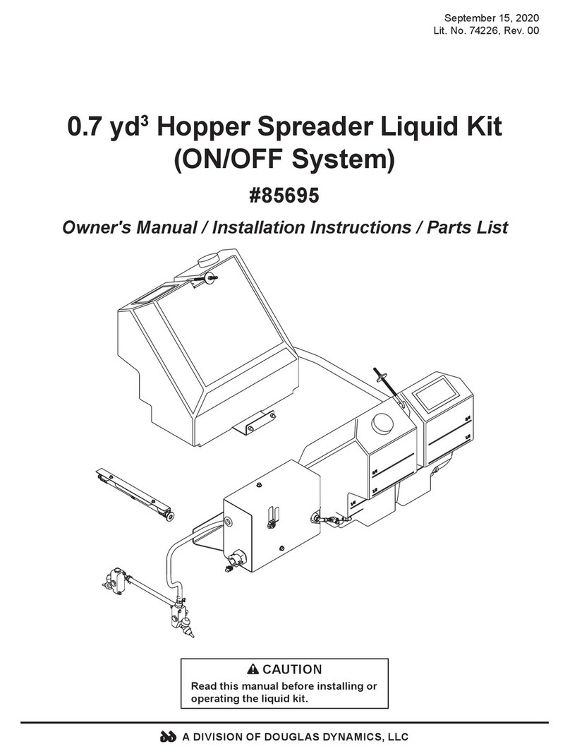
Douglas Dynamics 85689 User manual

September 15, 2020
Lit. No. 74171, Rev. 00
HELIXX™ 0.7 yd3Hopper Spreader
Liquid Kit
(ON/OFF System)
#85689
Owner's Manual / Installation Instructions / Parts List
CAUTION
Read this manual before installing or
operating the liquid kit.
A DIVISION OF DOUGLAS DYNAMICS, LLC

Lit. No. 74171, Rev. 00 2 September 15, 2020

Lit. No. 74171, Rev. 00 3 September 15, 2020
TABLE OF CONTENTS
SAFETY ..................................................................... 4
Safety Definitions .................................................. 4
Warning/Caution Labels ....................................... 4
Safety Precautions................................................ 5
Personal Safety..................................................... 5
Cell Phones........................................................... 6
Ventilation ............................................................. 6
Battery Safety ....................................................... 6
Noise..................................................................... 6
Vibration................................................................ 6
Torque Chart ......................................................... 6
MOUNTING THE PUMP BOX .................................. 7
MOUNTING SPRAY BRACKET, SPRAY
MANIFOLDS & NOZZLES .................................... 8
Mounting the Spray Bracket.................................. 8
Mounting Manifolds & Nozzles ............................. 8
MOUNTING THE TANKS ......................................... 9
Mounting the Tanks............................................... 9
Installing the Tank Mounting Brackets .................. 9
INSTALLING TANKS & STRAPS.......................... 10
PLUMBING THE SYSTEM ..................................... 11
Plumbing the Output Side................................... 11
Plumbing the Input Side...................................... 11
WIRING & HARNESS INSTALLATION ............... 13
Installing the Pump Kit ........................................ 13
Liquid Kit Harness Wiring Diagram..................... 14
OPERATING INSTRUCTIONS ............................. 16
Application Rates................................................ 16
MAINTENANCE & TROUBLESHOOTING........... 19
Periodic Maintenance ......................................... 19
Cleaning.............................................................. 19
End of Season and Storage................................ 19
Troubleshooting Guide........................................ 19
PARTS LIST ............................................................ 20
Pump Box Components ......................................20
Spray System Components ................................22
Tank Components............................................... 24
Internal Pump Box Components......................... 26
Electrical Components........................................ 27

Lit. No. 74171, Rev. 00 4 September 15, 2020
SAFETY DEFINITIONS
NOTE: Indicates a situation or action that can lead
to damage to your liquid system and vehicle or
other property. Other useful information can also
be described.
SAFETY
WARNING/CAUTION LABELS
Please become familiar with the warning and caution
labels on the liquid system.
NOTE: If labels are missing or cannot be read, see
your sales outlet.
CAUTION
Indicates a potentially hazardous situation
that, if not avoided, may result in minor or
moderate injury. It may also be used to alert
against unsafe practices.
WARNING
Indicates a potentially hazardous situation
that, if not avoided, could result in death or
serious personal injury.
Warning Label – Corrosivity Hazard
Warning/Caution Label

Lit. No. 74171, Rev. 00 5 September 15, 2020
SAFETY
SAFETY PRECAUTIONS
Improper installation and operation could cause
personal injury and/or equipment and property
damage. Read and understand labels and the
Owner's Manual before installing, operating, or making
adjustments.
WARNING
• Driver to keep bystanders a minimum of
25 feet away from operating liquid system.
• Before working with the liquid system,
secure all loose-fitting clothing and
unrestrained hair.
• Before operating the liquid system, verify
that all safety guards are in place.
• Before servicing the liquid system, wait for
conveyor and spinner to stop.
• Do not climb into or ride on liquid system.
WARNING
• The drive shafts, conveyor, and spinner
assemblies transmit great amounts of
power and, accordingly, are hazardous
when in operation. All maintenance,
inspections, or operator adjustments must
be made with all source power OFF.
• Keep liquid system and surrounding area
clear of personnel and property when
operating.
• When traveling, especially fully loaded, this
machine may have a high center of gravity,
and care should be exercised when turning
or driving on banked surfaces.
• Unauthorized modifications to the liquid
system and related components may impair
the function and/or safety.
CAUTION
• Do not operate a liquid system in need of
maintenance.
• Before operating the liquid system,
reassemble any parts or hardware removed
for cleaning or adjusting.
• Before operating the liquid system, remove
materials such as cleaning rags, brushes,
and hand tools from the liquid system.
• While operating the liquid system, use
auxiliary warning lights, except when
prohibited by law.
• Tighten all fasteners according to the
torque chart. Refer to torque chart for the
recommended torque values.
CAUTION
Disconnect electric and/or hydraulic power
and tag out if required before servicing or
performing maintenance.
PERSONAL SAFETY
• Remove the ignition key and put the vehicle in
PARK or in gear to prevent others from starting
the vehicle during installation or service.
• Wear only snug-fitting clothing while working on
your vehicle or liquid system.
• Do not wear jewelry or a necktie, and secure long
hair.
• Wear safety goggles to protect your eyes from
battery acid, gasoline, dirt, dust, and brine.
• Avoid touching hot surfaces such as the engine,
radiator, hoses, and exhaust pipes.
• Always have a fire extinguisher rated BC handy,
for flammable liquids and electrical fires.
CAUTION
DO NOT leave unused material in hopper.
Material can freeze or solidify, causing unit to
not work properly. Empty and clean after each
use.
WARNING
Overloading could result in an accident or
damage. Do not exceed GVWR or GAWR
ratings as found on the driver-side door
cornerpost of the vehicle. See Loading
section of your spreader Owner's Manual to
determine maximum volumes of spreading
material.
Lit. No. 74171, Rev. 00 6 September 15, 2020
CELL PHONES
A driver's first responsibility is the safe operation of
the vehicle. The most important thing you can do
to prevent a crash is to avoid distractions and pay
attention to the road. Wait until it is safe to operate
mobile communication equipment such as cell phones,
text messaging devices, pagers, or two-way radios.
VENTILATION
BATTERY SAFETY
NOISE
Airborne noise emission during use is below 70 dB(A)
for the liquid system operator.
VIBRATION
Operating liquid system vibration does not exceed
2.5 m/s2to the hand-arm or 0.5 m/s2to the whole body.
SAFETY
TORQUE CHART
1/4-20 109 154
1/4-28 121 171
5/16-18 150 212
5/16-24 170 240
3/8-16 269 376
3/8-24 297 420
7/16-14 429 606
7/16 -20
9/16-12
9/16-18
5/8-11
5/8-18
3/4-10
3/4-16
7/8-9
7/8-14 474 669
644 9091-8
1-12 704 995
1/2-13
1/2-20
11.9
13.7
24.6
27.3
43.6
26.9
53.3
93
148
49.4
69.8
77.9
106.4
120.0
8.4
9.7
17.4
19.2
30.8
35.0
49.4
55.2
75.3
85.0
M6 x 1.00
M12 x 1.75
M8 x 1.25
M14 x 2.00
M10 x 1.50
M27 x 3.00
M22 x 2.50
M30 x 3.50
M24 x 3.00
M20 x 2.5011.1
19.5
38.5
67
107
7.7
613
778
1139
1545
450
428
562
796
1117
M33 x 3.50
M36 x 4.00
2101
2701
1468
1952
325
M16 x 2.00 231
167
M18 x 2.50 318222
Recommended Fastener Torque Chart
Size Size
Torque (ft- lb)
Grade
5
Grade
8
Metric Fasteners Class 8.8 and 10.9
These torque values apply to fasteners
except those noted in the instructions.
Torque (ft- lb)
Grade
5
Grade
8
Size Size
Torque (ft- lb)
Class
8.8
Class
10.9
Torque (ft- lb)
Class
8.8
Class
10.9
Inch Fasteners Grade 5 and Grade 8
CAUTION
Batteries normally produce explosive gases
which can cause personal injury. Therefore,
do not allow flames, sparks, or lit tobacco
to come near the battery. When charging or
working near a battery, always cover your
face and protect your eyes, and also provide
ventilation.
• Batteries contain sulfuric acid which burns
skin, eyes, and clothing.
• Disconnect the battery before removing or
replacing any electrical components.
CAUTION
Read instructions before assembling. Fasteners
should be finger tight until instructed to tighten
according to torque chart. Use standard
methods and practices when attaching liquid
system, including proper personal protective
safety equipment.
WARNING
Vehicle exhaust contains lethal fumes. Breathing
these fumes, even in low concentrations,
can cause death. Never operate a vehicle in
an enclosed area without venting exhaust to
the outside.

Lit. No. 74171, Rev. 00 7 September 15, 2020
3. Fasten the pump box mount bracket to the pump
box using four 3/8" flanged cap screws.
4. From the passenger's side of the spreader, find the
two 3/8" flanged cap screws that fasten the extension
cover to the auger. Remove the 3/8" flanged cap
screw that is closest to the hopper body.
5. Position the pump box bracket as shown in the
diagram. Using two 3/8" flanged cap screws and
3/8" locknuts, fasten the pump box bracket to the
rear support flange. Reinstall 3/8" flanged cap
screw that was removed in Step 4.
MOUNTING THE PUMP BOX
1. Remove all packing material from the liquid kit
before installation.
2. Remove the chute and trough extension cover
with electrical box.
MOUNTING THE PUMP BOX
Chute
Electrical
Box
Trough
Extension
Cover
Auger Extension Cover
3/8" Flanged
Cap
Screw
3/8" Flanged
Cap Screws
Pump
Box
Pump Box
Mount Bracket
3/8" Flanged
Cap Screws

Lit. No. 74171, Rev. 00 8 September 15, 2020
MOUNTING MANIFOLDS & NOZZLES
1. Position a manifold assembly with fittings to each
side of the chute frame and align the mounting
holes.
NOTE: The driver-side manifold top port is
plugged. The passenger-side manifold top port
has a 1/2" straight barb fitting.
2. Install the assembly using a 1/4" x 2" cap screw
in the top hole and a 1/4" x 1-1/2" cap screw in
the bottom hole. Secure the cap screws with
1/4" locknuts.
3. Connect the manifolds with a 14" long length of
1/2" tubing between the 90° elbow fittings. Secure
the tubing with spring-type clamps.
Plug in
Top Port
of Driver-Side
Manifold
Spring-Type
Clamp
1/2" x 14"
Tubing
1/4"
Locknuts
1/4" x 2"
Cap Screw
1/4" x 1-1/2"
Cap Screw
1/2" Straight
Barb Fitting in
Top Port of
Passenger-Side
Manifold
MOUNTING SPRAY BRACKET, SPRAY MANIFOLDS & NOZZLES
MOUNTING THE SPRAY BRACKET
1. Remove the knockout on the passenger's side
of the sill extension cover and install a hose
grommet.
2. Use three loop clamps and 1/4" x 3/4" serrated
flange cap screws with 1/4" locknuts to attach the
spray hose to the spray bar. Verify that the slits in
the spray hose face the auger when installed. The
slits will be along the pink line.
3. Use two 1/4" x 3/4" serrated flange cap screws
with 1/4" locknuts to fasten the spray bar assembly
to the sill extension cover as shown.
4. Connect the spray bar hose to the hose that exits
through the rear face of the pump box. Position
the spring clamps at each end of the hose.
1/4" Locknut
1/4"
Locknut
1/4" x 3/4"
Serrated Flange
Cap Screws
1/4" x 3/4"
Serrated Flange
Cap Screws
Spray Hose
Spray
Bar
Loop
Clamp
Sill
Extension
Cover
1/4" Locknuts
1/4"
Locknut
1/4" x 3/4"
Serrated Flange
Cap Screws
Spray Hose
Spray
Bar
Loop
Clamp

Lit. No. 74171, Rev. 00 9 September 15, 2020
MOUNTING THE TANKS
INSTALLING THE TANK MOUNTING
BRACKETS
Position the tank tray as shown below and secure
each tank mounting bracket with four 3/8" flanged cap
screws and 3/8" locknuts.
MOUNTING THE TANKS
NOTE: While handling the hopper, ensure that the
hopper mounting bolts do not damage the liquid
tanks.
If this is a new hopper spreader installation,
follow the installation steps as outlined in the hopper
spreader Installation Instructions. Once the spreader
has been located in the vehicle and the mounting
holes have been made, remove the spreader from
the vehicle. Ensure that the mounting bolts are in the
mounting bar holes before installing the liquid tanks
to the hopper spreader.
If this hopper spreader has been previously
installed in the vehicle, remove the hopper from
the vehicle. Ensure that the mounting bolts are in the
mounting bar holes before installing the liquid tanks to
the hopper spreader.
Once the tanks have been installed onto the hopper
spreader, place the spreader back into the vehicle,
and mount it to the vehicle as described in the hopper
spreader Installation Instructions.
3/8" Flanged
Cap Screws 3/8"
Locknuts
Tank Mounting
Bracket

Lit. No. 74171, Rev. 00 10 September 15, 2020
INSTALLING TANKS & STRAPS
1. Use the stainless steel 3/8" flanged cap screws
and 3/8" locknuts to install the tank trays to the
tank bracket.
2. Insert a 3/8" x 1" carriage bolt into the tank tray so
that the button head is facing the tank.
3. Place the tank on the tank tray. Verify that the
recess in the bottom of the tank is seated into the
tray.
4. Use the 3/8" x 1" carriage bolt and 3/8" hardware
to install the tank support strap.
5. Loop the 3/8" x 8" J-bolt through the tank support
strap and insert it through the knockout hole in the
hopper body. Loop the J-bolt so that the hook is
facing upward.
3/8" Flanged
Cap Screws
3/8"
Locknuts
3/8"
Locknut
Tank
Support
Strap
Tank
Tray
J-Bolt
Tank
Bracket
6. For the J-bolt, place one 2" fender washer and
locknut on the inside of the hopper with the
locknut facing toward the auger. Tighten the nut
toward the hopper body.
NOTE: Do not use power tools to tighten the
J-bolts; use hand tools only. Overtightening can
cause galling of the stainless steel threads.
7. Cut the excess bolt length from the J-bolt if
desired.
8. Repeat Steps 1–7 for the remaining tank.
NOTE: If installing the 100-gallon expansion kit,
install the brackets and tanks in the same fashion.

Lit. No. 74171, Rev. 00 11 September 15, 2020
PLUMBING THE INPUT SIDE
1. Use the 1/2" ID hose to connect the strainer inlet
elbow to the closest tank using a 1/2" barb elbow
fitting.
2. Cut the hose and install the tank shutoffvalve in a
suitable location.
Secure all connections using hose clamps.
• 1/2" Hoses: Use spring-type clamps.
• 1" Hoses: Use stainless band clamps.
Use the provided pipe sealant on all NPT fittings.
PLUMBING THE OUTPUT SIDE
1. Connect a 1/2" hose to the 1/2" barb fitting on top of
the passenger-side manifold. Secure with a clamp.
2. Cut the hose to a suitable length to reach the
quick coupler on the pump box. Install the cam
lever coupler (male end) and connect it to the
pump box. Hose length must be sufficient to
permit rotating the chute up to the dump position.
PLUMBING THE SYSTEM
1/2" Barb Fitting on Manifold
1/2" ID Hose
Cam Level Coupler (male end)
Tank Shutoff Valve Tank Bulkhead
w/Elbow

Lit. No. 74171, Rev. 00 12 September 15, 2020
PLUMBING THE SYSTEM
3. To connect additional tanks, install a 1" barb elbow
into the bulkhead and use a 1" hose to connect the
tanks in series. Install the 3/4" plug in the final tank.
4. At the front of the spreader, remove two of
the 3/8" flange head cap screws. Secure the
1" hose to the front plate using 1" band clamps
and mounting the hose over the holes left by the
screws. Place the removed screws back in place
with the hose clamps on them.
1" Hose
and Elbow Fittings
5. Verify that all bulkhead fittings are tightened to
20 ft-lb.
6. Install the drive cover, routing the 1/2" hose to the
manifold outside the cover and under the hose
bracket.

Lit. No. 74171, Rev. 00 13 September 15, 2020
WIRING & HARNESS INSTALLATION
INSTALLING THE PUMP KIT
NOTE: The liquid accessory harness kit provides
an ON/OFF switch to activate the
liquid system from inside the vehicle.
To properly wire the ON/OFF pump kit, follow these
instructions and refer to the Liquid Kit Harness Wiring
Diagram on page 14.
1. Install the ON/OFF pump kit.
2. Remove the chute from the spreader.
3. Remove the cover from the hopper electrical
enclosure located on the top of the trough extension.
4. Find the break-thru plug on the passenger's side
of the electrical enclosure and use a tool to cut an
"X" in the center of the plug. Route the liquid kit
relay assembly harness through the cut break-thru
plug. Use cable ties to attach the liquid kit relay
assembly harness to the motor cable.
CAUTION
Before drilling any holes, check both sides
of the material for any wires, fuel lines, fuel
tanks, etc., that may be damaged by drilling.
5. Route the harness along the hopper to the pump
enclosure. On the pump enclosure, take out one
of the break-thru plugs. Route the liquid kit relay
assembly harness out of the pump box through
the hole left by the break-thru plug. Seal the
hole with a grommet. Route the harness to the
electrical enclosure along the hopper.
6. Remove the cover from the isolated stud block.
7. Attach the ring terminal connected to the red
wire of the liquid kit harness to the POSITIVE (+)
terminal of the isolated stud block.
8. Attach the ring terminal connected to the black
wire of the liquid kit harness to the NEGATIVE (–)
terminal of the isolated stud block.
9. Connect the male bullet terminal of the liquid kit
wire assembly harness to the orange wire coming
from the spreader module.
10. Reinstall the covers onto the isolated stud block
and electrical enclosure.
11. Secure all harnessing to prevent damage to the
wires.
Isolated Stud Block
Spreader
Module
Break-Thru Plugs

Lit. No. 74171, Rev. 00 14 September 15, 2020
WIRING & HARNESS INSTALLATION
LIQUID KIT HARNESS WIRING DIAGRAM
Red & Black from
Spreader Module or
Accessory Harness
to Acc Power Block
Orange wire from Spreader
Module or Accessory Switch
PUMP BOX
PRE-WET RELAY ASSEMBLY
RED
BLK
ORN
RED
BLK
ACC POWER BLOCK
RED
BLK
PUMP
MOTOR
30A Mini Fuse
35A Micro Relay

Lit. No. 74171, Rev. 00 15 September 15, 2020
OPERATING INSTRUCTIONS
ADJUSTING THE FLOW
To adjust the flow between direct application on the
chute and direct application to the material, rotate the
valve on the front of the pump box.
The following table shows the flow rates for the
ON/OFF system. These values are approximate
and can vary based on system configuration, age of
components, brine composition, and other factors.
The flow of the system is controlled by a needle valve
inside the pump box. Follow the instructions below to
adjust the flow.
1. Remove the pump box cover.
2. Turn the white plastic handle to the left of the
pump. Clockwise will reduce the flow and
counter-clockwise will increase the flow.
NOTE: Do not overtighten the handle.
Overtightening may damage the valve.
3. With the pump running, turn the valve clockwise
until the flow stops. This is the "zero flow" point.
Do not turn the valve further.
4. Mark the valve handle and body to indicate the
"zero flow" point for future reference.
5. Turn the valve counter-clockwise a number of
complete turns as indicated by the "ON/OFF Flow
Rates" table below.
ON/OFF Flow Rates
Number of Turns from
Zero Flow Position gal/min
00
1/4 0.22
1/2 0.46
3/4 0.66
10.80
21.13
31.40
3-1/2+ 1.60
No Valve 2.00
NOTE: If higher flow rates are required, bypass
the needle valve to increase the flow. Refer to
Bypassing the Needle Valve.
BYPASSING THE NEEDLE VALVE
1. Remove the needle valve and install the 1/2" hose
barb directly into the street elbow.
2. Replace the hose with the 1/2" hose kit. The new
flow rate will be approximately 2.63 gal/min.
MANUALLY CALIBRATING THE FLOW
To obtain a more precise measurement of the flow
rate, follow the steps below.
1. Adjust the liquid system to the desired setting.
2. Disconnect the 1/2" hose connected to the spray
hose and place it in a 5-gallon bucket.
3. Turn on the liquid system and time how long
it takes (in seconds) for the system to fill the
5-gallon bucket.
4. Determine the flow in gal/min by dividing 300 by
the results from Step 3 (in seconds).
Example:
It took 165 seconds to fill the bucket.
300 = 1.82 gal/min
165

Lit. No. 74171, Rev. 00 16 September 15, 2020
APPLICATION RATE
The following application chart shows the approximate material delivery rate for HELIXX™ hopper spreaders.
Use these charts to determine the auger delivery rate of de-icing salt, which is based on the auger speed.
12345678
0.00
1.00
2.00
3.00
4.00
Auger Flow Rate (ft³/min)
Auger Speed Control Setting
HELIXX Hopper Spreaders
OPERATING INSTRUCTIONS

Lit. No. 74171, Rev. 00 17 September 15, 2020
OPERATING INSTRUCTIONS
After the auger delivery rate has been determined, use the following table to determine the optimal flow rate for
the liquid system.
NOTE: This value may vary depending on de-icing chemicals used and weather conditions. Consult
the material manufacturer's recommended application rates. Gallons per ton refers to the amount of
pre-wetting agent applied per ton of de-icing salt.
Gallons per Ton
Delivery Flow Rate
(ft³/min) 681012
0.5 0.11 0.15 0.19 0. 2 2
1 0.22 0.30 0.37 0.44
1.5 0.33 0.44 0.56 0.67
20.440.590.740.89
2.5 0.56 0.74 0.93 1.11
30.670.891.111.33
3.5 0.78 1.04 1.30 1.56
40.891.191.481.78
4.5 1.00 1.33 1.67 2.00
51.111.481.852.22
5.5 1.22 1.63 2.04 2.44
61.331.782.222.67
7 1.56 2.07 2.59 –
81.782.37––
92.002.67––
10 2.22–––
11 2.44–––
12 2.67–––
Optimal Flow Rate

Lit. No. 74171, Rev. 00 18 September 15, 2020
4. Find the point at which these two values meet on
the table (see example below). This box shows
the Optimal Flow Rate for this liquid application
(0.74 gal/min).
5. To achieve the desired liquid rate in this example,
you would adjust the system to 0.74 gal/min. For
details, refer to "Adjusting the Flow" on page 15.
Material Application Example:
A HELIXX™ hopper spreader is running at auger
speed 7. The desired liquid rate is 8 gallons per ton.
Use the following procedure to determine the optimal
flow rate in gal/min.
1. On the Application Rate chart on page 16, find
the point on the graph where the 7 on the Auger
Speed axis and the line intersect.
2. Follow from the point of intersection across to
the Auger Flow Rate axis, as shown below. The
delivery flow rate for this example is 2.5 ft³/min.
3. On the Optimal Flow Rate table on page 17,
find the Delivery Flow Rate value (previously
determined in Step 2 (2.5 ft³/min) and the
Application Rate (8 gal/ton).
OPERATING INSTRUCTIONS
Gallons per Ton
Delivery Flow Rate
(ft³/min) 681012
0.5 0.11 0.15 0.19 0. 22
1 0.22 0.30 0.37 0.44
1.5 0.33 0.44 0.56 0.67
20.440.590.740.89
2.5 0.56 0.74 0.93 1.11
30.670.891.111.33
3.5 0.78 1.04 1.30 1.56
40.891.191.481.78
4.5 1.00 1.33 1.67 2.00
12345678
0.00
1.00
2.00
3.00
4.00
Auger Flow Rate (ft³/min)
Auger Speed Control Setting
HELIXX Hopper Spreaders
2.5
ft3/min

Lit. No. 74171, Rev. 00 19 September 15, 2020
MAINTENANCE & TROUBLESHOOTING
PERIODIC MAINTENANCE
• Wash unit after each use to prevent material
build-up and corrosion.
• Use dielectric grease on all electrical connections
to prevent corrosion each time power or signal
plugs are disconnected.
• Inspect unit for damage, such as broken, worn, or
bent parts.
• Inspect all tubing, hoses, and harnesses for
cracks and leaks.
• Clean the brine filter as needed. Close the shut-off
valve and access the filter by unscrewing the top
cap, then unscrewing the filter cover.
• Retighten bolts, screws, and other connections
after first use and as needed.
CLEANING
• Clean the unit as desired. When pressure
washing motor enclosure area, keep spray at least
36" away from motor enclosures.
• Use caution if you are flushing the pumping
system with water as it will accumulate in the
valves and can cause damage if the water inside
freezes. Use antifreeze if unit is to be stored in
freezing temperatures.
END OF SEASON AND STORAGE
• Before long periods of storage, flush out the tanks
and pumping system to remove salt build-up and
prevent corrosion.
• Do not leave unused material in the unit for a
prolonged period of time.
TROUBLESHOOTING GUIDE
Problem Possible Cause Suggested Solution
Pump is not operating.
1. Loose electrical connection. 1. Check all electrical connections for
corrosion.
2. Blown fuse. 2. Replace the fuse.
3. Pump seized. 3. Replace the pump.
Control shut down.
1. Loose electrical connection. 1. Check all electrical connections for
corrosion.
2. Electrical short. 2. Check for bare or burned wires.
3. Control failure. 3. Replace the control.
4. Blown fuse. 4. Replace the fuse.
Material being spread is not wet.
1. Liquid system is not running. 1. See Troubleshooting – Pump is not
operating.
2. Spray hose is misaligned. 2. See "Mounting the Spray Bracket" on
page 8.
3. Flow rate is set too low. 3. See "Adjusting the Flow" on
page 15.
Spray is uneven. 1. Spray hose is clogged. 1. Clean spray hose with fresh water.
2. Spray hose is damaged. 2. Replace the spray hose.
Pump is leaking.
1. O-ring fittings are loose. 1. Verify that O-ring fittings are fully
installed.
2. O-rings are damaged or worn. 2. Replace the O-rings.
3. Pump housing is damaged. 3. Replace the pump.

Lit. No. 74171, Rev. 00 20 September 15, 2020
PARTS LIST
PUMP BOX COMPONENTS
9
6
5
4
3
1
7
Cover not shown.
14
15
13
12
8
11
11
10
9
18
19
20
21
22
23
24
25
26
2
16
17
9
This manual suits for next models
3
Table of contents
Other Douglas Dynamics Spreader manuals

Douglas Dynamics
Douglas Dynamics SnowEx HELIXX Series User manual

Douglas Dynamics
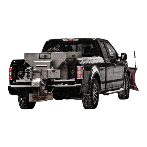
Douglas Dynamics Western Plows 85695 User manual

Douglas Dynamics
Douglas Dynamics Western Striker 98805 User manual

Douglas Dynamics
Douglas Dynamics SnowEx HELIXX 1.5 yd3 User manual

Douglas Dynamics
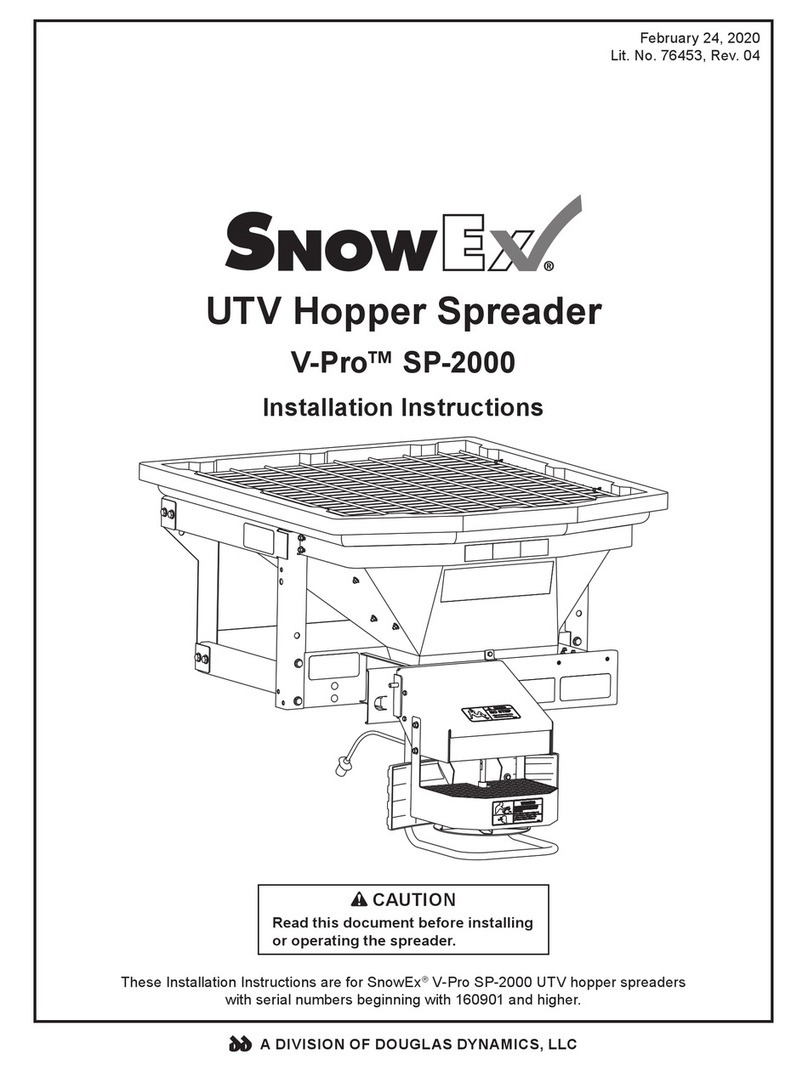
Douglas Dynamics SnowEx V-Pro SP-2000 User manual