Dover Unified Brands Groen HyperSteam HY-6G User manual

This manual provides information for:
OPERATOR MANUAL
IMPORTANT INFORMATION, KEEP FOR OPERATOR
PART NUMBER 128805 REV G (07/14)
MODEL HY-6G(CE)
HYPERSTEAM™
ATMOSPHERIC
CONVECTION STEAMER
INTERNATIONAL
· Self Contained
· Gas
· Capacity: 6 Steamer Pans (12” x 20” x 2-1/2”)
.ECNEREFERERUTUFROFDENIATEREBTSUMLAUNAMSIHT
READ, UNDERSTAND AND FOLLOW THE INSTRUCTIONS AND
WARNINGS CONTAINED IN THIS MANUAL.
WARNING / FOR YOUR SAFETY
and liquids in the vicinity of this or any other appliance.
POST IN A PROMINENT LOCATION
Instructions to be followed in the event user smells
gas. This information shall be obtained by consulting
your local gas supplier. As a minimum, turn off the gas
and call your gas company and your authorized service
agent. Evacuate all personnel from the area.
WARNING
Improper installation, adjustment, alteration, service
or maintenance can cause property damage, injury or
death. Read the installation, operating and maintenance
instructions thoroughly before installing or servicing this
equipment.
NOTIFY CARRIER OF DAMAGE AT ONCE
It is the responsibility of the consignee to inspect the container upon receipt of
same and to determine the possibility of any damage, including concealed dam-
age. Unified Brands suggests that if you are suspicious of damage to make a
notation on the delivery receipt. It will be the responsibility of the consignee to file
a claim with the carrier. We recommend that you do so at once.
Manufacture Service/Questions 888-994-7636.
Information contained in this document is known to be current and accurate at the time
of printing/creation. Unified Brands recommends referencing our product line websites,
unifiedbrands.net, for the most updated product information and specifications.
1055 Mendell Davis Drive
Jackson, MS 39272
888-994-7636, fax 888-864-7636
unifiedbrands.net

2 OM-HY/6G(CE)
IMPORTANT - READ FIRST - IMPORTANT
IT IS MOST IMPORTANT THAT THESE INSTRUCTIONS AND THE OPERATOR AND SERVICE MANUALS BE
CONSULTED BEFORE INSTALLING AND COMMISSIONING THE APPLIANCE. FAILURE TO COMPLY WITH SPECIFIED
PROCEDURES MAY RESULT IN DAMAGE OR THE NEED FOR A SERVICE CALL.
THESE APPLIANCES HAVE BEEN CE MARKED ON THE BASIS OF COMPLIANCE WITH THE GAS APPLIANCE
DIRECTIVE, EMC AND LOW VOLTAGE DIRECTIVE FOR THE COUNTRIES, GAS TYPES AND PRESSURES AS STATED
ON THE DATA PLATE.
THESE APPLIANCES MUST BE INSTALLED BY A COMPETENT PERSON IN CONFORMITY WITH THE INSTALLATION
AND SERVICING INSTRUCTIONS AND NATIONAL REGULATIONS IN FORCE AT THE TIME. PARTICULAR ATTENTION
MUST BE PAID TO THE FOLLOWING:
I. E. E. REGULATIONS FOR ELECTRICAL INSTALLATIONS
ELECTRICITY AT WORK REGULATIONS
GAS SAFETY (INSTALLATION AND USE) REGULATIONS
HEALTH AND SAFETY AT WORK ACT
LOCAL AND NATIONAL BUILDING REGULATIONS
FIRE PRECAUTIONS ACT
DETAILED RECOMMENDATIONS ARE CONTAINED IN INSTITUTE OF GAS ENGINEERS PUBLISHED DOCUMENTS:
IGE/UP/1, IGE/UP/2, BS6173 AND BE5440.
FURTHERMORE, IS A NEED ARISES TO CONVERT THE APPLIANCE FOR USE WITH ANOTHER GAS, A COMPETENT
PERSON MUST BE CONSULTED. THOSE PARTS WHICH HAVE BEEN PROTECTED BY THE MANUFACTURER MUST
NOT BE ADJUSTED BY THE USER.
USERS SHOULD BE CONVERSANT WITH THE APPROPRIATE PROVISIONS OF THE FIRE PRECAUTIONS ACT AND
THE REQUIREMENTS OF THE GAS SAFETY REGULATIONS. IN PARTICULAR THEY SHOULD BE AWARE OF THE
NEED FOR REGULAR SERVICING BY A COMPETENT PERSON TO ENSURE THE CONTINUED SAFE AND EFFICIENT
PERFORMANCE OF THE APPLIANCE.
WARNING: TO PREVENT SHOCKS, ALL APPLIANCES GAS OR ELECTRIC, MUST BE EARTHED.
UPON COMPLETION OF THE INSTALLATION, THE OWNERS MANUAL SHOULD BE HANDED TO THE USERS
AND THE INSTALLER SHOULD INSTRUCT THE RESPONSIBLE PERSON(S) IN THE CORRECT OPERATION AND
MAINTENANCE OF THE APPLIANCE.
THIS EQUIPMENT IS ONLY FOR PROFESSIONAL USE, AND SHALL BE OPERATED BY QUALIFIED PERSONS. IT
IS THE RESPONSIBILITY OF THE SUPERVISOR OR EQUIVALENT TO ENSURE THAT USERS WEAR SUITABLE
PROTECTIVE CLOTHING AND TO DRAW ATTENTION TO THE FACT THAT, SOME PARTS WILL, BY NECESSITY,
BECOME VERY HOT AND WILL CAUSE BURNS IF TOUCHED ACCIDENTALLY.
WARNING: BEFORE REMOVING ANY PARTITION OR PANEL, ALWAYS TURN OFF THE ELECTRIC POWER AND
ALLOW THE FAN TO STOP ROTATING. BEFORE WORKING ON ANY ELECTRICAL COMPONENT,
DISCONNECT THE POWER SOURCE FROM THE UNIT.
NOTE: IT IS IMPORTANT THAT THE END-USER ROUTINELY EXAMINE THE FLUE OUTLET ON A REGULAR
BASIS. DEBRIS COVERING THE FLUE OUTLET CAN CAUSE A POTENTIALLY HAZARDOUS
CONDITION. REMOVE ANY FOREIGN MATERIAL BEFORE USING THIS PIECE OF EQUIPMENT.
WARNINGS AND CAUTIONS PROVIDED IN THE BASIC OPERATOR AND SERVICE MANUALS (OM-HY-6G
AND GROEN HYPERSTEAM SERVICE MANUAL) MUST BE COMPLIED WITH.

OM-HY/6G(CE) 3
Important Operator Warnings ........................................................ page 2
References.................................................................................... page 3
Equipment Description.................................................................. page 4
Water Quality and Treatment .......................................................... page 5
Inspection and Unpacking ............................................................ page 6
Installation .................................................................................. page 7-9
Initial Start-Up......................................................................... page 10-11
Operation ............................................................................... page 12-13
Cleaning.................................................................................. page 14-15
Maintenance................................................................................. page 16
Troubleshooting............................................................................ page 17
Electrical Schematic .................................................................. page 25
Service Procedures ............................................................... page 26-39
Service Log ................................................................................. page 40
UNDERWRITERS LABORATORIES, INC.
333 Pngsten Road
Northbrook, Illinois 60062
KLENZADE SALES CENTER
ECOLAB, Inc.
370 Wabasha
St. Paul, Minnesota 55102
800 328-3663 or 612 293-2233
NATIONAL FIRE PROTECTION ASSOCIATION
60 Batterymarch Park
Quincy, Massachusetts 02269
NFPA/70 The National Electrical Code
NSF INTERNATIONAL
789 N. Dixboro Rd.
P.O. Box 130140
Ann Arbor, Michigan 48113
Table of Contents
References

4 OM-HY/6G(CE)
Your Groen HY-6G (CE) HyPerSteam Convection Steamer is designed to give years of
service. It has two stainless steel cavities (cooking chambers) which are served by
twin, independent atmospheric steam generators which are gas-heated. A powerful
blower circulates the steam in each cavity to increase heating efficiency.
Each cavity holds up to three steam table pans (305 x 508 x 64 mm). A 1.5 mm
stainless steel case encloses the cavities, the steam generators and the control
compartment that houses electrical components. Door hinges are reversible (the doors
may be set to open from the left or right). Operating Controls are on the front panel.
HY-6G (CE) steamers are equipped with fully electronic controls and a button-
activated, pre-programmed CLEAN cycle.
The drain system includes a spray condenser, which helps keep steam from escaping
down the condensate drain.
Equipment Description
The HY-6G (CE) has two independent cavities, each
with its own base-mounted steam generator.

OM-HY/6G(CE) 5
Water Quality & Treatment
The BPST Connection on the
right rear side of the steamer.
Treated
Water
Untreated
Water
Drain
REAR VIEW
Gas
Connection
It is essential to supply the steam generator with water that will not form scale or cause
corrosion. Eventhough the steam generator isengineeredto minimize scale formation
and the effects of corrosion, their development depends onthe quality of your water and
the number of hours per day youoperate the equipment.
Most water suppliesare full of minerals and chemicals which are not suitable for use in
a steam generator.
Water quality varies from state to state and city to city. It is necessary that youknow
and understand the quality of the water youare using. Your water utility can tell you
about the minerals and chemicals in your water. The water going to the steam generator
should be within these guidelines
Water Pressure 30-60 psi
PH 7 to 9
Hardness less than 60 ppm
TDS 30 to 60 ppm
Chlorine and Chloramineless than 0.1 ppm
Total Chloride less than 30 ppm
Silica less than 12 ppm
Undissolved Solids less than 5 microns
1. Do not rely on unproven water treatments which are sold for scale prevention or
scale removal. They don’t always work. The best way to prevent scale is to supply
the purest possible water (30 - 60 ppm TDS).
2. If your water contains scale-forming minerals, asmost water does, use a well-main-
tained water softener. Whether anexchangeable softener cartridge or a regenerat-
ing system is chosen, a regular exchange schedule is essential.
3. Installing a water meter betweenthe softener and the steamer will provide an
accurate gauge of water use, and will help determine when to exchange cartridges
or regenerate the softener. Using a water softener will provide longer generator life,
higher steam capacity, and reduce maintenance requirements.
4. If younotice a slowdown in steam production, have the unit checkedfor scale
build-up. Heavy scale reducesthe unit’sability to boil water and can even cause
heating elements inthe steam generator to overheat and burn out.

6 OM-HY/6G(CE)
Inspection & Unpacking
CAUTION
SHIPPING STRAPS ARE UNDER TENSION
AND CAN SNAP BACK WHEN CUT.
Your HY-6G HyPerSteam will be delivered completely assembled in a heavy shipping
carton and attached to a skid. On receipt, inspect the carton carefully for exterior
damage.
Carefully cut the straps around the carton and detach the sides of the carton from the
skid. Be careful to avoid personal injury. Strap edges may be very sharp, particularly
where cut. Write down the model number, serial number and installation date. Space for
these entries is provided in the Service Log at the back of this manual. Keep the manual
near the equipment for reference and update as needed.
When installing, use material handling equipment to lift the unit straight up from the skid.
Check packing materials for any loose parts.
CAUTION
THIS UNIT WEIGHS 550 LBS. (250 KG). GET
HELP AS NEEDED AND USE MATERIAL
HANDLING EQUIPMENT TO MOVE IT.
The unit will be delivered in a heavy
carton, strapped to a wooden skid.

OM-HY/6G(CE) 7
The HY-6G(CE) steamer is suitable for installation in combustible and noncombustible
locations. Minimum clearances for installation are:
Right Side 300 mm (12 inches)
Left Side 0 mm (0 inches)
Rear of Flue 150 mm (6 inches)
However, for easy service at least 300 mm (12 inches) clearance is required for the
right side of the unit, and it may not be installed within 300 mm (12 inches) of a heat
source, as stated in the Caution above.
The unit must be installed in a well-ventilated room with an adequate air supply. The
steamer must be installed beneath a ventilation hood, since gas combustion products
exit the appliance.
Any item which might obstruct or restrict the flow of air for combustion and ventilation
must be removed. Do not obstruct the flue cover or any front, side, rear, or top vents
after installation.
The area directly around the appliance must be cleared of all combustible material.
The installation must conform with local codes or, in the absence of local codes, with
the National Fuel Gas Code, ANSI Z223.1, latest edition, including the following:
The unit and its individual shutoff valve must be disconnected from the gas supply
system during any pressure testing of that system at test pressures in excess of ½
PSI (3.45 kPa). It must be isolated from the gas supply piping system by closing its
individual manual shutoff valve during any pressure testing of the gas supply piping
system at test pressures equal to or less than ½ PSI (3.45 kPa).
1. Electrical Supply Connection
The unit is designed for connection to fixed wiring. A suitably rated isolating
switch with contact separation of at least 3 mm on both poles must be fitted
to the installation. Wiring must be executed in accordance with the regulations
listed on page 2 of this manual.
Cable entry is at the bottom rear right side of the appliance. To gain access the
panel must be removed. Open the lower front panel by removing its screws. Lift
the panel and swing its bottom toward you. Set the panel aside.
Provide 230 Volt, 50 Hz, Single Phase, 15 Ampere service. Maximum load is 2½
amps. The electrical schematic is located in the service compartment. A copy is
also printed at the rear of this manual.
2. Gas Supply Connection
Incoming service must be of sufficient size to supply full rate without excessive
pressure drop. A gas meter is connected to the service pipe by the Gas Supplier.
Any existing meter should be checked out by the Gas Supplier to ensure that
it has adequate capacity to provide the required rate of gas to the steamer, in
addition to any other equipment.
WARNING
THE UNIT MUST BE INSTALLED BY
PERSONNEL WHO ARE QUALIFIED TO
WORK WITH ELECTRICITY AND PLUMBING.
IMPROPER INSTALLATION CAN CAUSE
INJURY TO PERSONNEL AND/OR DAMAGE
TO THE EQUIPMENT. THE UNIT MUST
BE INSTALLED IN ACCORDANCE WITH
APPLICABLE CODES.
CAUTION
DO NOT INSTALL THE UNIT WITH THE
RIGHT SIDE VENTS BLOCKED OR WITHIN
30 CENTIMETERS OF A HEAT SOURCE
(SUCH AS A BRAISING PAN, DEEP FRYER,
CHAR BROILER, OR KETTLE). TO AVOID
DRAINAGE PROBLEMS, LEVEL THE UNIT
FRONT TO BACK, OR PITCH IT SLIGHTLY
TO THE REAR.
Installation
CAUTION
THE UNIT MUST HAVE A SEPARATE
EARTHING WIRE FOR SAFE OPERATION.
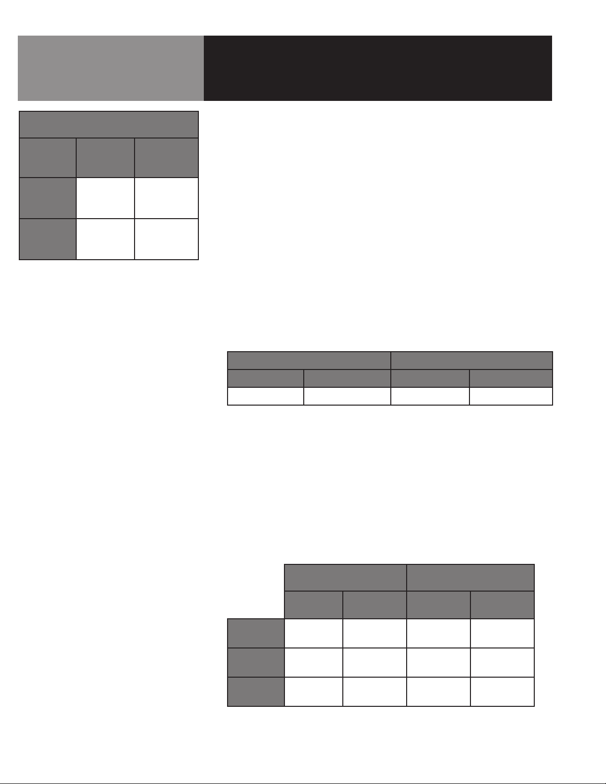
MODEL WIDTH
mm (in)
DEPTH
mm (in)
HEIGHT
mm (in)
WEIGHT
Kg (lbs)
HY-6G(CE) 549 (21.6) 894 (35.2) 1464 (57.6) 193 (425)

8 OM-HY/6G(CE)
Installation
Installation pipe work must be fitted in accordance with IGE/UP/2.
The appliance governor is suitable for both natural and propane gas without
conversion. The governor is incorporated in the gas control valve, which is inside
the control cabinet.
Connection to the gas supply can be completed with ½” B.S.P.T. pipe. Although
the immediate connection to the appliance is ½” B.S.P.T., gas supply piping must
be large enough to provide 90,000 BTU/hour. Minimum supply pressure must be
20 mBar for natural gas, or 37 mBar for propane gas.
An isolating cock must be located close to the appliance to allow shut down in
an emergency, or for servicing. The installation must be tested for gas soundness
and purged as specified in IGE/UP/1.
3. Gas Pressure Adjustment
Gas pressure has been set at the factory but should be checked by connecting
a manometer to the pressure tap on the burner manifold. The adjusted gas
pressures is shown in the table below.
If necessary, the gas pressure may be readjusted as described in the Service
Manual.
NOTE: With reference to gas rate, pressure adjustments and conversions, this
appliance is CE-approved for use with C20 natural gas and G31 propane gas in
Ireland and the United Kingdom.
Use of the appliance with non-approved gases in a listed country, or use in other
countries, will void CE certification.
4. Injector Diameters
GAS INPUT RATE BTU/HR & KW
HY-6G(CE)
Natural Gas
9.25 mBar
(3.7 in. W.C.)
Propane Gas
26.25 mBar
(10.5 in. W.C.)
Individual
Steamer
Cavity
40,905
BTU/hr
12 KW
40,905
BTU/hr
12 KW
Total:
Both
Cavities
81,900
BTU/hr
24 KW
81,900
BTU/hr
24 KW
G20 NATURAL GAS G31 PROPANE GAS
mBar Inch W.C. mBar Inch W.C.
9.25 3.7 26.25 10.5
NATURAL GAS PROPANE GAS
Injector Dia.
(mm)
No. of
Injectors
Injector Dia.
(mm)
No. of
Injectors
Main
Burner 1.49 4 x 2 0.94 4 x 2
Standby
Burner 0.99 1 x 2 0.57 1 x 2
Pilot
Burner 0.60 1 0.25 1

OM-HY/6G(CE) 9
5. Burner Air Adjustment
The unit is equipped with fixed aeration type burners which have no provision for
air inlet adjustment.
6. Equipotential Terminal
In accordance with national regulations, each unit is fitted with an equipotential
terminal.
7. Water Supply Connection (Treated Water)
The HY-6G CE model is fitted for a 3/4 inch B.S.P.T. cold water connection. The
water supply must be provided at a rate of not less than 2.7 liters (0.70 gallons)
per minute. Pressure must be 2.0 to 4.0 Bar (30 to 60 PSI) maximum.
Water quality minimums require totally dissolved solids (T.D.S.) of 30 parts per
million maximum, and a water pH of 7.0 or greater. If the available water supply
fails to meet these requirements, water treatment equipment must be provided
to ensure steamer reliability and operating life.
Install a WRAS approved double-check valve or an equally effective back-flow
preventive device in the incoming cold water line at the point of connection(s)
to the steamer and in compliance with all local plumbing codes. This installation
must be per WRAS-IRN R160 Schedule 2-15(1). For units with the dual water
connection option, a double-check valve shall be installed on each water line.
Do not allow the connection to have any leak, regardless of how small.
8. Untreated Water Second Connection
As discussed previously, the flow of water used for steam suppression in
the drain is much greater than the amount of water used to generate steam.
The second connection on steamers (see illustration under “Water Quality &
Treatment” section) permits the installer to supply treated water to the steam
generator and untreated water to the drain. With “split water” feature, the initial
fill requirement for treated water is 3.5 U.S. gallons (19 L) within 2.5 minutes.
The requirement for treated makeup water is 0.12 gallon (0.45 L) per minute per
cavity. A field retrofit kit is available for single water connection if required.
9. Drain Connection
The HY-6G (CE)Steamer must be leveled front to back. A 38mm (1½ inch) ID
hose may be attached to the drain pipe (supplied) by means of a hose. DO NOT
CONNECT THE HOSE DIRECTLY TO A BUILDING DRAIN. There must be a free air
gap between the end of the hose and the building drain. The free air gap should
be as close as possible to the unit drain. There must also be no other elbows or
other restrictions between the unit drain and the free air gap.
Install the drain line with a constant downward pitch.
IMPORTANT: Do not allow any water traps in the line. A trap can cause pressure to
build up inside the cavity during steaming, which will make the door gasket leak.
CAUTION
DO NOT USE PLASTIC PIPE. THE DRAIN MUST
WITHSTAND HOT WATER.
Installation
Gas input is through a ½ inch B.S.P.T
connection at the left rear of the unit.

10 OM-HY/6G(CE)
Initial Start-Up
After the HY-6G(CE) Steamer has been installed, test it to ensure that the unit is
operating correctly.
1.
Remove all literature and packing materials from the interior and exterior of the unit.
2. Make sure the water supply line is open.
3. Make sure that the gas supply line is open and that the manual knob on the main
gas valve is turned to the “on” position. This valve is located behind the front access
panel on the right side of the unit.
4. Turn on electrical service to the unit. The HY-6G(CE) will not operate without
electrical power. Do not attempt to operate the unit during a power failure.
5. The steamer will not operate until the pilot burner has been ignited. To light the pilot
burner, activate the pilot switch located at the lower front, next to the main gas valve.
When the pilot ignition sequence has been successful, a green light on the pilot
switch will glow.
6. The “trial for ignition” period is roughly 90 seconds. If the pilot burner does not
light within about 90 seconds after the switch is activated, the ignition system
automatically stops gas flow to the pilot burner and stops the ignition trial. If this
happens, turn off the pilot switch and repeat the trial for ignition. During the initial
start-up, the pilot may require several trials for ignition until all the air is bled from
the gas piping. Subsequent start-ups should require only about 5 seconds to achieve
pilot ignition. Reinstall panel(s). NOTE: See Automatic Operation of Pilot at the end of
this section.
7. Once the pilot burner flame has been established (the green light on the electrical
panel is on), press the ON/OFF touch pad for the desired steamer cavity. The steam
generator will fill with water.
NOTE: The door MUST be closed for the main (high) burner to work.
8. When the steam generator has filled with water, the main and low burners will ignite
automatically. Within 6-8 minutes the READY light will come on, indicating that the
water has reached its standby temperature. When the READY light is displayed, you
may take any one of the following steps:
a. Set the timer to the desired time for timed steaming.
b. Turn the timer knob to the manual ON position for continuous steam.
c. Let the unit stay at standby temperature.
9.
To shut down the unit, press the ON/OFF touch pad into the off position. The steam
generator will then drain. You may also switch off the pilot switch to conserve energy.
10. If the HY-6G(CE) Steamer behaves as described, the unit is functioning correctly and
ready for use.
WARNING
WHEN YOU OPEN THE DOOR, STAY AWAY
FROM STEAM COMING OUT OF THE UNIT.
THE STEAM CAN CAUSE BURNS.

OM-HY/6G(CE) 11
Initial Start-Up
11. Automatic Operation of Pilot
Once the pilot burner is lit, it essentially functions as a standing pilot. In this state,
if the pilot is accidentally extinguished (by a very strong gust of wind for example),
it will re-ignite automatically. The unit will completely shut down for a few seconds
while the pilot is re-ignited.
Then the unit will come back on and resume operation in the mode and with the
(running) timer value existing just prior to shutdown. The pilot switch may be
turned off during “off hours” to conserve energy.
After the unit has been running, if the pilot burner ever fails to re-ignite
automatically within 90 seconds, wait 5 minutes before you attempt to reactivate
it. In the unlikely event that ignition problems persist, contact your authorized
Groen Service Agency.
NOTE: For operation at high altitudes (2000 feet and above) please consult the
Groen Food Service Engineering Department.
12. Gas Type Conversion (See Paragraph 3 on page 9 for important information for gas
conversion. Verify the type of gas to be used).
To change the type of gas used (e.g. G20 to/from G31) change the following:
Burner injector, Pressure setting on Main Gas Valve, Data plate, Gas pressure
Regulator Springs
The governor spring does not need to be changed; only the pressure setting.
ALL CONVERSIONS MUST BE FOR APPROVED GAS IN THE COUNTRIES LISTED IN
PARAGRAPH 3 ON PAGE 9.

12 OM-HY/6G(CE)
Operation
A. Controls
Operator controls are on the front right of the unit. The control panel has the
following touch pads and indicator lights. (Your controls may have either words
or the symbols shown below):
• The ON/OFF touch pad gets the HyPerSteam ready for use, or shuts it off.
• The READY indicator light shows that the steam generator is at standby
temperature and the cavity is hot enough to begin steaming.
• The CLEAN indicator lights when the unit is operating in the cleaning mode.
• The SERVICE indicator light shows when the water level probes have stopped
working, and need to be cleaned (normally an indication of lime deposits).
When one probe is not working, the SERVICE light flashes briefly every few
seconds. When both probes fail, the light will flash continuously and the
beeper will sound.
• The HI TEMP indicator light comes on when the steam generator is too hot.
The unit will automatically shut off, and cannot be turned on again until it has
been serviced.
• The CLEAN touch pad is used to start the automatic 50 minute cleaning cycle.
The timer is used in three ways:
1. In the OFF position the steam generator stays at a low boil or “holding”
temperature.
2 When a cook time is set, the unit steams until the timer reaches OFF. The
steaming stops, a red light comes on and a beeper sounds.
3 With the timer turned to the ON position, the unit steams continuously. The
green light stays lit. The steamer will not time down.
Gas Lockout Indicator and Reset Control:
Should the pilot fail to ignite during start-up, a yellow indicator on the control
panel (see page 11) will light and the supply of gas to the unit will be halted.
When this occurs, the ignition process may not be started again for five minutes.
After that time, press the Lockout Reset Switch located behind the front panel
and attempt to start the unit again. If the lockout continues to occur after three
attempts, contact your Groen Service Agency for assistance.
B. Operating Procedure
1. Press the ON/OFF touch pad for the steamer. The steam generator will fill,
and heat until the READY light comes on. (About 10 minutes.)
WARNING
WHEN YOU OPEN THE DOOR, STAY AWAY
FROM THE STEAM COMING OUT OF THE
UNIT. THE STEAM CAN CAUSE BURNS.
WARNING
ANY POTENTIAL USER OF THE EQUIPMENT
SHOULD BE TRAINED IN SAFE AND CORRECT
OPERATING PROCEDURES.
Power
ON/OFF
Button
Power
Indicator
Light
Service
Indicator
Light
Clean
Button
Steamer
Timer
Ready
Indicator
Light
Delime
Indicator
Light
Hi Temp
Indicator
Light Gas
Lockout
Indicator
Light

OM-HY/6G(CE) 13
Operation
2. Load food into pans in uniform layers. Pans should be filled to about the
same levels, and be even on top. The maximum allowable weight of food is
9.8 kilograms (21.6 lbs.) per pan.
3. Open the door and slide the pans onto the supports. If you will only be
steaming one pan, put it in the middle position.
4. Close the door. With the READY indicator lit, take one of the following steps:
• If you want to steam the food for a certain length of time, set the
timer for that period. The timer will automatically run the steamer for
the set time and then turn it off. A red light will come on and a beeper
will sound. Steam production stops.
• To steam continuously, turn the timer to the manual ON position. A
green light will come on. The unit will continue steaming until you
stop it by turning the timer to OFF. When steaming continuously YOU
MUST CONTROL STEAMING TIME.
5. Open the door. Remove the pans from the steamer, using hot pads or oven
mitts to protect your hands from the hot pans.
6. To shut down the unit, press the ON/OFF touch pad OFF. The steam
generator will drain.
WARNING
WHEN YOU OPEN THE DOOR, STAY AWAY
FROM THE STEAM COMING OUT OF THE
UNIT. THE STEAM CAN CAUSE BURNS.
Power
ON/OFF
Button
Power
Indicator
Light
Service
Indicator
Light
Clean
Button
Steamer
Timer
Ready
Indicator
Light
Delime
Indicator
Light
Hi Temp
Indicator
Light Gas
Lockout
Indicator
Light

14 OM-HY/6G(CE)
Cleaning
WARNING
DISCONNECT THE POWERSUPPLY BEFORE
CLEANING THE OUTSIDE OF THE STEAMER.
KEEP WATER AND CLEANING SOLUTIONS
OUT OF CONTROLS AND ELECTRICAL
COMPONENTS.NEVER HOSE OR STEAM
CLEAN ANY PART OF THE UNIT.
DON’TMIX DE-LIMING AGENTS (ACID) WITH DE-
GREASERS (ALKALI) ANYWHERE IN THE UNIT.
AVOID CONTACT WITH ANY CLEANERS,
DE-LIMING AGENT OR DEGREASER AS
RECOMMENDED BY THE SUPPLIER. MANY
ARE HARMFUL. READ THE WARNINGS AND
FOLLOW THE DIRECTIONS!
EVEN WHEN THE UNIT HAS BEEN SHUT OFF,
DON’T PUT HANDS OR TOOLS INTO THE
COOKING CHAMBER UNTIL THE FAN HAS
STOPPED TURNING.
DON’T OPERATE THE UNIT UNLESS THE
TWO REMOVABLE INTERIOR PARTITIONS
HAVE BEEN PUT BACK IN THEIR PROPER
LOCATIONS.
DON’T USE ANY CLEANINGORDELIMING
AGENT THAT CONTAINS ANY SULFAMIC
AGENT OR ANY CHLORIDE, INCLUDING
HYDROCHLORIC ACID (HCl).TOCHECK FOR
CHLORIDE CONTENTSEE ANY MATERIAL
SAFETY DATA SHEETS PROVIDED BY THE
CLEANING AGENTMANUFACTURER.
To keep your HY-6E Steamer in proper working condition/order, use the following
procedure to clean the unit. This regular cleaning will reduce the effort required to
clean the steam generators and cavities.
A. Suggested Tools
a. Mild detergent
b. Stainless steel exterior cleaner such as Zepper®
c. Steam generator de-liming agent, such as Groen Delimer Descaler,
or an equivalent. A liquid de-liming agent will be easier to use than
crystals or powders. See the warning about chlorides, below
d. De-greaser, such as EncompasS®, Malone 34®, Puritan Puribrute®, or
Con-Lie®
e. Cloth or sponge
f. Plastic wool or a brush with soft bristles
g. Spray bottle
h. Measuring cup
i. Nylon pad
j. Towels
k. Plastic disposable gloves
l. Funnel
B. Procedure
1. Outside
a. Prepare a warm solution of the mild detergent as instructed by the
supplier. Wet a cloth with this solution and wring it out. Use the moist
cloth to clean the outside of the unit. Do not allow freely running liquid
to touch the controls, the control panel, any electrical part, or any
open louver.
b. To remove material which may be stuck to the unit, use plastic wool,
a fiber brush, or a plastic or rubber scraper with a detergent solution.
c. Stainless steel surfaces may be polished with a recognized stainless
steel cleaner such as Zepper®.
2. Steam Generator and Cooking Chamber
The steamer cavity and steam generator may be cleaned separately. When
cleaning is scheduled, or if the SERVICE light is on, follow these simple
deliming instructions. REMEMBER: DON’T ALLOW DE-LIMING AGENTS TO
MIX WITH DEGREASERS.
a. Set the timer to OFF position.
b. Turn off the steamer for five minutes.
c. Open the door and allow the cavity to cool.
d. After the cavity has cooled five minutes, make sure that the fan has
stopped and remove the fan baffle partition by lifting it up and toward
the center of the cavity.
IMPORTANT
DO NOT USE ANY METAL MATERIAL (SUCH
AS METAL SPONGES) OR METAL IMPLEMENT
(SUCH AS A SPOON, SCRAPER OR WIRE
BRUSH) THAT MIGHT SCRATCH THE SURFACE.
SCRATCHESMAKE THE SURFACE HARD TO
CLEAN AND PROVIDE PLACES FOR BACTERIA
TO GROW. DONOT USE STEEL WOOL, WHICH
MAY LEAVE PARTICLES IMBEDDED IN THE
SURFACE WHICH COULD EVENTUALLY CAUSE
CORROSION AND PITTING.

OM-HY/6G(CE) 15
Cleaning
e. Wipe out the cavity. Make sure the drain holes at the back of the cav-
ity are clear of debris.
f. Hold down the CLEAN button while turning the steamer on. Continue
holding it until the CLEANING indicator light comes on. Then release
the button. After five minutes, the beeper will begin to beep rapidly.
This is the signal to add 500 ml per cavity of Groen De-limer De-
Scaler (P/N 114800), Lime-Away® or equivalent as shown at right.
Do not use any delimer that contains chlorine.
g. Replace fan baffle partition and close door.
h. The cleaning cycle consists of a boiling clean stage, a soak stage, and
a rinse stage. The full cycle takes about 50 minutes to complete.
i. WEAR PROTECTIVE GLOVES AND EYE PROTECTION FOR THIS STEP.
When the steamer beeper sounds, turn off the steamer and open the
door. After the fan has stopped, remove the fan baffle partition and
rinse it well in a sink. Wipe out the cavity completely. If necessary, use
a damp nylon pad.
j. Reinstall the fan baffle.
k. If the steamer will no longer be used, leave it off. Otherwise, wait
10 minutes and turn it back on. When the READY light comes on, the
steamer is ready for operation.
B. If the SERVICE light stays on:
1. Check that the water supply is on and that the supply hose is not
kinked. With the problem corrected, turn the steamer off or 10 sec-
onds and then re-start.
2. Repeat steam generator cleaning.
Once the cavity has cooled down,
reach-in and remove the fan baffle par-
tition by lifting it upward and drawing it
toward the center of the cavity.
Pour 500 ml of Groen de-liming solution
or Lime-Away® into the de-liming port.
The process for de-liming your HY-6G (CE)
Steamer is simple, tool-less and quick.

16 OM-HY/6G(CE)
Maintenance
The HY-6G(CE) Steamer is designed for minimum maintenance, and no user adjustments
should be necessary. Certain parts may need replacement after prolonged use. If there
is a need for service, only Groen personnel or authorized Groen representatives should
perform the work.
Always supply water with a low mineral count that meets the standards outlined in the
Water Quality & Treatment section of this manual.
If steam or condensate is seen leaking from around the door, take the following steps:
1. Check the door gasket. Replace if it is cracked or split.
2. Inspect the cooking chamber drain to be sure it is not blocked.
3. Adjust the latch pin to allow for changes that might occur as the gasket ages.
a. Loosen the lock nut at the base of the latch pin. Turn the latch pin ¼ turn
clockwise, and re-tighten the lock nut.
b. After adjustment, run the unit to test for further steam leakage.
c. If there is still leakage, repeat the adjustment.
d. Continue adjusting the pin clockwise until the door fits tightly enough to
prevent leakage.
NOTE
THE UNIT CONTAINS NO FUSES THAT SHOULD
BE REPLACED BY THE OPERATOR.

OM-HY/6G(CE) 17
Troubleshooting
This Groen Steamer is designed to operate smoothly and efficiently if properly maintained. However, the following is a list of
checks to make in the event of a problem. Wiring diagrams are furnished inside the service panel. If an item on the check list
is marked with (X), it means that the work should be done by a factory-authorized service representative.
SYMPTOM WHO WHAT TO CHECK
Pilot will not light. User a. Are electrical connections made with a ground?
b. Is gas supply connection made?
c. Is pilot ignition switch on?
d. Is gas valve turned on?
e. Are building fuses or circuit breakers all right?
f. Are there drafts which could blow out the pilot?
Authorized
Service Rep Only
g. Is spark ignition cable connected to module? X
Steam generator does not ll
with water.
User a. Is the ON/OFF touch pad depressed?
b. Is the water supply connected?
c. Is the water turned on?
d. Check for low water pressure (less than 210 kPa or 30 PSI).
e. Is the screen at the water connection clogged?
f. Has the steam generator been delimed?
No steam. User a. Is the ON/OFF touch pad depressed?
b. Is the water supply connected?
c. Is the water turned on?
d. Are steamer doors open?
e. Is the steam generator limed up?
Red light comes on after four
minutes.
User a. Is the water supply connected?
b. Is the water turned on?
c. Has the unit been delimed? (Refer to Cleaning Section)
Excessive steam escaping
from rear of unit.
User a. Is the water spray hose kinked or obstructed?
Authorized
Service Rep Only
b. Is the water spray solenoid connected? X
c. Is the drain properly vented? X

18 OM-HY/6G(CE)
Parts List
External Cabinet & Sheet Metal
Key Description Part #
1 Lower Side Panels 141291
2 Lower Front Panel 141289
3 Adjustable Table Leg 042505
4 Door Assembly 130858
5 Door Handle 129723
6 Door Gasket 124849
7 Left Pan Rack 094148
8 Blower Cover/Rack 096788
9 Door Locking Pin 078914
9a Door Pin Lock Nut 003823
10 Timer Knob 123100
11 Mylar Overlay Plate 123128
12 Vent Pipe 141346
13 Upper Right Side Panel 139941
14 Lower Back Panel 139945
15 Sink Drain Fitting 099943
16 Upper Left Panel 139942
17 Top Panel 143116
18 Flue Cover 096765
19 Flue 096854
20 Back Panel -
21 Timer 100983
22 Equipotential Terminal Assy. 122021
23 Water Supply Adapter Assy. 122144
24 Gas Lockout Indicator Light 122122
25 BSPT to NPT Adapter 116392

OM-HY/6G(CE) 19
Parts List
Cavity Control Section
Key Description Part #
1 Top Cover Clip 123156
2 Timer 100983
x Door Switch 096857
4 Ready Thermostat 088865
5 Steam Port 088874
6 Steam Port Gasket 099250
7 Steam Hose, Top 099953
8 Steam Hose, Bottom 088880
9 1-3/8” Hose Clamp 127525
10 Fan Motor 096740
11 Motor Capacitor, 3 MFD 096813
12 Cover, Control Panel 128800
13 Steamer Control PC Board 137221
14 Transformer 119815
15 Timer Board 119817
16 Top Cavity Drain Hose 088847
x Bottom Cavity Drain Hose 088846
x = not shown

20 OM-HY/6G(CE)
Parts List
Steamer Base Section
Key Description Part #
1 Terminal Block 003887
2 Cover, Housing 128766
3 Relay, 12V DC 119813
4 Water Level Probes 070178
5 Relay, 24V DC 119814
6 Reset Relay 24VAC 074842
7 Transformer 100 VA, 240V 146011
8 Controller, Pilot Ignition 154059
9 Gas Pilot Switch, Rocker 087951
10 Reset Switch, Pushbutton 122003
11 Circuit Breaker, 10 Amp 119860
12 Lug, Ground 119829
13 Main Gas Valve 122158
14 Regulator 100513
15 Steam Generator Assy. LH 094128
16 Steam Generator Assy. RH 123655
Key Description Part #
1 Gas Valve, 24V 122120
2 1/2” Tubing 123707
3 3/8” Tubing 096712
4 Heat Shield 123711
5 1/2” Tubing 123475
6 3/8” Tubing 123706
7 1/4” Tubing, Pilot 122140
8 Manifold Fitting Assembly 123705
9 Manifold Fitting Assembly 123704
10 Regulator 100513
11 Adjustable Foot 042505
12 Over Temperature Sensor 096892
This manual suits for next models
1
Table of contents