Test Procedure:
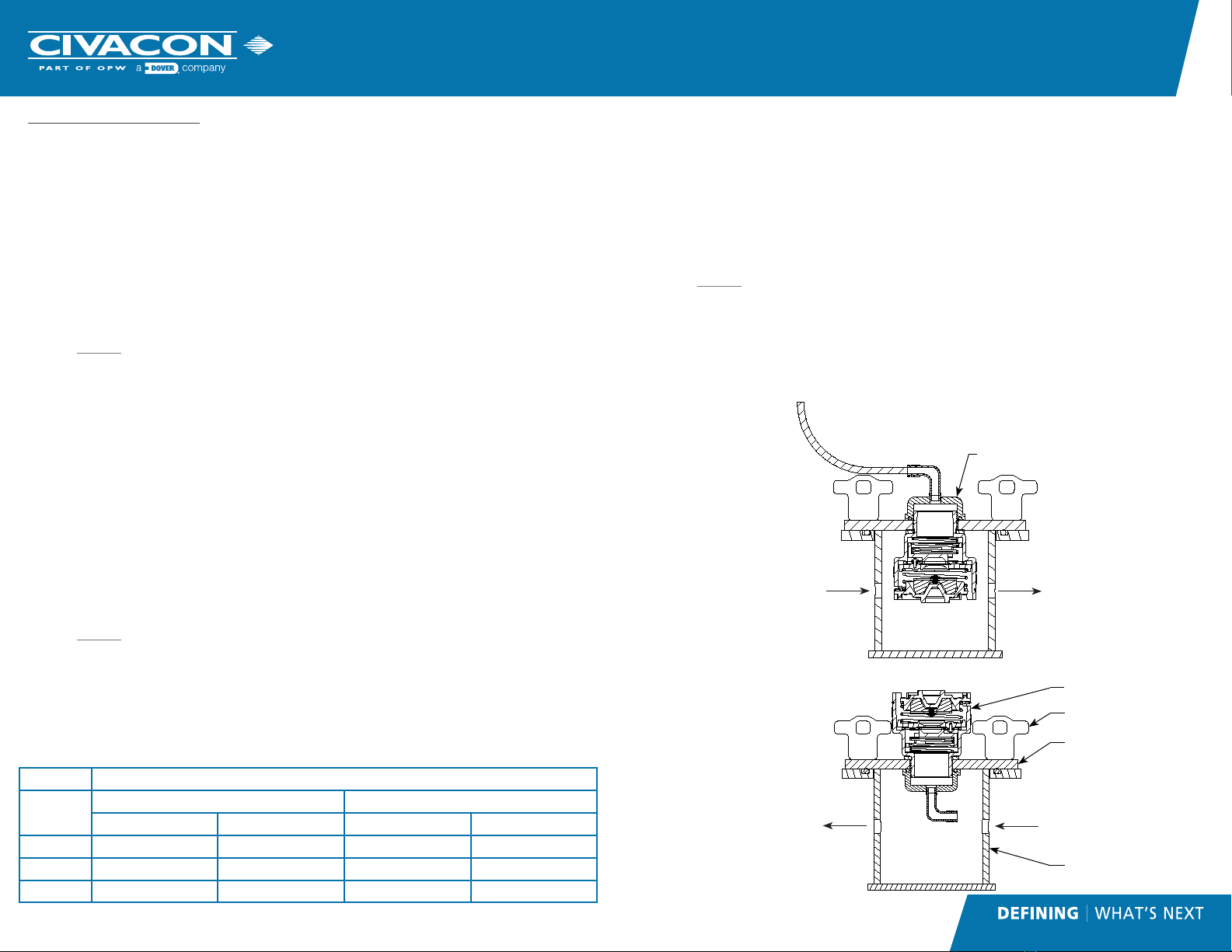
Pressure Test (See Illustration “A”)
1. Intall vent (Item# 5) in the hole in the cover plate (Item# 3) of the vent
test tank (Item# 2). Screw vacuum test cap (Item# 1) on to the threaded
portion of the vent (Item# 5).
2. Install cover plate (Item# 3) and vent (Item#5) onto test tank (Item# 2),
with vent (Item# 5) pointing downward as shown in the illustration. Use
wing nuts (Item# 4) to fasten the cover plate (Item# 3) to the test tank
(Item#2).
3. Attach a short length of hose to the vacuum test cap (Item#1) and run it
to a small container of water. Keep the end of the hose 1/4” below the
surface of the water.
4. Slowly apply pressure, and take note at what pressure the bubbles start
coming out of the hose. Note the pressure reading on the gauge or the
manometer.
5. The measured pressure level should fall in the range found in Table 1 for
the specific vent model being tested. If the vent does not pass the test, it
must be cleaned, repaired or replaced.
Vacuum Test (See Illustration “B”)
1. Intall vent (Item# 5) in the hole in the cover plate (Item# 3) of the vent
test tank (Item# 2). Screw vacuum test cap (Item# 1) on to the threaded
portion of the vent (Item# 5).
2. Install cover plate (Item# 3) and vent (Item#5) onto test tank (Item# 2),
with cap inside the tank as shown in the illustration. Use wing nuts
(Item# 4) to fasten the cover plate (Item# 3) to the test tank (Item#2).
3. Spray water/soap solution areound the two black poppets on the side of
the vent.
4. Slowly apply pressure, with the vent in the orientation shown in the
illustration. Take note at what pressure the bubbles start being produced
from the sealing surface. Note the pressure reading on the gauge or the
manometer.
5. The measured vacuum level should fall in the range found in Table 1 for
the specific vent model being tested. If the vent does not pass the test, it
must be cleaned, repaired or replaced.
Overturn Test (See Illustration “A”)
1. Intall vent (Item# 5) in the hole in the cover plate (Item# 3) of the vent
test tank (Item# 2). Screw vacuum test cap (Item# 1) on to the threaded
portion of the vent (Item# 5).
2. Install cover plate (Item# 3) and vent (Item#5) onto test tank (Item# 2),
with vent (Item# 5) pointing downward as shown in the illustration. Use
wing nuts (Item# 4) to fasten the cover plate (Item# 3) to the test tank
(Item#2).
3. Set pressure regulator between 4 and 5 psi (27.6 kPa and 34.5 kPa).
Slowly apply pressure until the air is exhausting out the top or the vent.
4. Rotate test fixture 90 degrees and attach a short length of hose to the
vacuum test cap (Item# 3) and run it to a small container of water. Keep
the end of the hose 1/4” below the surface of the water. A steady
stream of bubbles would represent a failure. This overturn test must be
repeated at an angle of 180 degrees and 270 degrees. If the vent fails at
any of the three orientations, it must be cleaned, repaired or replaced.
TABLE 1 REQUIRED SETTINGS
PART
NUMBER
PRESSURE VACUUM
MIN. MAX. MIN. MAX,
NV4000 1.0 PSI (27.7”H20) 1.5 PSI (41.5” H20) .25 PSI (7.0” H20) .375 PSI (10.4” H20)
NV4000C .87 PSI (6 kPa) 1.16 PSI (8 kPa) .29 PSI (2 kPa) .43 PSI (3 kPa)
NV4000E 1.0 PSI (69 mbar) 1.74 PSI (120 mbar) .25 PSI (17 mbar) .29 PSI (25 mbar)
Air out to small container
of water to see bubbles
when valve opens
Air in from regulator
(0-5 PSI)
Air out to manometer or
low pressure gauge
ILLUSTRATION “A”
POSITIVE PRESSURE TEST POSITION
ILLUSTRATION “B”
VACUUM TEST POSITION
Air out to manometer or
low pressure gauge
Air in from regulator
(0-5 PSI)
1
4
3
5
2