Dover Marathon RAMJET Signature Series User manual

OPERATION, MAINTENANCE,
AND INSTALLATION
MANUAL
FOR
RJ-88SC RJ-100SC
RJ-250SC RJ-250SC Ultra
Includ s HT (Hydraulic Tailgat ) Units and
SL (Str amlin , Liquid R moval) Units
SELF-CONTAINED
COMPACTOR CONTAINER
Marathon Equipm nt Co. OMI Manual No. 0018 R v. 1/11

2
Tabl of Cont nts
Introduction .............................................................................................................. 3
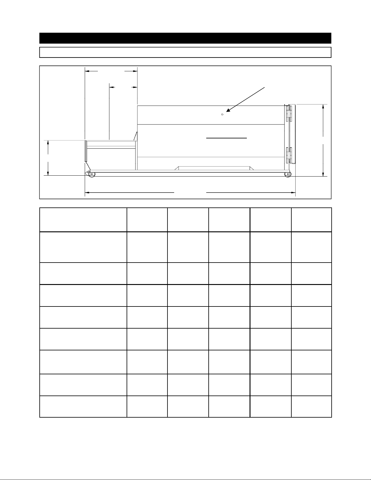
Specifications ............................................................................................................ 4
Pre-Operating Instructions .......................................................................................... 5
Control Panel ............................................................................................................. 6
Operating Instructions - Standard Models .................................................................... 7
Operating Instructions - Models ith Photoelectric Cycle Control .................................... 8
Optional Controls ....................................................................................................... 9
Decals ...................................................................................................................... 10
Decal Placement ........................................................................................................ 11
Decal Images ............................................................................................................ 12
Decal Placement for Optional Loading Configuration ..................................................... 13
Additional Decals for Hydraulic Tailgate (HT) Units ....................................................... 14
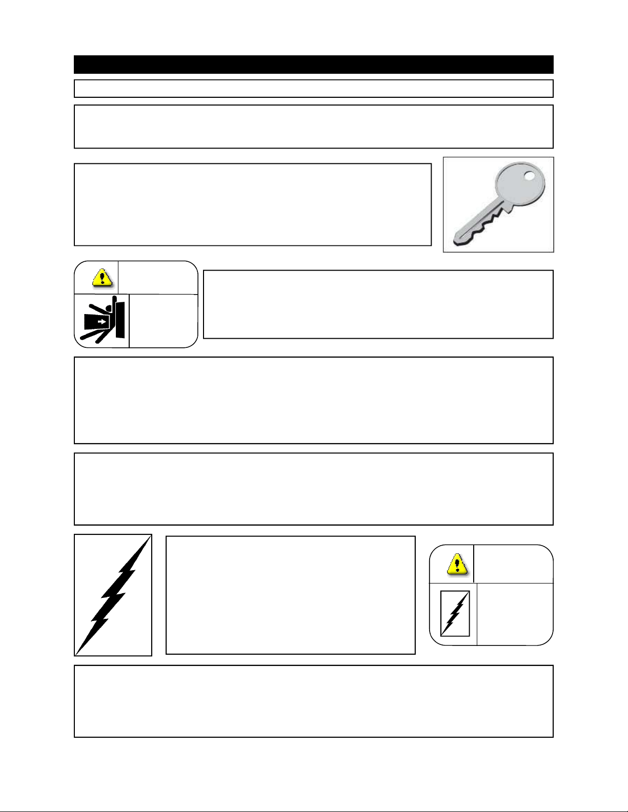
Lock-Out & Tag-Out Instructions .......................................................................... 16
Periodic Maintenance ................................................................................................. 17
Procedures - (Hydraulic System Pressure Check) .......................................................... 18
Principles of Operation ............................................................................................... 19
Cylinder Removal ....................................................................................................... 19
Tailgate Seal Replacement .......................................................................................... 20
Fuse & Circuit Breaker ................................................................................................ 21
Wire Sizes/Heater Element ......................................................................................... 22
Typical Panel Box....................................................................................................... 23
PLC - Layout and Description ...................................................................................... 24
PLC - Maintenance and Programming .......................................................................... 25
Po er Unit - Standard 5 HP ....................................................................................... 26
Po er Unit - Standard 5 HP - (Parts List) .................................................................... 27
Po er Unit - Standard 10 HP - (MECO) ........................................................................ 28
Po er Unit - Standard 10 HP - (Parts List) (MECO) ....................................................... 29
Po er Unit - Standard 10 HP - (NON MECO) ................................................................ 30
Po er Unit - Standard 10 HP - (Parts List) (NON MECO) ............................................... 31
Po er Unit - Submerged 10 HP ................................................................................... 32
Po er Unit - Submerged 10 HP - (Parts List) ................................................................ 33
Hydraulic Schematic - Typical ..................................................................................... 34
Troubleshooting ....................................................................................................... 35
Concrete Pad Requirements ........................................................................................ 37
Steel Installation Procedures ....................................................................................... 38
Electrical & Hydraulic Installation ................................................................................ 39
Through-The-Wall Po er Unit Installation .................................................................... 40
Hauler Instructions - General ...................................................................................... 42
Hauler Instructions - Door/Latch Operation .................................................................. 43
Hauler Instructions - Hydraulic Tailgate Operation (for optional HT units) ....................... 44
Hauler Instructions - Tailgate Maintenance Bar (for optional HT units) ........................... 45
Hauler Instructions - Liquid Removal (for optional SL units) ........................................... 46
OPERATION
INSTALLATION
MAINTENANCE
HAULER INFORMATION
© 2011 Marathon Equipm nt Company

3
1 OPERATION
INTRODUCTION
THANK YOU FOR PURCHASING A MARATHON
SELF-CONTAINED COMPACTOR/CONTAINER.
This compactor is designed to give you reliable and superior performance for many
years to come. The purpose of this manual is to provide the o ner and operator ith
the necessary information to properly and safely install, operate, and maintain your
self contained compactor. Also included are sections regarding troubleshooting and
service procedures. The manual is not intended as a primary training source, but as a
reference guide for authorized, trained personnel. Each person involved in the
operation, maintenance and installation of the machine must read and thoroughly
understand the instructions in this manual and follo ALL WARNINGS.
The employer involved in the operation, maintenance, and installation of the
compactor must also read and understand the most current version of the follo ing
applicable standards:
ANSI Standard No. Z245.2, “Stationary Compactors Saf ty R quir m nts”
A copy of this standard may be obtained from:
ANSI
25 West 43rd Street
Ne York, NY 10036
OSHA 29 CFR, Part 1910.147
“The control of hazardous energy (lockout/tagout)”
Any service or repair instructions contained in this manual should be performed by factory
authorized personnel only. If you should need assistance ith your baler, please contact your
distributor.
When contacting your distributor, you ill need to provide:
Compactor Serial Number:___________________________
Installation Date:______________________________
Electrical Schematic Number:____________________
IF YOU HAVE ANY SAFETY CONCERNS WITH EQUIPMENT, OR
NEED FURTHER INFORMATION, PLEASE CONTACT US AT:
Marathon Equipm nt Company
Attn: RamJ t
®
S rvic D partm nt
P.O. Box 1798
V rnon, Al 35592-1798
1-800-633-8974

4
1 OPERATION
SPECIFICATIONS
“B”
“D”
“C”
“E”
Contain r
Compactor
SIDE VIEW
Fire Hose Port
One per Side
88SC 100SC 250SC 250SC
ULTRA 250SC HT
"A", Clear Top Opening
(Length x Width) (inches) 30 1/2 x 48 35 x 60 41 1/2 x 60 41 1/2 x 60 41 1/2 x 60
"B", (inches) 70 76 1/8 67 67 67
"C", (inches) 43 48 48 48 48
"D", (max.) (inches) 95* 104* 104* 104* 102*
"E", (max.) (inches) 284 1/2* 290 299 1/2* 269* 277*
Charg Box Capacity
(cubic yards) 1.0 1.50 1.70 1.70 1.70
WASTEC Rating .70 1.32 1.31 1.31 1.31
Cycl Tim (seconds) 44 37 33 33 33
* Determined by the size and capacity of the container.
“A”

5
1 OPERATION
PRE-OPERATION INSTRUCTIONS
NEVER ENTER ANY PART OF THE COMPACTOR UNLESS THE
DISCONNECT SWITCH HAS BEEN LOCKED-OUT AND TAGGED-OUT.
S Lock-Out & Tag-Out instructions in th Maint nanc s ction.
Before starting the compactor, be sure no one is inside. Be certain that every-
one is clear of all points of operation and pinch point areas before starting.
THE EMPLOYER SHOULD ALLOW ONLY AUTHORIZED
AND TRAINED PERSONNEL TO OPERATE THIS
COMPACTOR. This compactor is equipped ith a key operated
locking system. The key (s) should be in the possession of
authorized personnel.
DO NOT REMOVE ACCESS COVERS EXCEPT FOR SERVICING. Only authorized
service personnel should be allo ed inside. All access doors on the compactor body
should al ays be secured in place hen the unit is operating. S Lock-Out & Tag-
Out instructions in th Maint nanc s ction.
FEDERAL REGULATION PROHIBITS THE USE OF THIS
EQUIPMENT BY ANYONE UNDER 18 YEARS OF AGE.
STAY CLEAR OF ALL INTERNAL PARTS OF THE
S E L F - C O N T A I N E D C O M P A C T O R / C O N T A I N E R
DURING OPERATION. FAILURE TO DO SO COULD
RESULT IN SERIOUS INJURY OR DEATH!
DO NOT
ENTER
DANGER
ONLY AUTHORIZED PERSONNEL
SHOULD BE ALLOWED INSIDE
THE MOTOR CONTROL PANEL.
The motor control panel contains
high voltage components.
S Lock
-Out & Tag-Out Instructions in
th Maint nanc s ction.
DANGER
460
VOLTS
If the compactor is equipped ith a security gate or doghouse ith security door,
BE SURE THAT THE SECURITY GATE OR DOOR IS CLOSED BEFORE THE
COMPACTOR IS STARTED.

6
1 OPERATION
CONTROL PANEL
OPERATOR
STATION
FOR 88SC, 100SC,
250SC, & 250 ULTRA
MANUAL - OFF - AUTOMATIC SWITCH*
KEYED START SWITCH
REVERSE PUSHBUTTON
EMERGENCY STOP PUSHBUTTON
*Optional equipment - not included on standard models
CONTROL DESCRIPTION
1. MANUAL - OFF - AUTOMATIC SWITCH - (
Optional Equipment - not included on
standard models
) This s itch controls the compactor operation mode, manual or automatic
(automatic is photocell mode).
2. KEYED START SWITCH - This s itch requires a key for operation. Insert the key and
turn clock ise to the START position. Depress and hold the key for one to t o seconds
and release. The compactor ill cycle the preset number of times determined by the
Multi-Cycle Counter*, then stop. After use, turn the key to the counterclock ise position
and remove the key.
3. EMERGENCY STOP PUSHBUTTON - When depressed, this pushbutton ill stop all
po ered operation of the compactor.
4. REVERSE PUSHBUTTON - This pushbutton ill reverse the compaction ram hen
depressed. The motor must be running for the REVERSE button to operate. See the
MANUAL OVERRIDE INSTRUCTIONS on the next page for details of the operation.
*For more information on the Multi-Cycle Counter see page 25.

7
1 OPERATION
OPERATING INSTRUCTIONS -
STANDARD MODELS
1. First, place the material to be discarded into the compactor.
Not : If you are loading the compactor through a door or
gate, close it before starting the compactor. Refer to
“Optional Loading Configurations” on page 13 to determine
ho your compactor is configure.
2. Insert the key into the key s itch. Turn it clock ise and
depress for 1 to 2 seconds and release. The unit ill cycle the preset number of times
determined by the Multi-Cycle Counter*, then stop.
3. Repeat, if necessary, after the compactor has stopped.
4. When you have finished using the compactor, remove the key from the key s itch.
*For more information on the Multi-Cycle Counter see page 25
.
DO NOT
ENTER
DANGER
IN CASE OF EMERGENCY:
Push th larg r d button to STOP
MANUAL OVERRIDE INSTRUCTIONS (RAM STOP REAR ONLY)
If th ram is stopp d in any position:
- To move the ram for ard, turn the key s itch clock ise and depress.
- To move the ram rear ard, hold the reverse button do n, turn and
depress the key s itch, release the key s itch, then release the reverse button.
Whil th ram is moving:
- To reverse the ram hile it is moving for ard, press the reverse button.
- To cause the ram to move for ard hile it is moving rear ard, depress the key
s itch.
NOTE: Refer to Optional Controls for Manual Override on Ram Stop For ard
Machines.

8
1 OPERATION
OPERATING INSTRUCTIONS - Mod ls with Photo l ctric Cycl Control
OPERATING INSTRUCTIONS (AUTOMATIC MODE)
1. Place the material to be discarded into the compactor.
NOTE: If you are loading the compactor through a door or
gate, close it before starting the compactor.
2. Insert the first key into the “MANUAL - OFF - AUTOMATIC”
key s itch and turn to the “AUTOMATIC” position.
3. Insert the second key into the “START” s itch and turn to the right.
4. Depress the key in the “START” s itch and hold it continuously for 20 seconds.
•
Both the audible and visual start-up alarms ill energize for 5 seconds.
•
After 5 seconds the audible alarm ill stop, but the
visual alarm ill continue for an additional 15 seconds
(for a total of 20 seconds).
•
After 20 seconds, the motor ill start and the ram ill
extend, then retract (one complete cycle).
•
The light ill continue to flash until the unit is manually
turned off, automatically shuts do n, or is s itched
to manual mode.
•
If 15 minutes elapse ithout a cycle being initiated by
the photocell or ithout operation of any of the
pushbuttons, the po er unit ill shut do n.
DO NOT
ENTER
DANGER

9
1 OPERATION
OPTIONAL CONTROLS
1. SUSTAINED MANUAL PRESSURE CONTROL BUTTON (Hold-To-Run, Release-To-Stop)
This option requires the compactor operator to remain at the push button station hile the
compactor is in use. Actuation requires depressing the "Hold-To-Run" and "Start" buttons.
After the unit has started, the "Start" button is released. If the "Hold-To-Run" button is
released, the unit ill stop instantly.
2. ADVANCE WARNING / CONTAINER FULL LIGHT - When the light starts flashing
(ADVANCE WARNING), then 200 PSI is left before the pressure s itch is activated to shut
the unit off and container is full (unit ill run hen light flashes). When the light stays on
continuously (CONTAINER FULL), the container is full and is ready to be emptied before its
next use. To deactivate the light, depress the illuminated emergency stop button (The unit
ill not run hile the light is continuously on).
3. RAM STOP FORWARD - When a machine ith this option has been stopped, the ram
automatically begins to move rear ard hen restarted. To move the ram for ard
( hen it is stopped), hold the FORWARD button do n, turn the key s itch clock ise,
depress and release the key s itch, then release the FORWARD button. To reverse the
ram hile it is moving for ard, depress the key s itch. To cause the ram to move
for ard hile it is moving rear ard, press the FORWARD button.
4. ACCESS INTERLOCK - This is optional ith units equipped ith doors, chutes, or access
gates. It prevents the unit from operating hile a door or gate is open.
5. PHOTOELECTRIC CYCLE CONTROL - (Photocell) - Consists of a LED light source and a
reflector. It can be mounted on a hopper or chute. T o holes, located so as to prevent any
hazard, are located in opposite alls of the chute. When the light beam is blocked for 15
seconds, the compactor is activated and ill continue to run until the obstruction has been
cleared.
6. AUTOMATIC SHUTDOWN - Used ith the photoelectric cycle control. If a blockage in
the charge chamber causes the compactor to continue cycling, the timer ill shut the
compactor do n after the preset time has passed. To deactivate the timer, the illuminated
pushbutton is pressed after clearing the blockage.
7. THERMOSTATICALLY CONTROLLED OIL HEATER - This option is installed in the oil
reservoir. The thermostat is adjustable so the heater ill heat the oil hen the oil
temperature goes belo a specified level. It is recommended to set the thermostat
bet een 70° F - 100° F.

10
1 OPERATION
DECALS
WARNING DECAL REQUIREMENTS
When your compactor leaves the factory, several WARNING DECALS are installed for your
protection. These labels are subject to ear and abuse due to the nature of operation.
The FOLLOWING DECALS MUST BE MAINTAINED. Additional decals may be purchased
through your distributor or from Marathon Equipment Company by either calling the parts
department at 1-800-633-8974 or going to www.parts1stop.com to place an order
online.
When ordering replacement decals, match the reference numbers in the chart belo ith
the dra ing on th n xt pag (and pages 13 & 14 for optional equipment or HT
models) or look for the part number in the lo er right hand corner of the decal.
Part # R f. # D scription Quantity
05-0325 RIVETS, 1/8 X 1/2 ALUM (to go ith 06-0364) 4
06-0038 1 WARNING DO NOT REMOVE ACCESS COVER 2
06-0039 2 DANGER DO NOT ENTER 3****
06-0067 3 D/N REMOVE CONT TIL REAR... 2
06-0072 4 QUICK CLEAN TANK 1
06-0093 5 FIRE HOSE PORT 2
06-0094 6 NOTICE WIPE OFF SEAL AFTER.... 2
06-0121 7 NOTICE FEDERAL REGULATION...NO <18 y.o. 2
06-0124 8 CYCON 2
06-0249 9 DANGER HAZARDOUS VOLTAGE 2
06-0364 10 COMPACTOR SERIAL NUMBER 2
06-1839 11 AMERICAN FLAG 3
06-0057 12 WARNING STAND CLEAR OF COMPACTOR 3
06-0002 13 RAM-JET 4
06-3123 14 CONFINED SPACE 3****
06-3231 15* ULTRA DECAL 2
06-0040 16** CAUTION: KEEP OUT ****
06-0052 17** CAUTION: GATE MUST BE CLOSED.... ****
06-0104 18*** HT OPERATING INSTRUCTIONS 1
06-0105 19*** DANGER: STAND CLEAR OF TAILGATE... 3
*ONLY ON “ULTRA” MODELS.
**ONLY ON OPTIONAL EQUIPMENT (ACCESS GATES, HOPPERS, &/OR DOGHOUSE.
***ONLY ON HT UNITS (HYDRAULIC TAILGATE).
****QUANTITY VARIES DEPENDING ON OPTIONAL EQUIPMENT, NOTE QUANTITY ON MACHINE.

11
1 OPERATION
DECALS PLACEMENT
* INSTALLED ON BOTH SIDES OF COMPACTOR IN SAME LOCATION
**ALSO INSTALLED ON REMOTE POWER PACK
Match reference numbers to chart on previous page. See next page for decal images.

12
1 OPERATION
DECAL IMAGES
06-0104
06-0124
06-0364
06-0094
06-3231
06-0105 06-0052
06-0093
06-1836 06-0057
06-3123 06-0067
06-0038 06-0249
06-0057
06-0002 06-0121 06-0072

13
1 OPERATION
DECALS - Optional Loading Configurations
Match reference numbers to “Decals” on page 10 when ordering replacement
decals.
ACCESS GATE & HOPPER
2
2 & 17
2
14
16**
14
2*
14*
14
DOCK
* Located on each inside all
** Located on each outside all
DOGHOUSE
THRU-THE WALL
SECURITY CHUTE

14
1 OPERATION
D cals - Additional For Hydraulic Tailgat (HT) Units
In addition to the decals and their placement specified on the previous pages, the self
contained units ith the hydraulic tailgate option require the follo ing decals located as sho n
belo .
HYDRAULIC COUPLING
19, BOTH SIDES 18
19 REAR VIEW
SIDE VIEW

15
This Page Intentionally Left Blank

16
2 MAINTENANCE
LOCK-OUT & TAG-OUT INSTRUCTIONS
FOREWORD: B for nt ring any part of th compactor, b sur that
all sourc s of n rgy hav b n shut off, all pot ntial hazards hav
b n liminat d, and th compactor is lock d-out and tagg d-out in
accordanc with OSHA and ANSI r quir m nts. If the ram is pressing
against a load, move the ram rear ard before shutting the compactor do n.
The specific lock-out and tag-out instructions may vary from company to
company (i.e. multiple locks may be required, or other machinery may need to
be locked-out and tagged-out). The follo ing instructions are provided as
minimum guidelines.
INSTRUCTIONS
1. Mov th main disconn ct l v r to th OFF position.
2. Padlock th disconn ct l v r with a k y d padlock and tak th k y with you.
3. Along with th padlock, plac an appropriat , highly visibl , warning tag on th
disconn ct l v r. Th tag should provid a warning such as:
“Danger: Do not operate equipment. Person orking on equipment.” or
“Warning: Do not energize ithout the permission of ________________.”
4. Aft r locking and tagging th compactor, try to start and op rat th compactor
(as outlin d in th Op rating Instructions) to mak sur th lock-out and tag-
out is ff ctiv . If th lock-out and tag-out is ff ctiv , r mov th k y from
th k y switch and tak it with you.
HYDRAULIC: Stor d hydraulic n rgy must
b r mov d from th compactor hydraulic
circuit for compl t lock-out and tag-out.
Mak sur that this n rgy has b n r li v d
by manually d pr ssing th sol noid valv
pin locat d in th c nt r of ach coil nd of
th dir ctional control valv .
Solenoid Valve
Valve Pin
Po er Unit
ELECTRICAL: Th motor control pan l contains high
voltag compon nts. Only authoriz d s rvic p rsonn l
should b allow d insid th pan l. Authoriz d s rvic
p rsonn l should b allow d insid th pan l only aft r
th compactor has b n lock d-out and tagg d-out.
DANGER
460
VOLTS

17
2 MAINTENANCE
PERIODIC MAINTENANCE
MONTHLY
Check external hoses for chafing, rubbing, or other deterioration and damage.
Check for any obvious unsafe conditions in the compactor area.
Check oil level in hydraulic reservoir. Level should be 3/4 of sight gauge (ram fully retracted).
Clean out or ash out debris from behind compactor ram.
Lubricate the ram guidance tracks using the grease fittings on the compactor side
(For guided ram machines only), and check guide shoes for ear.
THREE MONTHS
1. Check functional operation of controls and options (stop button, timers, lights, etc.).
2. Check hydraulic cylinder, internal hoses, and connections for leakage; check hoses
for chafing and ear.
3. Lubricate the container door hinges.
ANNUALLY
Lubricate electric motor bearings annually per the manufacturers instructions.
FILTER MAINTENANCE
1. The hydraulic filter should be cleaned at regular yearly intervals.
2. The filter may be removed from the unit by disconnecting the union on the suction
side of the pump, removing the four bolts retaining the cover plate, and lifting the
filter from the reservoir.
3. Care should be exercised in cleaning the filter to ensure that the element is not torn.
Clean the element ith a soft brush and standard industrial solvent.
4. Replace the filter after cleaning and tighten the union securely. Pump noise and a
"crackle" sound is most often caused by air entering the pump suction line.
Tightening the suction fittings ill usually eliminate the problem.
RECOMMENDED OILS FOR THE HYDRAULIC SYSTEM
WARNING: RAM SPEED ACCELERATES AS RAM RETRACTS. NEVER ENTER
ANY PART OF THE SELF-CONTAINED COMPACTOR/CONTAINER UNTIL THE
UNIT HAS BEEN LOCKED-OUT AND TAGGED-OUT.
1. Union - Unax-46, Unax-AW46 6. Shell -Turbo 46, Tellus 46
2. Gulf - Harmony 47, Harmony 48-AW 7. Quaker State - Dextron ll (ATF)
3. Exxon - Teresstic 46, Nuto 46 8. Citgo - Pacemaker 46, Tellus - AW46
4. Texaco - Rando 46 9. Amoco - (Rycon)
5. Chevron - AW 46

18
2 MAINTENANCE
PROCEDURES
PRESSURE SETTING INSTRUCTIONS
When the hydraulic cylinders used in the RamJet Self-Contained compactor are fully extended
or retracted, they bypass internally. This makes it impossible for the hydraulic system to reach
relief pressure. Follo the recommendations belo for proper pressure setting.
1. Disconnect and lock-out po er per the procedure on page 16.
2. Using the quick disconnects, disconnect the hydraulic hoses from the compactor.
3. Remove the 1/4” plug from the check valve and install a 0-3000 psi pressure gauge.
4. Loosen the lock nut on the relief valve and turn the adjustment scre several turns
counterclock ise.
5. Remove the lock-out provisions and turn the disconnect to the ON position. Start
the po er unit using the OPERATING INSTRUCTIONS on page 7 and 8.
6. With the hoses disconnected, the po er unit ill build pressure. Adjust the relief
pressure up by turning the relief adjustment scre clock ise. Adjust the relief valve
to the desired pressure setting and tighten the lock nut. See chart belo .
7. Press the EMERGENCY STOP button to stop the po er unit, and relieve the stored
hydraulic energy as described on page 16.
8. Disconnect and lock-out po er as described in Step 1.
9. Remove the pressure gauge and replace the 1/4” plug in the check valve.
10. Reconnect the hydraulic hoses, and remove the lock-out provisions.
PRESSURE SETTINGS
MODEL NO.
HP
GPM
RELIEF
VALVE
SETTING
RES.
CAP.
BORE
ROD
STROKE
RJ-88SC 5 6 1700 15 4 2 1/2 25
RJ-100SC 10 10 1850 20 5 2 1/2 42
RJ-250SC 10 10 1850 20 4 2 1/2 31 5/8
RJ-250 Ultra 10 10 1850 20 4 2 1/2 31 5/8
On units with the Advance Warning ight, set pressure 200 PSI below pressure switch setting.
Includes HT units & S units.

19
2 MAINTENANCE
PRINCIPLES OF OPERATION
STANDARD SYSTEM OPERATING CHARACTERISTICS, 5 hp & 10 hp
The system uses special cylinders to move the ram and t o timers to control the operation of
the ram. When the hydraulic cylinders used in the self-contained compactors are fully
extended or retracted, they bypass internally. This makes it impossible for the hydraulic
system to reach relief pressure. The sequence of operation for this system is as follo s:
Upon startup, a contact is made that energizes the motor starter, starting the electric motor
and at the same time energizing T1 timer coil. When T1 is energized, the valve solenoid shifts
the valve so that the hydraulic oil is directed to extend the cylinder hich extends the ram.
When T1 timer times out, the contacts reverse causing T2 timer to energize and the solenoid
to shift the valve into the reverse position. In this position, the valve directs the hydraulic oil
into the front end of the cylinder causing the cylinder to retract, therefore causing the ram to
retract. When T2 timer times out, the motor starter contact is opened causing the motor
starter to shut do n, therefore causing the motor/po er unit to shut do n.
2 MAINTENANCE
1. Disconnect and lock-out po er per the procedure on page 16.
2. Remove access covers from compactor.
2. Remove hoses (4 for 88SC & 250SC, 2 for 100SC & 250 Ultra).
3. Remove cylinder pins.
4. Remove cylinders (2 for 88SC, 250SC, & 250 Ultra, 1 for 100SC).
5. To install the cylinders, reverse the above steps.
CYLINDER REMOVAL INSTRUCTIONS

20
2 MAINTENANCE
TAILGATE SEAL REPLACEMENT
When the door/tailgate seal becomes damaged or orn, replace the seal.
WARNING: For units with hydraulic tailgat s, b for p rforming any insp ction or
maint nanc on th s al, support th rais d tailgat with a cran , forklift, or oth r
positiv maint nanc prop..
•
When removing the old seals (top & bottom) mark the position of the seal joints.
•
Pry the seal retainer up slightly to allo removal of the old seals.
•
When installing the ne seals, join the seals at the same position.
A A
Ne Seal
Seal retainer -
Pry slightly
up ard so ne
seal can be
inserted
Pry Bar
Ne Seal
Use a plastic or rubber
hammer to tamp the seal
retainer snug against the seal
all the ay around the seal(s)
This manual suits for next models
4
Table of contents
Popular Trash Compactor manuals by other brands

SUMMIT EQUIPMENT
SUMMIT EQUIPMENT SC-3248 Safety, operation & maintenance manual

KitchenAid
KitchenAid KUCS03CTWH0 parts list

GEAppliances
GEAppliances Universal II installation instructions

KitchenAid
KitchenAid 9871780B Use and care guide

Werner & Weber
Werner & Weber MPC-A Operation manual

Glasdon
Glasdon JUBILEE DUO 220 Operating & installation manual