3
connect REMOTEs
Before a remote can connect with
Piggyback the gate motor control
board must be reset.
Press top button on gate motor (right)
until light shows. Then simultaneously
press a remote button.
Release both after light ashes ve
times.
OUTPUT 1: Main Garage door
Press P1 once (once = OUTPUT 1). Light
shows single ashes.
Press and hold a T-button (assigned to
door 1). Release button after third ash of
P1 light.
Add other Mhouse remotes while light
shows single ashes.
OUTPUT 2: 2nd Garage door
These steps are for OUTPUT 2 and only
needed if a second system is added .
Press P1 button twice (twice = OUTPUT
2). Light will double-ash.
Press and hold the T-button (dedicated
to door 2). Release button after third
ash of P1.
Add other Mhouse remotes while light
shows double ashes.
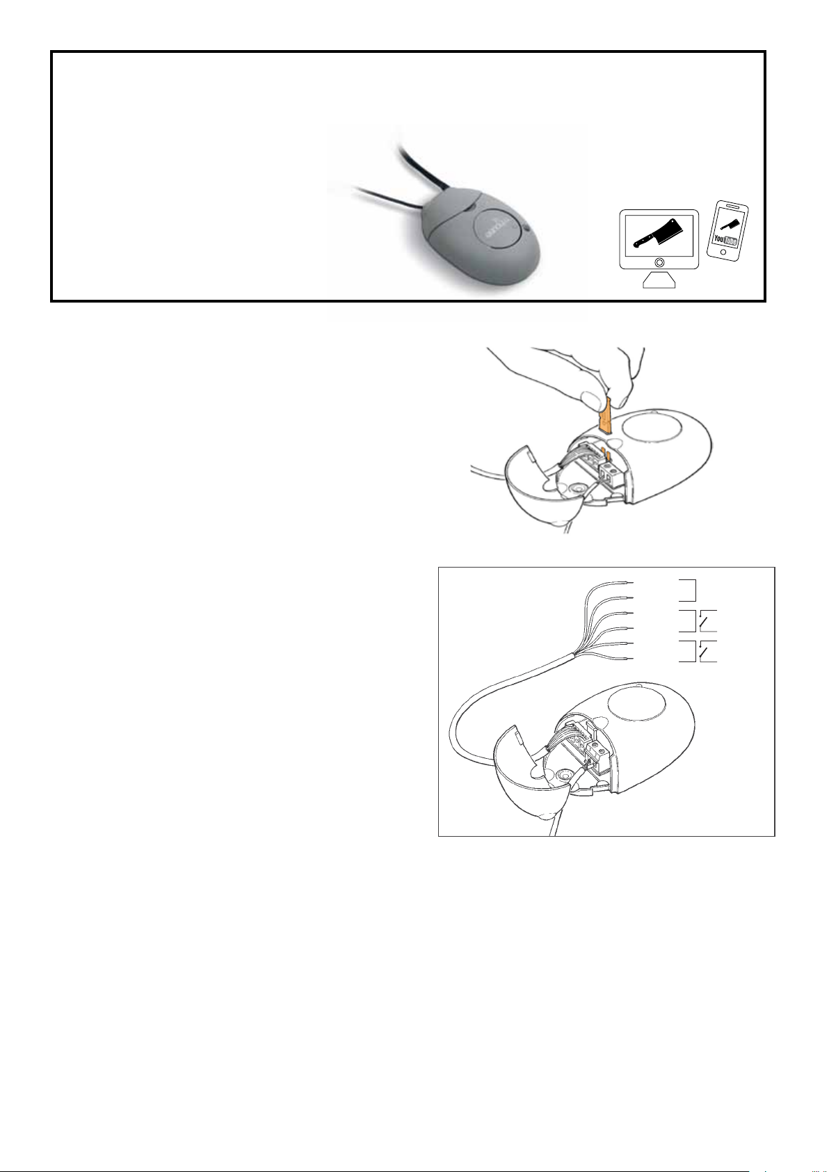
AERIAL
The aerial is the white wire in terminal
1-2.
The remote’s signal range can be extend-
ed by tting a longer cable or an external
aerial tted outdoors as high as possible.
When using coaxial cable connect the
centre part of the cable to terminal 2, and
the braid to terminal 1. See pic.
1. Presser et maintenir enfoncée la touche P1 sur la logique de commande.
2. Attendre que la LED P1 s’allume puis dans les trois secondes qui suivent:
3. Presser pendant au moins trois secondes la touche de l’émetteur radio à eacer.
Si l’eacement a eu lieu, la LED P1 le conrmera par cinq clignotements rapides.
Si la LED n’eectue qu’un clignotement lent, la phase d’eacement n’a pas eu lieu
parce que l’émetteur n’est pas mémorisé.
4. S’il y a d’autres émetteurs à eacer, tout en continuant à presser la touche P1 ,
répéter le point 3 dans les dix secondes successives, autrement la phase d’ea-
cement se termine automatiquement.
Avec la mémorisation de l’émetteur en “mode 2”, on peut associer à chaque touche
l’une des deux sorties du récepteur radio (voir tableau 4).
En “mode 2”, chaque touche nécessite sa propre phase de mémorisation.
1. Sur le récepteur, presser la touche P1 de la Fig. 4 un nombre de fois égal à la
commande désirée selon le tableau suivant (ex. 2 fois pour la commande “Activa-
tion sortie N°2).
2. Vérier que le LED P1 de la Fig. 4 émet un nombre de clignotements égal à la sor-
tie sélectionnée.
3. Dans les 10 s qui suivent, presser pendant au moins 2 s la touche désirée de
l’émetteur à mémoriser. Si la mémorisation a été eectuée correctement la LED
P1 émettra 3 clignotements.
4. S’il y a d’autres émetteurs à mémoriser pour le même type de commande, répéter
le point 3 dans les 10 s successives, autrement la phase de mémorisation se ter-
mine automatiquement.
Mémorisation à distance
Il est possible de mémoriser un nouvel émetteur sans agir directement sur les
touches du récepteur radio. Il faut disposer d’un “ ANCIEN ” émetteur déjà mémorisé
et fonctionnant.
Le “ NOUVEL ” émetteur à mémoriser “héritera” des caractéristiques de l’ ANCIEN ;
cela signie que si l’ ANCIEN émetteur est mémorisé en “mode 1”, le NOUVEAU
sera mémorisé lui aussi en “mode 1”; dans ce cas, durant la phase de mémorisation,
on peut presser n’importe quelle touche des deux émetteurs.
Si par contre l’ ANCIEN émetteur est mémorisé en “mode 2”, il faudra presser sur
l’ANCIEN , la touche avec la commande désirée, et sur le NOUVEAU la touche à
laquelle on désire associer la commande en question.
Avec les deux émetteurs, se placer dans le rayon d’action de la logique de com-
mande ou du récepteur et eectuer les opérations suivantes:
1. Presser pendant au moins 5 s la touche sur le NOUVEL émetteur, puis relâcher.
2. Presser lentement 3 fois la touche sur l’ ANCIEN émetteur.
3. Presser lentement 1 fois la touche sur le NOUVEL émetteur.
Le NOUVEL émetteur sera alors reconnu par la logique de commande ou par le
récepteur et héritera des caractéristiques de l’ ANCIEN . S’il y a d’autres émetteurs à
mémoriser, répéter tous les points ci-dessus pour chacun d’eux.
Entretien et mise au rebut
Le système n’a besoin d’aucun entretien particulier.
Ce produit est constitué de diérents types de matériaux dont certains peuvent être
recyclés, d’autres devront être mis au rebut. Informez-vous sur les systèmes de
recyclage ou de mise au rebut du produit en respectant les normes locales en
vigueur.
Attention: certains composants électroniques pourraient contenir des substances
polluantes, ne pas les abandonner dans la nature.
Caractéristiques techniques
R2 est produit par NICE S.p.a. (TV) I, MHOUSE S.r.l. est une société du groupe NICE S.p.a.
Dans le but d’améliorer les produits, NICE S.p.a. se réserve le droit d’en modier à tout moment et
sans préavis les caractéristiques techniques, en garantissant dans tous les cas le bon fonctionne-
ment et le type d’utilisation prévus.
N.B.: toutes les caractéristiques techniques se réfèrent à la température de 20°C. Le présent pro-
duit est compatible avec les émetteurs mod. TX3 et TX4.
Typologie: Récepteur radio pour le contrôle d’automatismes pour portails; portes
automatiques et similaires Technologie adoptée: Réception et décodage des
signaux radio émis par les émetteurs. Activation des re lais de sortie seulement en
cas de correspondance d’un code préalablement mémorisé et correctement en syn-
chronisme Possibilité de télécommande: Avec émetteurs GTX4 Codage:
Rolling code avec code à 64 bits (18 milliards de milliards de combinaisons) Émet-
teurs GTX4 mémorisables: jusqu’à 256 s’ils sont mémorisés en mode 1 Fré-
quence de réception: 433,92 MHz Entrée antenne radio: 52 ohms pour câble
type RG58 ou similaires Longueur maximum câble antenne : Moins de 5m
Sensibilité du récepteur: Supérieure à 0,5µV Portée des émetteurs GTX4: Esti-
mée à 50-100m (la portée varie en présence d’obstacles et de parasites électroma-
gnétiques et elle est inuencée par la position de l’antenne) Alimentation: sans
connexion volante: 24V typiques (18÷35Vcc, 15÷28Vca) , avec connexion volante:
12V typiques (10÷18 Vcc, 9÷15Vca) Absorption au repos: 10 mA (typiques à
24Vca) Absorption avec 1 relais actif: 50 mA (maximum à 24Vca) Relais de
sortie: 2 avec contact relais normalement ouvert Caractéristiques contact
relais: Maximum 50V et 0,3A Temps d’activation: environ 200ms Temps de
désactivation: environ 300 ms Température ambiante de fonctionnement: -10
÷ 55°C Utilisation en atmosphère acide, saline ou po tentiellement explosive:
Non Indice de protection: IP 30D (utilisation dans des lieux protégés) Dimen-
sions / poids: 86 x 57xh 22mm, poids 55g
Avertissements
•Avant de commencer l’installation, vérier si le récepteur est adapté à l’emploi, en
faisant particulièrement attention aux données gurant dans le chapitre “Caracté-
ristiques techniques”; MHOUSE ne répond pas des dommages résultant d’une
utilisation du produit diérente de celle qui est prévue dans le présent manuel.
•Éviter que le récepteur puisse se mouiller, ne pas le conserver à proximité de
sources de chaleur ni l’exposer à des ammes; si cela se produit, suspendre
immédiatement l’utilisation et s’adresser au service après-vente MHOUSE.
•Pour les opérations d’installation, couper l’arrivée de l’alimentation électrique.
Description et application
Le récepteur R2, associé aux émetteurs GTX4, permet de commander à distance
des appareils électriques comme par exemple des logiques de commande pour por-
tails ou automatismes similaires; il dispose de 2 sorties avec contact à relais norma-
lement ouvert “NO”. Quand l’émetteur envoie un “signal” qui est reconnu comme
valable, le récepteur provoque l’activation du relais de sortie correspondant (le
contact se ferme). Le relais se désactivera dès que l’émetteur arrête l’envoi du signal
radio. Le présent produit est compatible avec les émetteurs mod. TX3 et TX4.
Installation
Récepteur
Le récepteur R2 permet une utilisation universelle. Le boîtier fournit une
protection essentielle et ecace au circuit; il peut être xé avec l’adhésif sur le fond.
Sélection de l’alimentation
La tension d’alimentation du récepteur est de 24 V; il est possible d’alimenter R2
également à 12 V en plaçant la connexion volante comme l’indique la Fig. 1.
Connexions électriques
Les connexions du récepteur sont eectuées à l’aide de ls de diérentes couleurs
(Fig. 2)
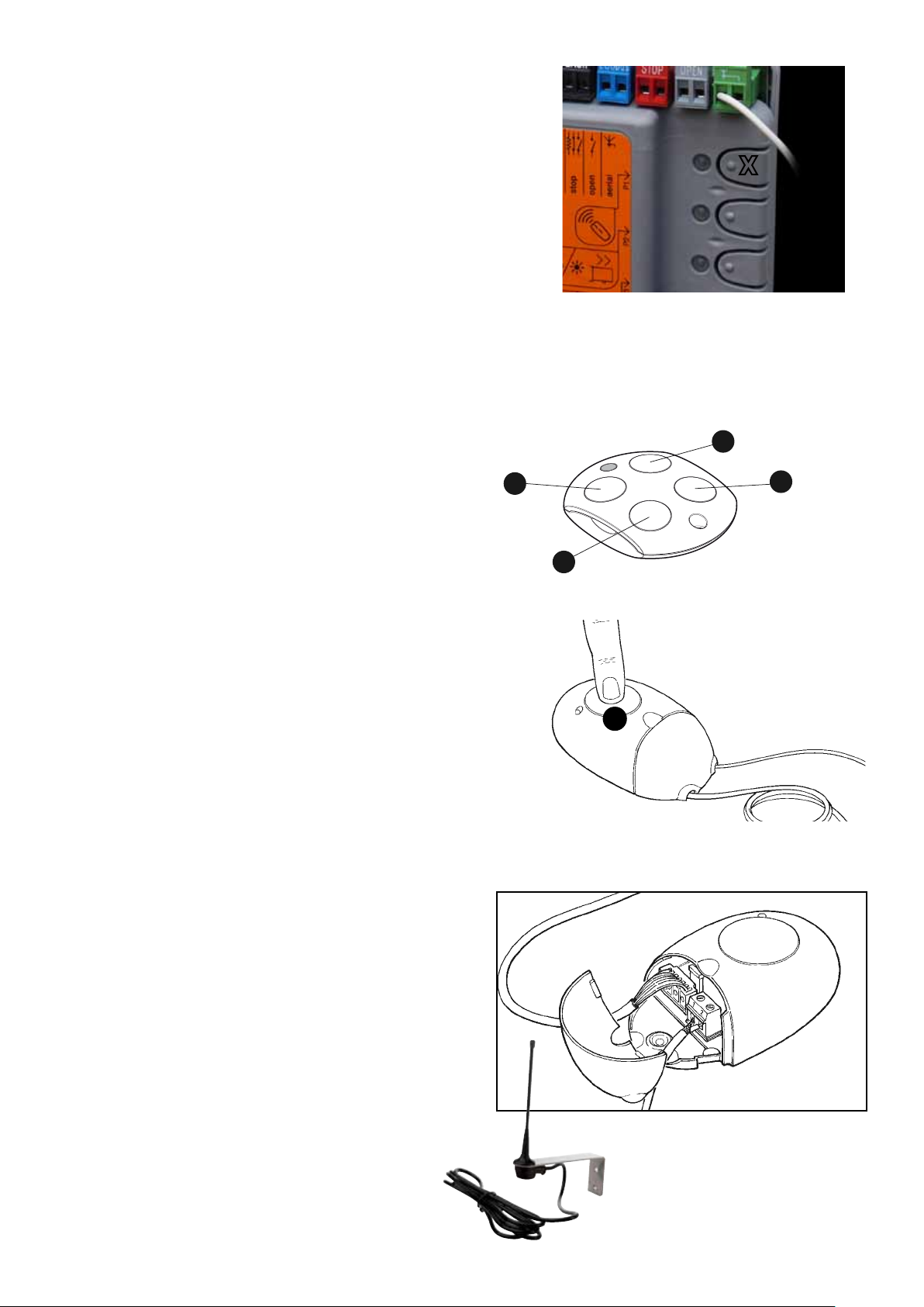
Antenne
Le récepteur R2 est déjà muni d’une antenne interne (le bout de l déjà connecté à
la borne 2); pour obtenir de meilleures performances, il est possible de connecter
une antenne extérieure, par exemple celle qui est présente dans le clignotant FL100
Mhouse. L’antenne doit être installée le plus haut possible, jamais en dessous mais
éventuellement au-dessus de structures métalliques ou en béton armé qui pour-
raient créer un blindage. Utiliser un câble coaxial, par exemple RG58, de 5 m de long
maximum. Connecter l’âme du câble à la borne 2 et le conducteur extérieur à la
borne 1.
Mémorisation de l’émetteur
Pour qu’un émetteur puisse commander le récepteur, il faut eectuer une phase de
mémorisation.
Pour mémoriser le nouvel émetteur, il y a deux choix possibles:
•Mode 1: dans ce “mode” l’émetteur radio est utilisé intégralement, c’est-à-dire
que toutes les touches exécutent la commande de la sortie correspondante.
En “mode 1”, les commandes attribuées aux 4 touches (Fig. 3) sont:
•Mode 2: dans ce “mode” à chaque touche de l’émetteur peut être associée l’une
des 2 sorties du récepteur. En utilisant de manière opportune ce mode, avec le
même émetteur GTX4, on peut commander 2 récepteurs diérents ou plus; par
exemple la touche T1 active la sortie N°1 sur le récepteur A; la touche T2 active la
sortie N°1 sur le récepteur B; la touche T3 active la sortie N°2 sur le récepteur A;
la touche T4 active la sortie N°1 sur le récepteur C.
Naturellement, la mémorisation de chaque émetteur est un cas en soi et dans le
même récepteur on peut avoir des émetteurs mémorisés en “mode 1” et d’autres en
“mode 2”.
Attention: vu que l’on dispose pour les procédures de mémorisation d’un maximum
de 10 secondes pour chaque phase, il faut lire au préalable les instructions gurant
dans le paragraphe successif puis procéder à leur exécution.
Mémorisation de l’émetteur en “mode 1”
1. Sur le récepteur, presser la touche P1 de la Fig. 4 pendant au moins 3 s; quand la
LED P1 s’allume, relâcher la touche.
2. Dans les 10 s qui suivent, presser pendant au moins 2 s une touche quelconque
de l’émetteur à mémoriser. Si la mémorisation a été eectuée correctement la
LED P1 émettra 3 clignotements.
3. S’il y a d’autres émetteurs à mémoriser, répéter le point 2 dans les 10 s succes-
sives, autrement la phase de mémorisation se termine automatiquement.
Mémorisation de l’émetteur en “mode 2”
Eacer la télécommande en eectuant la procédure.
TABLEAU 2
TABLEAU 1
Avvertenze
•Prima di iniziare l’installazione vericate se il ricevitore è adatto all’uso, con partico-
lare attenzione ai dati riportati nel capitolo "Caratteristiche tecniche"; MHOUSE
non risponde dei danni risultanti da un uso del prodotto diverso da quanto previsto
nel presente manuale.
•Evitare che il ricevitore possa bagnarsi, non tenerlo vicino a forti fonti di calore né
esporlo a amme; qualora accada, sospendere immediatamente l’uso e rivolgersi
al servizio assistenza MHOUSE.
•Le operazioni di installazione devono avvenire senza la presenza dell’alimentazione
elettrica.
Descrizione e destinazione d’uso
Il ricevitore R2, in abbinamento ai trasmettitori GTX4 consente di comandare a
distanza apparecchi elettrici come, ad esempio, centrali di comando per cancelli o
automazioni similari; dispone di 2 uscite con contatto a relè normalmente aperto
“NA”. Quando il trasmettitore invia un “segnale” che viene riconosciuto come valido,
il ricevitore provoca l’attivazione del corrispondente relè di uscita (il contatto si chiu-
de). Il relè si disattiverà non appena il trasmettitore smette di inviare il segnale radio.
Il presente prodotto è compatibile con i trasmettitori mod. TX3 e TX4.
Installazione
Ricevitore
Il ricevitore R2 permette un uso universale. Il contenitore fornisce una protezione
essenziale ed ecace al circuito; può essere ssato con l’adesivo sul fondo.
Selezione dell’alimentazione
La tensione di alimentazione del ricevitore è di 24V; è possibile alimentare R2 anche
a 12V inserendo l’apposito ponticello come indicato in Fig.1.
Collegamenti elettrici
Il ricevitore prevede i collegamenti mediante dei conduttori con diversa colorazione
(Fig.2).
Antenna
Il ricevitore R2 è già corredato di antenna interna (lo spezzone di lo già collegato al
morsetto 2); per ottenere migliori prestazioni è possibile collegare un’antenna ester-
na, ad esempio quella presente nel lampeggiante FL100 Mhouse.
L’antenna deve essere installata più in alto possibile, mai sotto ma eventualmente
sopra a strutture metalliche o di cemento armato che potrebbero schermarla. Utiliz-
zare cavo coassiale, esempio RG58, lungo al massimo 5m. Collegare la parte cen-
trale del cavo al morsetto 2 e la calza al morsetto 1.
Memorizzazione del trasmettitore
Anché un trasmettitore possa comandare il ricevitore, è necessario eseguire una
fase di memorizzazione.
Per memorizzare il nuovo trasmettitore vi sono due scelte possibili:
•Modo 1: in questo “modo” il trasmettitore radio è usato per intero cioè tutti i tasti
eseguono il comando dell’uscita corrispondente.
In “modo 1”, comandi attribuiti ai 4 tasti (Fig. 3) sono:
•Modo 2: in questo “modo” ad ogni tasto del trasmettitore può essere associata
una delle 2 uscite del ricevitore. Usando opportunamente questa modalità, con lo
stesso trasmettitore GTX4 è possibile comandare 2 o più ricevitori diversi; ad
esempio il tasto T1 attiva uscita N° 1 su ricevitore A; il tasto T2 attiva uscita N° 1
su ricevitore B; il tasto T3 attiva uscita N° 2 su ricevitore A; tasto T4 attiva uscita N°
1 su ricevitore C.
Naturalmente la memorizzazione di ogni trasmettitore fa caso a se e nello stesso
ricevitore ve ne possono essere memorizzati alcuni in “modo 1” altri in “modo 2”.
Attenzione: poiché le procedure di memorizzazione sono a tempo (massimo 10
secondi per ogni fase), è necessario leggere prima le istruzioni riportate nel paragrafo
successivo e poi procedere con l’esecuzione delle stesse.
Memorizzazione del trasmettitore in “modo 1”
1. Sul ricevitore premere il Tasto P1 di Fig.4 per almeno 3s; quando il LED P1 si
accende, rilasciare il tasto.
2. Entro 10s premere per almeno 2s un tasto qualsiasi del trasmettitore da memoriz-
zare. Se la memorizzazione è andata a buon ne il LED P1 farà 3 lampeggi.
3. Se ci sono altri telecomandi da memorizzare, ripetere il passo 2 entro altri 10s altri-
menti la fase di memorizzazione terminerà automaticamente.
Memorizzazione del trasmettitore in “modo 2”
Cancellare il telecomando eseguendo la procedura.
1. Premere e tenere premuto il tasto P1 sulla centrale.
2. Attendere che il LED P1 si accenda, quindi entro tre secondi:
3. Premere per almeno tre secondi il tasto del trasmettitore radio da cancellare. Se la
TABELLA 1
TABELLA 2
TABLE 1
Warnings
•Before you start installing the receiver, make sure it is suitable for its intended pur-
pose; pay special attention for the data provided in the “Technical Characteristics”
chapter. MHOUSE disclaims responsibility for any damage resulting from improper
use of the product; the only use authorized by the manufacturer is the one
described in this manual.
•Protect the receiver from water and other liquids and do not place it near heat
sources or expose it to open ames;if this should occur, stop using it immediately
and call MHOUSE customer service;
•All the installation operations must be performed while the devices are disconnect-
ed from the power supply.
Description and Intended Use
The R2 receiver, used in combination with the GTX4 transmitters, is suitable for the
remote control of electrical equipment such as gate control units and similar automa-
tions; The receiver has two outputs with normally open (NO) relay contact. When the
transmitter sends a signal that is recognized as valid, the receiver causes the activa-
tion of the corresponding output relay (the contact closes). The relay will deactivate
as soon as the transmitter stops sending the radio signal. This product is compatible
with transmitter models TX3 and TX4.
Installation
Receiver
The R2 receiver enables universal use. The casing provides essential and ecient
protection to the circuit. It can be secured with the adhesive on the bottom.
Selecting the power supply
The receiver’s power supply is 24V (both direct and alternate current). However, R2
can also be connected to a 12V power source. To do this, just insert the jumper
shown in Fig.1.
Electrical connections
The receiver is connected through colour-coded conductors (Fig.2).
Aerial
The R2 receiver is equipped with an internal aerial (the length of wire just connected
to terminal 2). However, in order to obtain a better performance it can be connected
to an external aerial (for example, the one found on the FL100 ashing light by
Mhouse).
The aerial should be installed as high as possible, never under but eventually over
metal or concrete structures which could blind it. Use coaxial cable (RG58, for exam-
ple) with a maximum length of 5m. Connect the centre part of the cable to terminal
2, and the braid to terminal 1.
Memorizing the transmitter
To enable the transmitter to command a receiver, a memorization procedure must be
carried out.
Two methods can be followed to memorize the new transmitter:
•Mode 1: in this “mode” the radio transmitter is used to its fullest extent, i.e. all the
buttons carry out the command associated to the corresponding output.
In “mode 1”, the commands associated to the 4 buttons (Fig. 3) are the following:
•Mode 2: in this “mode”, each transmitter button can be associated to one of the
two receiver outputs. If this mode is used properly, it will be possible to command
2 or more dierent receivers using the same GTX4 transmitter; for example: But-
ton T1 activates output No. 1 on receiver A; button T2 activates output No. 1 on
reciver B; button T3 activates output No. 2 on reciver A; button T4 activates out-
put No. 1 on reciver C.
Each transmitter is, of course, a separate unit, and while some are memorized in
“mode 1” others can be memorized in “mode 2” on the same receiver.
Warning: since the memorization procedures are timed (max. 10 seconds for each
stage), you need to read the instructions in the following paragraph before you pro-
ceed to carry them out.
Memorizing the transmitter in “mode 1”
1. Press button P1 Fig.4 on the receiver for at least 3s; when the P1 LED lights up,
release the button.
2. Within 10s, press any button on the transmitter to be memorized for at least 2s. If
the memorization procedure is successful, the P1 LED will ash 3 times.
3. If there are other remote controls to be memorized, repeat step 2 within the next
10s, otherwise the memorization stage will terminate automatically.
Memorizing the transmitter in “mode 2”
Delete the remote control system by following procedure
1. Press and hold down button P1 on the control unit.
2. Wait until the P1 LED lights up, then, within three seconds:
TABLE 2
Mhouse R2
Photocells
EN Installation and use
instruc tions and warnings
IT Istruzioni ed avvertenze
per l’installazione e l’uso
FR Instructions et avertisse-
ments pour l’installation et
l’utilisation
ES Instrucciones y adverten-
cias para la instalación y el
uso
DE Anweisungen und Hinwei-
se für die Installation und
die Bedienung
PL Instrukcje instalacji i użyt-
kowania i ostrzeżeni
NL Aanwijzingen en aanbeve-
lingen voor installering en
gebruik
IS0033A00MM
23-02-2011
Mhouse is a commercial trademark
owned by Nice S.p.a.
cancellazione è avvenuta il LED P1 farà cinque lampeggi veloci. Se il LED P1
dovesse fare 1 lampeggio lento la fase di cancellazione non è avvenuta perché il
trasmettitore non è memorizzato.
4. Se ci sono altri trasmettitori da cancellare, sempre con il tasto P1 premuto, ripete-
re il passo 3 entro dieci secondi, altrimenti la fase di cancellazione termina auto-
maticamente.
Con la memorizzazione del trasmettitore in “modo 2”, ad ogni tasto può essere
associata una qualsiasi tra le due uscite del ricevitore radio (vedere tabella 4).
In “modo 2” ogni tasto richiede una propria fase di memorizzazione.
1. Sul ricevitore premere il Tasto P1 di Fig.4 un numero di volte pari al comando
desiderato, secondo la seguente tabella (es. 2 per “Attivazione uscita N°2):
2. Vericare che il LED P1 di Fig.4 emetta un numero di lampeggi pari all’uscita sele-
zionata.
3. Entro 10 s premere per almeno 2 s il tasto desiderato del trasmettitore da memo-
rizzare. Se la memorizzazione è andata a buon ne il LED P1 farà 3 lampeggi.
4. Se ci sono altri telecomandi da memorizzare per lo stesso tipo di comando, ripe-
tere il passo 3 entro altri 10 s, altrimenti la fase di memorizzazione termina auto-
maticamente.
Memorizzazione a distanza
È possibile memorizzare un nuovo trasmettitore senza agire direttamente sui tasti
della ricevente radio. È necessario disporre di un trasmettitore già memorizzato e
funzionante “VECCHIO ”.
Il trasmettitore da memorizzare NUOVO prenderà in “erediterà” le caratteristiche di
quello VECCHIO ; quindi se il VECCHIO trasmettitore è memorizzato in “modo 1”
anche il NUOVO verrà memorizzato in “modo 1”; in questo caso durante la fase di
memorizzazione può essere premuto un tasto qualunque nei due trasmettitori.
Se invece il VECCHIO trasmettitore è memorizzato in “modo 2” occorrerà premere
nel VECCHIO il tasto col comando desiderato, e nel NUOVO il tasto al quale si vuole
associare quel comando.
Con i due trasmettitori porsi nelle vicinanze della centrale o del ricevitore ed eseguire
le seguenti fasi:
1. Premere per almeno 5s il tasto sul NUOVO trasmettitore, poi rilasciare.
2. Premere lentamente per 3 volte il tasto sul VECCHIO trasmettitore.
3. Premere lentamente per 1 volta il tasto sul NUOVO trasmettitore.
A questo punto il trasmettitore NUOVO verrà riconosciuto dalla centrale o dal ricevi-
tore e prenderà le caratteristiche che aveva quello VECCHIO
Se ci sono altri trasmettitori da memorizzare, ripetere tutti i passi per ogni nuovo tra-
smettitore.
Manutenzione e Smaltimento
Il sistema non necessita di alcuna manutenzione particolare.
Questo prodotto è costituito da varie tipologie di materiali, alcuni possono essere
riciclati, altri dovranno essere smaltiti. Informatevi sui sistemi di riciclaggio o smalti-
mento del prodotto attenendosi alle norme di legge vigenti a livello locale.
Attenzione: alcuni componenti elettronici potrebbero contenere sostanze inquinanti:
non disperdeteli nell’ambiente.
Caratteristiche tecniche
R2 è prodotto da NICE S.p.a. (TV) I, MHOUSE S.r.l. è una società del gruppo NICE S.p.a.
Allo scopo di migliorare i prodotti, NICE S.p.a. si riserva il diritto di modicare le caratteristiche tec-
niche in qualsiasi momento e senza preavviso, garantendo comunque funzionalità e destinazione
d’uso previste.
Nota: tutte le caratteristiche tecniche sono riferite alla temperatura di 20°C. Il presente prodotto è
compatibile con i trasmettitori mod. TX3 e TX4.
Tipologia: Ricevitore radio per il controllo di automatismi per cancelli; portoni
automatici e similari Tecnologia adottata: Ricezione e decodica dei segnali radio
emessi dai trasmettitori. Attivazione dei relè di uscita solo in caso di corrispondenza
di un codice precedentemente memorizzato e correttamente in sincronismo con la
sequenza di variabilità Possibilità di telecomando: Con trasmettitori GTX4
Codica: Rolling code con codice a 64 Bit (18 miliardi di miliardi di combinazioni)
Trasmettitori GTX4 memorizzabili: Fino a 256 se memorizzati in modo 1 Fre-
quenza di ricezione: 433.92 Mhz Ingresso antenna radio: 52 ohm per cavo tipo
RG58 o simili Lunghezza massima cavo antenna: Minore di 5m Sensibilità
del ricevitore: Migliore di 0.5µV Portata dei trasmettitori GTX4: Stimata in 50-
100m (la portata cambia in presenza di ostacoli e di disturbi elettromagnetici ed è
inuenzata dalla posizione dell’antenna) Alimentazione: senza ponticello: 24V
tipici (18÷35Vdc, 15÷28Vac) , con ponticello: 12V tipici (10÷18Vdc, 9÷15 Vac)
Assorbimento a riposo: 10mA (tipici a 24Vac) Assorbimento con 1 relè attivo:
50mA (massimi a 24Vac) Relè di uscita: N°2 con contatto relè normalmente aper-
to Caratteristiche contatto relè: Massimo 50V e 0.3A Tempo attivazione: cir-
ca 200ms Tempo disattivazione: circa 300ms Temperatura ambientale di
funzionamento: -10 ÷ 55°C Utilizzo in atmosfera acida, salina o potenzial-
mente esplosiva: No Grado di protezione: IP30D (utilizzo in ambienti protetti)
Dimensioni / peso: 86x57xh22mm, peso 55g
ITALIANO
Istruzioni originali
FRANÇAIS
Instructions originales
3. Press and hold down for at least three seconds the button of the radio transmitter
to be deleted.If the radio transmitter has been deleted, the P1 LED will ash quick-
ly ve times. If the LED ashes slowly just once, it means that the deletion has not
taken place because the transmitter is not memorized
4. If there are more transmitters to be deleted, repeat step 3 within ten seconds while
pressing button P1 , otherwise the deletion stage will terminate automatically.
With the memorization of the transmitter in “mode 2”, each button can be associated
to any of the two radio receiver outputs (see table 4).
In “mode 2”, each button requires a separate memorization stage.
1. Press button P1 Fig.4 on the receiver as many times as the number correspon-
ding to the desired command, according to the following table (e.g. 2 times for
“Activation of output N. 2”):
2. Make sure that the P1 LED Fig.4 ashes as many times as the number of the
selected output.
3. Within 10 s, press the desired button on the transmitter to be memorized, and
hold it down for at least 2s. If the memorization procedure is successful, the P1
LED will ash 3 times.
4. If there are other remote controls to be memorized for the same type of command,
repeat step 3 within the next 10s, otherwise the memorization stage will terminate
automatically.
Remote memorisation
It is possible to memorize a new transmitter without directly operating the buttons on
the radio receiver, provided you have an “ OLD ” pre-memorized operational transmit-
ter.
The NEW transmitter to be memorized will inherit the characteristics of the OLD one,
i.e. if the OLD transmitter was memorized in “mode 1”, the NEW one will also be
memorized in “mode 1”. In this case, during the memorization stage you can press
any key on the two transmitters.
If, on the other hand, the OLD transmitter was memorized in “mode 2” you must
press the button on the OLD transmitter which corresponds to the desired com-
mand, and the button on the NEW transmitter to which you wish to associate that
command.
Holding the two transmitters, position yourself near the control unit or receiver and
perform the following operations:
1. Press the button on the NEW transmitter and hold it down for at least 5s, then
release it.
2. Press the button on the OLD transmitter 3 times slowly.
3. Press the button on the NEW transmitter once slowly.
At this point the NEW transmitter will be recognized by the control unit or receiver
and will assume the characteristics of the OLD one.
If there are other transmitters to be memorized, repeat all the steps above for each
new transmitter.
Maintenance and Disposal
The system does not require any special maintenance.
This product is constructed of various types of materials, some of which can be
recycled while others must be disposed of. Make sure you recycle or dispose of the
product in compliance with the laws and regulations locally in force.
Warning: Some electric components may contain polluting substances; do not pol-
lute the environment.
Technical characteristics
R2 is produced by NICE S.p.a. (TV) I, MHOUSE S.r.l. is an aliate of the Nice S.p.a. group.
Nice S.p.a., in order to improve its products, reserves the right to modify their technical character-
istics at any time without prior notice. In any case, the manufacturer guarantees their functionality
and tness for the intended purposes.
Note: all the technical characteristics refer to a temperature of 20°C. This product is compatible
with transmitter models TX3 and TX4.
Type: Radio receiver for control of automatic gates, garage doors and similar
automations Technology adopted: Reception and decoding of the radio signals
emitted by the transmitters. Activation of the output relays only in case of correspon-
dence with a previously memorized code, correctly synchronized with the variability
sequence Possibility of remote control: With GTX4 transmitter Coding: 64 bit
rolling code (18 billion billion combinations) GTX4 transmitter memorization
capacity: Up to 256, if memorized in mode 1 Reception frequency: 433.92 Mhz
Radio aerial input: 52 ohm for RG58 or similar type of cable Maximum length
of aerial cable: up to 5 m Receiver sensitivity: Better than 0.5µV Range of
GTX4 transmitters: Estimated at 50-100m: (this distance may vary in the presence
of obstacles or electromagnetic disturbances and depends on the position of the
receiving aerial) Power supply: Without jumper: 24V typical (18÷35Vdc,
15÷28Vac), With jumper: 12V typical (10÷18Vdc, 9÷15 Vac) Absorption when
idle: 10mA (typical at 24Vac) Absorption with 1 relay active: 50mA (maximum at
24Vac) Output relay: No. 2 with normally open relay contact Relay contact
characteristics: Maximum 50V and 0.3A Activation time: Approx. 200ms
Deactivation time: Approx. 300ms Operating ambient temperature: -10 ÷
55°C Use in acid, saline or potentially explosive atmosphere: No Protec-
tion class: IP30D (use in protected environments) Dimensions / weight:
86x57xh22mm, weight 55g
ENGLISH
Original instructions
1
RED
BLACK
+ (~)
- (~)
WHITE
WHITE
VIOLET OUTPUT 2
OUTPUT 1
24V
ac/dc
VIOLET
Red/Black
White/White
Violet/Violet
Terminals 1, 2
POWER SUPPLY
1st RELAY OUTPUT
2nd RELAY OUTPUT
AERIAL input
Red = Positive, Black = Negative (with alter-
nate current it makes no dierence)
Clean contact of a normally open relay
Clean contact of a normally open relay
Aerial (terminal 1=braid, terminal 2= core)
TABLE
Transmitter
Button T1
Button T2
Button T3
Button T4
Radio receiver
Activation of output relay No.1
Activation of output relay No.2
Not used
Not used
TABLE 4
Button P1
1 time
2 times
3 times
4 times
Radio receiver
Activation of output No.1
Activation of output No.2
Not used
Not used
Rosso/Nero
Bianco/Bianco
Viola/Viola
Morsetti 1, 2
ALIMENTAZIONE
USCITA 1° RELÉ
USCITA 2° RELÉ
Ingresso ANTENNA
Rosso = Positivo, Nero = Negativo (in cor-
rente alternata è indierente)
Contatto pulito di un relé normalmente aperto
Contatto pulito di un relé normalmente aperto
Antenna
(morsetto 1=calza, morsetto 2= anima)
Ponticello
non inserito
Ponticello inserito
24 V ac/dc
12 V ac/dc
Limiti di tensione: 18÷35Vdc, 15÷28Vac
Limiti di tensione: 10÷18Vdc, 9÷15 Vac
TABELLA 3
Trasmettitore
Tasto T1
Tasto T2
Tasto T3
Tasto T4
Ricevitore radio
Attivazione relè uscita N°1
Attivazione relè uscita N°2
Non utilizzato
Non utilizzato
TABELLA 4
Tasto P1
1 volta
2 volte
3 volte
4 volte
Ricevitore radio
Attivazione uscita N°1
Attivazione uscita N°2
Non utilizzato
Non utilizzato
Jumper
not inserted
Jumper inserted
24 Vac/dc
12 Vac/dc
Voltage limits: 18÷35Vdc, 15÷28Vac
Voltage limits: 10÷18Vdc, 9÷15 Vac
Rouge/Noir
Blanc/Blanc
Violet/Violet
Bornes 1, 2
ALIMENTATION
SORTIE 1 ERELAIS
SORTIE 2 ERELAIS
Entrée ANTENNE
Rouge = Positif, Noir = Négatif (dans le cas du
courant alternatif, c’est indiérent)
Contact à vide d’un relais normalement ouvert
Contact à vide d’un relais normalement ouvert
Antenne (borne 1=conducteur extérieur,
borne 2= âme)
TABLEAU 3
Émetteur
Touches T1
Touches T2
Touches T3
Touches T4
Récepteur radio
Activation relais sortie N°1
Activation relais sortie N°2
Non utilisé
Non utilisé
TABLEAU 4
Touche P1
1 fois
2 fois
3 fois
4 fois
Récepteur radio
Activation sortie N°1
Activation sortie N°2
Non utilisé
Non utilisé
Connexion volante
non activée
Connexion volante
activée
24 Vac/dc
12 Vac/dc
Limites de tension : 18÷35Vdc, 15÷28Vac
Limites de tension : 10÷18Vdc, 9÷15 Vac
T1
T2
T3
T4
EN - CE declaration of conformity
Declaration in accordance with Directive 1999/5/EC
R2 is produced by Nice S.p.a. (TV) I; MHOUSE S.r.l. is a com-
mercial trademark owned by Nice S.p.a.
Note - The contents of this declaration correspond to declara-
tions in the ocial document deposited at the registered oces
of Nice S.p.a. and in particular to the last revision available
before printing this manual. The text herein has been re-edited
for editorial purposes. A copy of the original declaration can be
requested from Nice S.p.a. (TV) I.
Number of declaration : 274/R2 Revision : 3
Language : IT
The undersigned, Luigi Paro, in the role of Manag-
ing Director, declares under his sole responsibility,
that the product:
Manufacturer’s Name: NICE S.p.A. - Address:
Via Pezza Alta n°13, 31046 Rustignè di Oderzo
(TV) Italy - Product type: Receiver 433MHz -
Model / Type: R2 - Accessories: -
Conforms to the essential requirements stated in
article 3 of the following EC directive, for the
intended use of products:
•Directive 1999/5/EC OF THE EUROPEAN PAR-
LIAMENT AND COUNCIL of 9 March 1999 regard-
ing radio equipment and telecommunications ter-
minal equipment and the mutual recognition of
their conformity according to the following har-
monised standards:
- Health protection (art. 3(1)(a)): EN 50371:2002
- Electrical safety (art. 3(1)(a)): EN 60950-1:2006+A11:2009
- Electromagnetic compatibility (art. 3(1)(b)): EN 301 489-1
V1.8.1:2008, EN 301 489-3 V1.4.1:2002
- Radio spectrum (art. 3(2)): EN 300 220-2 V2.1.2:2007
Oderzo, 11 February 2011
Ing. Luigi Paro (Managing Director)
IT - Dichiarazione CE di conformità
Dichiarazione in accordo alla Direttiva 1999/5/CE
R2 è prodotto prodotto da NICE S.p.a. (TV) I; MHOUSE S.r.l.
è un marchio commerciale del gruppo Nice S.p.a
Nota - Il contenuto di questa dichiarazione corrisponde a
quanto dichiarato nel documento uciale depositato presso la
sede di Nice S.p.a., e in particolare, alla sua ultima revisione
disponibile prima della stampa di questo manuale. Il testo qui
presente è stato riadattato per motivi editoriali. Copia della
dichiarazione originale può essere richiesta a Nice S.p.a. (TV) I.
Numero dichiarazione : 274/R2 Revisione : 3
Lingua : IT
Il sottoscritto Luigi Paro in qualità di Amministrato-
re Delegato, dichiara sotto la propria responsabili-
tà che il prodotto:
Nome produttore: NICE S.p.A. - Indirizzo: Via
Pezza Alta n°13, 31046 Rustignè di Oderzo (TV)
Italy - Tipo di prodotto: Ricevitore 433MHz -
Modello / Tipo: R2 - Accessori: -
Risulta conforme ai requisiti essenziali richiesti
dall’articolo 3 della seguente direttiva comunitaria,
per l’uso al quale i prodotti sono destinati:
•Direttiva 1999/5/CE DEL PARLAMENTO EURO-
PEO E DEL CONSIGLIO del 9 marzo 1999 riguar-
dante le apparecchiature radio e le apparecchiatu-
re terminali di comunicazione e il reciproco ricono-
scimento della loro conformità, secondo le se -
guenti norme armonizzate:
- Protezione della salute (art. 3(1)(a)): EN 50371:2002
- Sicurezza elettrica (art. 3(1)(a)): EN 60950-1:2006+A11:2009
- Compatibilità elettromagnetica (art. 3(1)(b)):
EN 301 489-1 V1.8.1:2008, EN 301 489-3 V1.4.1:2002
- Spettro radio (art. 3(2)): EN 300 220-2 V2.1.2:2007
Oderzo, 11 febbraio 2011
Ing. Luigi Paro (Amministratore Delegato)
FR - Déclaration CE de conformité
Déclaration en accord avec la directive 1999/5/CE
R2 est produit par Nice S.p.a. (TV) I ; MHOUSE S.r.l. est une
marque commerciale du groupe Nice S.p.a.
Note - Le contenu de cette déclaration de conformité corres-
pond à ce qui est déclaré dans le document ociel, déposé au
siège de Nice S.p.a., et en particulier à sa dernière révision dis-
ponible avant l’impression de ce guide. Ce texte a été réadapté
pour des raisons d’édition. Une copie de la déclaration origi-
nale peut être demandée à Nice S.p.a. (TV) I.
Numéro déclaration : 274/R2 Révision : 3
Langue : FR
Le soussigné Luigi Paro en tant qu’Administrateur
Délégué déclare sous sa propre responsabilité que
le produit :
Nom producteur : NICE S.p.A. - Adresse : Via
Pezza Alta n°13, 31046 Rustignè di Oderzo (TV)
Italy - Type de produit : Récepteur 433MHz -
Modèle / Type : R2 - Accessoires : -
Est conforme aux critères essentiels requis par
l’article 3 de la directive communautaire suivante,
pour l’usage auquel ces produits sont destinés :
•DIRECTIVE 1999/5/CE DU PARLEMENT EURO-
PÉEN ET DU CONSEIL du 9 mars 1999 concer-
nant les équipements hertziens et les équipements
terminaux de télécommunication et la reconnais-
sance mutuelle de leur conformité, selon les
normes harmonisées suivantes :
- Protection de la santé (art. 3(1)(a)) : EN 50371:2002
- Sécurité électrique (art. 3(1)(a)) : EN 60950-1:2006+A11:2009
- Compatibilité électromagnétique (art. 3(1)(b)) :
EN 301 489-1 V1.8.1:2008, EN 301 489-3 V1.4.1:2002
- Spectre radio (art. 3(2)) : EN 300 220-2 V2.1.2:2007
Oderzo, le 11 février 2011
Ing. Luigi Paro (Administrateur Délégué)
ES - Declaración de conformidad CE
Declaración de acuerdo con la Directiva 1999/5/CE
R2 es fabricado por NICE S.p.a. (TV) I; MHOUSE es una mar-
ca comercial del grupo Nice S.p.a.
Nota - El contenido de esta declaración corresponde a aquello
declarado en el documento ocial depositado en la sede de
Nice S.p.a., y en particular, a su última revisión disponible
antes de la impresión de este manual. El presente texto ha sido
readaptado por motivos de impresión. La copia de la declara-
ción original puede solicitarse a Nice S.p.a. (TV) I.
Número de declaración: 274/R2 Revisión: 3
Idioma: ES
El suscrito, Luigi Paro, en su carácter de Adminis-
trador Delegado, declara bajo su responsabilidad
que el producto:
Nombre del fabricante: NICE S.p.a. - Dirección:
Via Pezza Alta n° 13, 31046 Rustignè di Oderzo
(TV) Italia - Tipo de producto: Receptor 433MHz -
Modelo / Tipo: R2 - Accesorios: -
Es conforme a los requisitos esenciales previstos
por el artículo 3 de la siguiente directiva comunita-
ria, para el uso al cual los productos están desti-
nados:
•Directiva 1999/5/CE DEL PARLAMENTO EURO-
PEO Y DEL CONSEJO del 9 de marzo de 1999
relativa a los equipos radioeléctricos y equipos ter-
minales de telecomunicación y el recíproco reco-
nocimiento de su conformidad, según las siguien-
tes normas armonizadas:
- Protección de la salud [art. 3(1)(a)]: EN 50371:2002
- Seguridad eléctrica [art. 3(1)(a)]: EN 60950-1:2006+A11:2009
- Compatibilidad electromagnética [art. 3(1)(b)]: EN 301 489 1-
V1.8.1:2008, EN 301 489 3-V1.4.1:2002
- Espectro radioeléctrico [art. 3(2)]: EN 300 220-2 V2.1.2:2007
Oderzo, 11 de febrero 2011
Ing. Luigi Paro (Administrador Delegado)
DE - CE Konformitätserklärung
Erklärung in Übereinstimmung mit Richtlinie 1999/5/EG
R2 ist ein Produkt der NICE S.p.a. (TV) I; MHOUSE S.r.l. ist
eine Gesellschaft der Gruppe Nice S.p.a.
Anmerkung - Der Inhalt dieser Erklärung entspricht den Erklä-
rungen des oziellen Dokuments, das im Sitz der Nice S.p.a.
vorliegt, insbesondere hinsichtlich der letzten Überarbeitung
vor dem Druck dieses Handbuchs. Der hier vorliegende Text
wurde aus Herausgebergründen angepasst.
Eine Kopie der ursprünglichen Erklärung jedes Produkts kann
bei Nice S.p.a. (TV) – I - angefordert werden. (TV) I.
Nummer: 274/R2 Revision: 3 Sprache: DE
Der Unterzeichnende Luigi Paro erklärt als Ge -
schäftsführer unter seiner eigenen Verantwortung,
dass das Produkt:
Herstellername: NICE S.p.A. - Adresse: Via Pez-
za Alta n°13, 31046 Z.I. Rustignè, Oderzo (TV) Ita-
lien Typ : Empfänger 433MHz - Modell/Typ : R2 -
Zubehör : -
mit den wichtigsten Anforderungen des Artikels 3
folgender europäischer Richtlinie konform ist, was
den Einsatzzweck der Produkte betrit:
•Richtlinie 1999/5/EGE DES EUROPÄISCHEN
PARLAMENTS UND DES RATS vom 9. März 1999
bezüglich den Funkeinrichtungen und Kommuni-
kationsterminals und der jeweiligen Anerkennung
ihrer Konformität gemäß den folgenden zugehöri-
gen Normen:
- Schutz der Gesundheit (Art. 3(1)(a)) EN 50371:2002
- Elektrische Sicherheit (art. 3(1)(a)): EN 60950-1:2006+A11:2009
- Elektromagnetische Kompatibilität (Art. 3(1)(b)): EN 301 489-
1 V1.8.1:2008, EN 301 489-3 V1.4.1:2002
- Funkspektrum (art. 3(2)): EN 300 220-2 V2.1.2:2007
Oderzo, 11. Februar 2011
Luigi Paro (Geschäftsführer)
PL - Deklaracja zgodności CE
Deklaracja zgodna z Dyrektywą 1999/5/WE
Odbiornik R2 został wyprodukowany przez Nice S.p.a. (TV) I;
MHOUSE S.r.l. jest znakiem handlowym własności grupy Nice S.p.a.
Uwaga - Zawartość niniejszej deklaracji zgodności odpowiada
oświadczeniom znajdującym się w dokumencie urzędowym
złożonym w siedzibie rmy Nice S.p.a., a w szczególności w
ostatniej korekcie dostępnej przed wydrukowaniem tej instruk-
cji. Tekst w niej zawarty został dostosowany w celach wydaw-
niczych. Kopia oryginalnej deklaracji może być zamawiana w
rmie Nice S.p.a. (TV) I.
Numer deklaracji: 274/R2 Wydanie: 3
Język: PL
Niżej podpisany Luigi Paro, w charakterze Członka
Zarządu Spółki oświadcza na własną odpowie-
dzialność, że urządzenie:
Nazwa producenta: NICE S.p.A. - Adres: Via
Pezza Alta nr 13, 31046 Rustignè di Oderzo (TV)
Italy - Typ urządzenia: Odbiornik 433MHz - Mo -
del / Typ: R2 - Urządzenie dodatkowe: -
Jest zgodne z podstawowymi wymogami artykułu
3 niżej zacytowanej dyrektywy europejskiej, pod-
czas użytku, do którego te urządzenia są przezna-
czone:
•Dyrektywa 1999/5/WE PARLAMENTU EURO-
PEJSKIEGO I RADY z dnia 9 marca 1999 roku w
sprawie urządzeń radiowych i końcowych urzą-
dzeń telekomunikacyjnych oraz wzajemnego uz -
nawania ich zgodności, zgodnie z następującymi
normami zharmonizowanymi:
- Zabezpieczenie zdrowia (art. 3(1)(a)): EN 50371:2002
- Bezpieczeństwo elektryczne (art. 3(1)(a)):
EN 60950-1:2006+A11:2009
- Kompatybilność elektromagnetyczna (art. 3(1)(b)):
EN 301 489-1 V1.8.1:2008, EN 301 489-3 V1.4.1:2002
- Widmo radiowe (art. 3(2)): EN 300 220-2 V2.1.2:2007
Oderzo, dnia 11 lutego 2011 roku
Inż. Luigi Paro (Członek Zarządu Spółki)
NL - EG-verklaring van overeenstemming
Verklaring in overeenstemming met 1999/5/EG
R2 wordt geproduceerd door NICE S.p.a. (TV) I, MHOUSE
S.r.l. is een handelsmerk van de groep Nice S.p.a.
Opmerking - De inhoud van deze verklaring stemt overeen met
wat verklaard is in het ociële document dat is neergelegd bij
de vestiging van Nice S.p.a., en in het bijzonder aan de laatste
revisie hiervan die voor het afdrukken van deze handleiding
beschikbaar was. De hier beschreven tekst werd om uitgevers-
redenen heraangepast. U kunt een exemplaar van de originele
verklaring aanvragen bij Nice S.p.a. (TV) I.
Nummer verklaring : 274/R2 Revisie : 3
Taal : NL
Ondergetekende Luigi Paro, in de hoedanigheid
van Gedelegeerd Bestuurder, verklaart onder zijn
eigen verantwoordelijkheid dat het product:
Naam fabrikant: NICE S.p.A. - Adres: Via Pezza
Alta n°13, 31046 Rustignè di Oderzo (TV) Italy -
Producttype: Ontvanger 433MHz - Model / type:
R2 - Accessoires: -
Voldoet aan de fundamentele vereisten opgelegd
door artikel 3 van de volgende communautaire
richtlijn, voor het gebruik waarvoor de producten
bestemd zijn:
•Richtlijn 1999/5/EG VAN HET EUROPEES PAR-
LEMENT EN VAN DE RAAD van 9 maart 1999,
met betrekking tot radioapparatuur en eindappa-
ratuur voor communicatie en de wederzijdse er -
kenning van hun conformiteit, volgens de volgen-
de geharmoniseerde normen:
- Bescherming van de gezondheid (art. 3(1)(a)): EN 50371:2002
- Elektrische veiligheid (art. 3(1)(a)): EN 60950-1:2006+A11:2009
- Elektromagnetische compatibiliteit (art. 3(1)(b)): EN 301 489-
1 V1.8.1:2008, EN 301 489-3 V1.4.1:2002
- Radiospectrum (art. 3(2)): EN 300 220-2 V2.1.2:2007
Oderzo, 11 februari 2011
Ir. Luigi Paro (Gedelegeerd Bestuurder)
P1
1. Presser et maintenir enfoncée la touche P1 sur la logique de commande.
2. Attendre que la LED P1 s’allume puis dans les trois secondes qui suivent:
3. Presser pendant au moins trois secondes la touche de l’émetteur radio à eacer.
Si l’eacement a eu lieu, la LED P1 le conrmera par cinq clignotements rapides.
Si la LED n’eectue qu’un clignotement lent, la phase d’eacement n’a pas eu lieu
parce que l’émetteur n’est pas mémorisé.
4. S’il y a d’autres émetteurs à eacer, tout en continuant à presser la touche P1 ,
répéter le point 3 dans les dix secondes successives, autrement la phase d’ea-
cement se termine automatiquement.
Avec la mémorisation de l’émetteur en “mode 2”, on peut associer à chaque touche
l’une des deux sorties du récepteur radio (voir tableau 4).
En “mode 2”, chaque touche nécessite sa propre phase de mémorisation.
1. Sur le récepteur, presser la touche P1 de la Fig. 4 un nombre de fois égal à la
commande désirée selon le tableau suivant (ex. 2 fois pour la commande “Activa-
tion sortie N°2).
2. Vérier que le LED P1 de la Fig. 4 émet un nombre de clignotements égal à la sor-
tie sélectionnée.
3. Dans les 10 s qui suivent, presser pendant au moins 2 s la touche désirée de
l’émetteur à mémoriser. Si la mémorisation a été eectuée correctement la LED
P1 émettra 3 clignotements.
4. S’il y a d’autres émetteurs à mémoriser pour le même type de commande, répéter
le point 3 dans les 10 s successives, autrement la phase de mémorisation se ter-
mine automatiquement.
Mémorisation à distance
Il est possible de mémoriser un nouvel émetteur sans agir directement sur les
touches du récepteur radio. Il faut disposer d’un “ ANCIEN ” émetteur déjà mémorisé
et fonctionnant.
Le “ NOUVEL ” émetteur à mémoriser “héritera” des caractéristiques de l’ ANCIEN ;
cela signie que si l’ ANCIEN émetteur est mémorisé en “mode 1”, le NOUVEAU
sera mémorisé lui aussi en “mode 1”; dans ce cas, durant la phase de mémorisation,
on peut presser n’importe quelle touche des deux émetteurs.
Si par contre l’ ANCIEN émetteur est mémorisé en “mode 2”, il faudra presser sur
l’ANCIEN , la touche avec la commande désirée, et sur le NOUVEAU la touche à
laquelle on désire associer la commande en question.
Avec les deux émetteurs, se placer dans le rayon d’action de la logique de com-
mande ou du récepteur et eectuer les opérations suivantes:
1. Presser pendant au moins 5 s la touche sur le NOUVEL émetteur, puis relâcher.
2. Presser lentement 3 fois la touche sur l’ ANCIEN émetteur.
3. Presser lentement 1 fois la touche sur le NOUVEL émetteur.
Le NOUVEL émetteur sera alors reconnu par la logique de commande ou par le
récepteur et héritera des caractéristiques de l’ ANCIEN . S’il y a d’autres émetteurs à
mémoriser, répéter tous les points ci-dessus pour chacun d’eux.
Entretien et mise au rebut
Le système n’a besoin d’aucun entretien particulier.
Ce produit est constitué de diérents types de matériaux dont certains peuvent être
recyclés, d’autres devront être mis au rebut. Informez-vous sur les systèmes de
recyclage ou de mise au rebut du produit en respectant les normes locales en
vigueur.
Attention: certains composants électroniques pourraient contenir des substances
polluantes, ne pas les abandonner dans la nature.
Caractéristiques techniques
R2 est produit par NICE S.p.a. (TV) I, MHOUSE S.r.l. est une société du groupe NICE S.p.a.
Dans le but d’améliorer les produits, NICE S.p.a. se réserve le droit d’en modier à tout moment et
sans préavis les caractéristiques techniques, en garantissant dans tous les cas le bon fonctionne-
ment et le type d’utilisation prévus.
N.B.: toutes les caractéristiques techniques se réfèrent à la température de 20°C. Le présent pro-
duit est compatible avec les émetteurs mod. TX3 et TX4.
Typologie: Récepteur radio pour le contrôle d’automatismes pour portails; portes
automatiques et similaires Technologie adoptée: Réception et décodage des
signaux radio émis par les émetteurs. Activation des re lais de sortie seulement en
cas de correspondance d’un code préalablement mémorisé et correctement en syn-
chronisme Possibilité de télécommande: Avec émetteurs GTX4 Codage:
Rolling code avec code à 64 bits (18 milliards de milliards de combinaisons) Émet-
teurs GTX4 mémorisables: jusqu’à 256 s’ils sont mémorisés en mode 1 Fré-
quence de réception: 433,92 MHz Entrée antenne radio: 52 ohms pour câble
type RG58 ou similaires Longueur maximum câble antenne : Moins de 5m
Sensibilité du récepteur: Supérieure à 0,5µV Portée des émetteurs GTX4: Esti-
mée à 50-100m (la portée varie en présence d’obstacles et de parasites électroma-
gnétiques et elle est inuencée par la position de l’antenne) Alimentation: sans
connexion volante: 24V typiques (18÷35Vcc, 15÷28Vca) , avec connexion volante:
12V typiques (10÷18 Vcc, 9÷15Vca) Absorption au repos: 10 mA (typiques à
24Vca) Absorption avec 1 relais actif: 50 mA (maximum à 24Vca) Relais de
sortie: 2 avec contact relais normalement ouvert Caractéristiques contact
relais: Maximum 50V et 0,3A Temps d’activation: environ 200ms Temps de
désactivation: environ 300 ms Température ambiante de fonctionnement: -10
÷ 55°C Utilisation en atmosphère acide, saline ou po tentiellement explosive:
Non Indice de protection: IP 30D (utilisation dans des lieux protégés) Dimen-
sions / poids: 86 x 57xh 22mm, poids 55g
Avertissements
•Avant de commencer l’installation, vérier si le récepteur est adapté à l’emploi, en
faisant particulièrement attention aux données gurant dans le chapitre “Caracté-
ristiques techniques”; MHOUSE ne répond pas des dommages résultant d’une
utilisation du produit diérente de celle qui est prévue dans le présent manuel.
•Éviter que le récepteur puisse se mouiller, ne pas le conserver à proximité de
sources de chaleur ni l’exposer à des ammes; si cela se produit, suspendre
immédiatement l’utilisation et s’adresser au service après-vente MHOUSE.
•Pour les opérations d’installation, couper l’arrivée de l’alimentation électrique.
Description et application
Le récepteur R2, associé aux émetteurs GTX4, permet de commander à distance
des appareils électriques comme par exemple des logiques de commande pour por-
tails ou automatismes similaires; il dispose de 2 sorties avec contact à relais norma-
lement ouvert “NO”. Quand l’émetteur envoie un “signal” qui est reconnu comme
valable, le récepteur provoque l’activation du relais de sortie correspondant (le
contact se ferme). Le relais se désactivera dès que l’émetteur arrête l’envoi du signal
radio. Le présent produit est compatible avec les émetteurs mod. TX3 et TX4.
Installation
Récepteur
Le récepteur R2 permet une utilisation universelle. Le boîtier fournit une
protection essentielle et ecace au circuit; il peut être xé avec l’adhésif sur le fond.
Sélection de l’alimentation
La tension d’alimentation du récepteur est de 24 V; il est possible d’alimenter R2
également à 12 V en plaçant la connexion volante comme l’indique la Fig. 1.
Connexions électriques
Les connexions du récepteur sont eectuées à l’aide de ls de diérentes couleurs
(Fig. 2)
Antenne
Le récepteur R2 est déjà muni d’une antenne interne (le bout de l déjà connecté à
la borne 2); pour obtenir de meilleures performances, il est possible de connecter
une antenne extérieure, par exemple celle qui est présente dans le clignotant FL100
Mhouse. L’antenne doit être installée le plus haut possible, jamais en dessous mais
éventuellement au-dessus de structures métalliques ou en béton armé qui pour-
raient créer un blindage. Utiliser un câble coaxial, par exemple RG58, de 5 m de long
maximum. Connecter l’âme du câble à la borne 2 et le conducteur extérieur à la
borne 1.
Mémorisation de l’émetteur
Pour qu’un émetteur puisse commander le récepteur, il faut eectuer une phase de
mémorisation.
Pour mémoriser le nouvel émetteur, il y a deux choix possibles:
•Mode 1: dans ce “mode” l’émetteur radio est utilisé intégralement, c’est-à-dire
que toutes les touches exécutent la commande de la sortie correspondante.
En “mode 1”, les commandes attribuées aux 4 touches (Fig. 3) sont:
•Mode 2: dans ce “mode” à chaque touche de l’émetteur peut être associée l’une
des 2 sorties du récepteur. En utilisant de manière opportune ce mode, avec le
même émetteur GTX4, on peut commander 2 récepteurs diérents ou plus; par
exemple la touche T1 active la sortie N°1 sur le récepteur A; la touche T2 active la
sortie N°1 sur le récepteur B; la touche T3 active la sortie N°2 sur le récepteur A;
la touche T4 active la sortie N°1 sur le récepteur C.
Naturellement, la mémorisation de chaque émetteur est un cas en soi et dans le
même récepteur on peut avoir des émetteurs mémorisés en “mode 1” et d’autres en
“mode 2”.
Attention: vu que l’on dispose pour les procédures de mémorisation d’un maximum
de 10 secondes pour chaque phase, il faut lire au préalable les instructions gurant
dans le paragraphe successif puis procéder à leur exécution.
Mémorisation de l’émetteur en “mode 1”
1. Sur le récepteur, presser la touche P1 de la Fig. 4 pendant au moins 3 s; quand la
LED P1 s’allume, relâcher la touche.
2. Dans les 10 s qui suivent, presser pendant au moins 2 s une touche quelconque
de l’émetteur à mémoriser. Si la mémorisation a été eectuée correctement la
LED P1 émettra 3 clignotements.
3. S’il y a d’autres émetteurs à mémoriser, répéter le point 2 dans les 10 s succes-
sives, autrement la phase de mémorisation se termine automatiquement.
Mémorisation de l’émetteur en “mode 2”
Eacer la télécommande en eectuant la procédure.
TABLEAU 2
TABLEAU 1
Avvertenze
•Prima di iniziare l’installazione vericate se il ricevitore è adatto all’uso, con partico-
lare attenzione ai dati riportati nel capitolo "Caratteristiche tecniche"; MHOUSE
non risponde dei danni risultanti da un uso del prodotto diverso da quanto previsto
nel presente manuale.
•Evitare che il ricevitore possa bagnarsi, non tenerlo vicino a forti fonti di calore né
esporlo a amme; qualora accada, sospendere immediatamente l’uso e rivolgersi
al servizio assistenza MHOUSE.
•Le operazioni di installazione devono avvenire senza la presenza dell’alimentazione
elettrica.
Descrizione e destinazione d’uso
Il ricevitore R2, in abbinamento ai trasmettitori GTX4 consente di comandare a
distanza apparecchi elettrici come, ad esempio, centrali di comando per cancelli o
automazioni similari; dispone di 2 uscite con contatto a relè normalmente aperto
“NA”. Quando il trasmettitore invia un “segnale” che viene riconosciuto come valido,
il ricevitore provoca l’attivazione del corrispondente relè di uscita (il contatto si chiu-
de). Il relè si disattiverà non appena il trasmettitore smette di inviare il segnale radio.
Il presente prodotto è compatibile con i trasmettitori mod. TX3 e TX4.
Installazione
Ricevitore
Il ricevitore R2 permette un uso universale. Il contenitore fornisce una protezione
essenziale ed ecace al circuito; può essere ssato con l’adesivo sul fondo.
Selezione dell’alimentazione
La tensione di alimentazione del ricevitore è di 24V; è possibile alimentare R2 anche
a 12V inserendo l’apposito ponticello come indicato in Fig.1.
Collegamenti elettrici
Il ricevitore prevede i collegamenti mediante dei conduttori con diversa colorazione
(Fig.2).
Antenna
Il ricevitore R2 è già corredato di antenna interna (lo spezzone di lo già collegato al
morsetto 2); per ottenere migliori prestazioni è possibile collegare un’antenna ester-
na, ad esempio quella presente nel lampeggiante FL100 Mhouse.
L’antenna deve essere installata più in alto possibile, mai sotto ma eventualmente
sopra a strutture metalliche o di cemento armato che potrebbero schermarla. Utiliz-
zare cavo coassiale, esempio RG58, lungo al massimo 5m. Collegare la parte cen-
trale del cavo al morsetto 2 e la calza al morsetto 1.
Memorizzazione del trasmettitore
Anché un trasmettitore possa comandare il ricevitore, è necessario eseguire una
fase di memorizzazione.
Per memorizzare il nuovo trasmettitore vi sono due scelte possibili:
•Modo 1: in questo “modo” il trasmettitore radio è usato per intero cioè tutti i tasti
eseguono il comando dell’uscita corrispondente.
In “modo 1”, comandi attribuiti ai 4 tasti (Fig. 3) sono:
•Modo 2: in questo “modo” ad ogni tasto del trasmettitore può essere associata
una delle 2 uscite del ricevitore. Usando opportunamente questa modalità, con lo
stesso trasmettitore GTX4 è possibile comandare 2 o più ricevitori diversi; ad
esempio il tasto T1 attiva uscita N° 1 su ricevitore A; il tasto T2 attiva uscita N° 1
su ricevitore B; il tasto T3 attiva uscita N° 2 su ricevitore A; tasto T4 attiva uscita N°
1 su ricevitore C.
Naturalmente la memorizzazione di ogni trasmettitore fa caso a se e nello stesso
ricevitore ve ne possono essere memorizzati alcuni in “modo 1” altri in “modo 2”.
Attenzione: poiché le procedure di memorizzazione sono a tempo (massimo 10
secondi per ogni fase), è necessario leggere prima le istruzioni riportate nel paragrafo
successivo e poi procedere con l’esecuzione delle stesse.
Memorizzazione del trasmettitore in “modo 1”
1. Sul ricevitore premere il Tasto P1 di Fig.4 per almeno 3s; quando il LED P1 si
accende, rilasciare il tasto.
2. Entro 10s premere per almeno 2s un tasto qualsiasi del trasmettitore da memoriz-
zare. Se la memorizzazione è andata a buon ne il LED P1 farà 3 lampeggi.
3. Se ci sono altri telecomandi da memorizzare, ripetere il passo 2 entro altri 10s altri-
menti la fase di memorizzazione terminerà automaticamente.
Memorizzazione del trasmettitore in “modo 2”
Cancellare il telecomando eseguendo la procedura.
1. Premere e tenere premuto il tasto P1 sulla centrale.
2. Attendere che il LED P1 si accenda, quindi entro tre secondi:
3. Premere per almeno tre secondi il tasto del trasmettitore radio da cancellare. Se la
TABELLA 1
TABELLA 2
TABLE 1
Warnings
•Before you start installing the receiver, make sure it is suitable for its intended pur-
pose; pay special attention for the data provided in the “Technical Characteristics”
chapter. MHOUSE disclaims responsibility for any damage resulting from improper
use of the product; the only use authorized by the manufacturer is the one
described in this manual.
•Protect the receiver from water and other liquids and do not place it near heat
sources or expose it to open ames;if this should occur, stop using it immediately
and call MHOUSE customer service;
•All the installation operations must be performed while the devices are disconnect-
ed from the power supply.
Description and Intended Use
The R2 receiver, used in combination with the GTX4 transmitters, is suitable for the
remote control of electrical equipment such as gate control units and similar automa-
tions; The receiver has two outputs with normally open (NO) relay contact. When the
transmitter sends a signal that is recognized as valid, the receiver causes the activa-
tion of the corresponding output relay (the contact closes). The relay will deactivate
as soon as the transmitter stops sending the radio signal. This product is compatible
with transmitter models TX3 and TX4.
Installation
Receiver
The R2 receiver enables universal use. The casing provides essential and ecient
protection to the circuit. It can be secured with the adhesive on the bottom.
Selecting the power supply
The receiver’s power supply is 24V (both direct and alternate current). However, R2
can also be connected to a 12V power source. To do this, just insert the jumper
shown in Fig.1.
Electrical connections
The receiver is connected through colour-coded conductors (Fig.2).
Aerial
The R2 receiver is equipped with an internal aerial (the length of wire just connected
to terminal 2). However, in order to obtain a better performance it can be connected
to an external aerial (for example, the one found on the FL100 ashing light by
Mhouse).
The aerial should be installed as high as possible, never under but eventually over
metal or concrete structures which could blind it. Use coaxial cable (RG58, for exam-
ple) with a maximum length of 5m. Connect the centre part of the cable to terminal
2, and the braid to terminal 1.
Memorizing the transmitter
To enable the transmitter to command a receiver, a memorization procedure must be
carried out.
Two methods can be followed to memorize the new transmitter:
•Mode 1: in this “mode” the radio transmitter is used to its fullest extent, i.e. all the
buttons carry out the command associated to the corresponding output.
In “mode 1”, the commands associated to the 4 buttons (Fig. 3) are the following:
•Mode 2: in this “mode”, each transmitter button can be associated to one of the
two receiver outputs. If this mode is used properly, it will be possible to command
2 or more dierent receivers using the same GTX4 transmitter; for example: But-
ton T1 activates output No. 1 on receiver A; button T2 activates output No. 1 on
reciver B; button T3 activates output No. 2 on reciver A; button T4 activates out-
put No. 1 on reciver C.
Each transmitter is, of course, a separate unit, and while some are memorized in
“mode 1” others can be memorized in “mode 2” on the same receiver.
Warning: since the memorization procedures are timed (max. 10 seconds for each
stage), you need to read the instructions in the following paragraph before you pro-
ceed to carry them out.
Memorizing the transmitter in “mode 1”
1. Press button P1 Fig.4 on the receiver for at least 3s; when the P1 LED lights up,
release the button.
2. Within 10s, press any button on the transmitter to be memorized for at least 2s. If
the memorization procedure is successful, the P1 LED will ash 3 times.
3. If there are other remote controls to be memorized, repeat step 2 within the next
10s, otherwise the memorization stage will terminate automatically.
Memorizing the transmitter in “mode 2”
Delete the remote control system by following procedure
1. Press and hold down button P1 on the control unit.
2. Wait until the P1 LED lights up, then, within three seconds:
TABLE 2
Mhouse R2
Photocells
EN Installation and use
instruc tions and warnings
IT Istruzioni ed avvertenze
per l’installazione e l’uso
FR Instructions et avertisse-
ments pour l’installation et
l’utilisation
ES Instrucciones y adverten-
cias para la instalación y el
uso
DE Anweisungen und Hinwei-
se für die Installation und
die Bedienung
PL Instrukcje instalacji i użyt-
kowania i ostrzeżeni
NL Aanwijzingen en aanbeve-
lingen voor installering en
gebruik
IS0033A00MM
23-02-2011
Mhouse is a commercial trademark
owned by Nice S.p.a.
cancellazione è avvenuta il LED P1 farà cinque lampeggi veloci. Se il LED P1
dovesse fare 1 lampeggio lento la fase di cancellazione non è avvenuta perché il
trasmettitore non è memorizzato.
4. Se ci sono altri trasmettitori da cancellare, sempre con il tasto P1 premuto, ripete-
re il passo 3 entro dieci secondi, altrimenti la fase di cancellazione termina auto-
maticamente.
Con la memorizzazione del trasmettitore in “modo 2”, ad ogni tasto può essere
associata una qualsiasi tra le due uscite del ricevitore radio (vedere tabella 4).
In “modo 2” ogni tasto richiede una propria fase di memorizzazione.
1. Sul ricevitore premere il Tasto P1 di Fig.4 un numero di volte pari al comando
desiderato, secondo la seguente tabella (es. 2 per “Attivazione uscita N°2):
2. Vericare che il LED P1 di Fig.4 emetta un numero di lampeggi pari all’uscita sele-
zionata.
3. Entro 10 s premere per almeno 2 s il tasto desiderato del trasmettitore da memo-
rizzare. Se la memorizzazione è andata a buon ne il LED P1 farà 3 lampeggi.
4. Se ci sono altri telecomandi da memorizzare per lo stesso tipo di comando, ripe-
tere il passo 3 entro altri 10 s, altrimenti la fase di memorizzazione termina auto-
maticamente.
Memorizzazione a distanza
È possibile memorizzare un nuovo trasmettitore senza agire direttamente sui tasti
della ricevente radio. È necessario disporre di un trasmettitore già memorizzato e
funzionante “VECCHIO ”.
Il trasmettitore da memorizzare NUOVO prenderà in “erediterà” le caratteristiche di
quello VECCHIO ; quindi se il VECCHIO trasmettitore è memorizzato in “modo 1”
anche il NUOVO verrà memorizzato in “modo 1”; in questo caso durante la fase di
memorizzazione può essere premuto un tasto qualunque nei due trasmettitori.
Se invece il VECCHIO trasmettitore è memorizzato in “modo 2” occorrerà premere
nel VECCHIO il tasto col comando desiderato, e nel NUOVO il tasto al quale si vuole
associare quel comando.
Con i due trasmettitori porsi nelle vicinanze della centrale o del ricevitore ed eseguire
le seguenti fasi:
1. Premere per almeno 5s il tasto sul NUOVO trasmettitore, poi rilasciare.
2. Premere lentamente per 3 volte il tasto sul VECCHIO trasmettitore.
3. Premere lentamente per 1 volta il tasto sul NUOVO trasmettitore.
A questo punto il trasmettitore NUOVO verrà riconosciuto dalla centrale o dal ricevi-
tore e prenderà le caratteristiche che aveva quello VECCHIO
Se ci sono altri trasmettitori da memorizzare, ripetere tutti i passi per ogni nuovo tra-
smettitore.
Manutenzione e Smaltimento
Il sistema non necessita di alcuna manutenzione particolare.
Questo prodotto è costituito da varie tipologie di materiali, alcuni possono essere
riciclati, altri dovranno essere smaltiti. Informatevi sui sistemi di riciclaggio o smalti-
mento del prodotto attenendosi alle norme di legge vigenti a livello locale.
Attenzione: alcuni componenti elettronici potrebbero contenere sostanze inquinanti:
non disperdeteli nell’ambiente.
Caratteristiche tecniche
R2 è prodotto da NICE S.p.a. (TV) I, MHOUSE S.r.l. è una società del gruppo NICE S.p.a.
Allo scopo di migliorare i prodotti, NICE S.p.a. si riserva il diritto di modicare le caratteristiche tec-
niche in qualsiasi momento e senza preavviso, garantendo comunque funzionalità e destinazione
d’uso previste.
Nota: tutte le caratteristiche tecniche sono riferite alla temperatura di 20°C. Il presente prodotto è
compatibile con i trasmettitori mod. TX3 e TX4.
Tipologia: Ricevitore radio per il controllo di automatismi per cancelli; portoni
automatici e similari Tecnologia adottata: Ricezione e decodica dei segnali radio
emessi dai trasmettitori. Attivazione dei relè di uscita solo in caso di corrispondenza
di un codice precedentemente memorizzato e correttamente in sincronismo con la
sequenza di variabilità Possibilità di telecomando: Con trasmettitori GTX4
Codica: Rolling code con codice a 64 Bit (18 miliardi di miliardi di combinazioni)
Trasmettitori GTX4 memorizzabili: Fino a 256 se memorizzati in modo 1 Fre-
quenza di ricezione: 433.92 Mhz Ingresso antenna radio: 52 ohm per cavo tipo
RG58 o simili Lunghezza massima cavo antenna: Minore di 5m Sensibilità
del ricevitore: Migliore di 0.5µV Portata dei trasmettitori GTX4: Stimata in 50-
100m (la portata cambia in presenza di ostacoli e di disturbi elettromagnetici ed è
inuenzata dalla posizione dell’antenna) Alimentazione: senza ponticello: 24V
tipici (18÷35Vdc, 15÷28Vac) , con ponticello: 12V tipici (10÷18Vdc, 9÷15 Vac)
Assorbimento a riposo: 10mA (tipici a 24Vac) Assorbimento con 1 relè attivo:
50mA (massimi a 24Vac) Relè di uscita: N°2 con contatto relè normalmente aper-
to Caratteristiche contatto relè: Massimo 50V e 0.3A Tempo attivazione: cir-
ca 200ms Tempo disattivazione: circa 300ms Temperatura ambientale di
funzionamento: -10 ÷ 55°C Utilizzo in atmosfera acida, salina o potenzial-
mente esplosiva: No Grado di protezione: IP30D (utilizzo in ambienti protetti)
Dimensioni / peso: 86x57xh22mm, peso 55g
ITALIANO
Istruzioni originali
FRANÇAIS
Instructions originales
3. Press and hold down for at least three seconds the button of the radio transmitter
to be deleted.If the radio transmitter has been deleted, the P1 LED will ash quick-
ly ve times. If the LED ashes slowly just once, it means that the deletion has not
taken place because the transmitter is not memorized
4. If there are more transmitters to be deleted, repeat step 3 within ten seconds while
pressing button P1 , otherwise the deletion stage will terminate automatically.
With the memorization of the transmitter in “mode 2”, each button can be associated
to any of the two radio receiver outputs (see table 4).
In “mode 2”, each button requires a separate memorization stage.
1. Press button P1 Fig.4 on the receiver as many times as the number correspon-
ding to the desired command, according to the following table (e.g. 2 times for
“Activation of output N. 2”):
2. Make sure that the P1 LED Fig.4 ashes as many times as the number of the
selected output.
3. Within 10 s, press the desired button on the transmitter to be memorized, and
hold it down for at least 2s. If the memorization procedure is successful, the P1
LED will ash 3 times.
4. If there are other remote controls to be memorized for the same type of command,
repeat step 3 within the next 10s, otherwise the memorization stage will terminate
automatically.
Remote memorisation
It is possible to memorize a new transmitter without directly operating the buttons on
the radio receiver, provided you have an “ OLD ” pre-memorized operational transmit-
ter.
The NEW transmitter to be memorized will inherit the characteristics of the OLD one,
i.e. if the OLD transmitter was memorized in “mode 1”, the NEW one will also be
memorized in “mode 1”. In this case, during the memorization stage you can press
any key on the two transmitters.
If, on the other hand, the OLD transmitter was memorized in “mode 2” you must
press the button on the OLD transmitter which corresponds to the desired com-
mand, and the button on the NEW transmitter to which you wish to associate that
command.
Holding the two transmitters, position yourself near the control unit or receiver and
perform the following operations:
1. Press the button on the NEW transmitter and hold it down for at least 5s, then
release it.
2. Press the button on the OLD transmitter 3 times slowly.
3. Press the button on the NEW transmitter once slowly.
At this point the NEW transmitter will be recognized by the control unit or receiver
and will assume the characteristics of the OLD one.
If there are other transmitters to be memorized, repeat all the steps above for each
new transmitter.
Maintenance and Disposal
The system does not require any special maintenance.
This product is constructed of various types of materials, some of which can be
recycled while others must be disposed of. Make sure you recycle or dispose of the
product in compliance with the laws and regulations locally in force.
Warning: Some electric components may contain polluting substances; do not pol-
lute the environment.
Technical characteristics
R2 is produced by NICE S.p.a. (TV) I, MHOUSE S.r.l. is an aliate of the Nice S.p.a. group.
Nice S.p.a., in order to improve its products, reserves the right to modify their technical character-
istics at any time without prior notice. In any case, the manufacturer guarantees their functionality
and tness for the intended purposes.
Note: all the technical characteristics refer to a temperature of 20°C. This product is compatible
with transmitter models TX3 and TX4.
Type: Radio receiver for control of automatic gates, garage doors and similar
automations Technology adopted: Reception and decoding of the radio signals
emitted by the transmitters. Activation of the output relays only in case of correspon-
dence with a previously memorized code, correctly synchronized with the variability
sequence Possibility of remote control: With GTX4 transmitter Coding: 64 bit
rolling code (18 billion billion combinations) GTX4 transmitter memorization
capacity: Up to 256, if memorized in mode 1 Reception frequency: 433.92 Mhz
Radio aerial input: 52 ohm for RG58 or similar type of cable Maximum length
of aerial cable: up to 5 m Receiver sensitivity: Better than 0.5µV Range of
GTX4 transmitters: Estimated at 50-100m: (this distance may vary in the presence
of obstacles or electromagnetic disturbances and depends on the position of the
receiving aerial) Power supply: Without jumper: 24V typical (18÷35Vdc,
15÷28Vac), With jumper: 12V typical (10÷18Vdc, 9÷15 Vac) Absorption when
idle: 10mA (typical at 24Vac) Absorption with 1 relay active: 50mA (maximum at
24Vac) Output relay: No. 2 with normally open relay contact Relay contact
characteristics: Maximum 50V and 0.3A Activation time: Approx. 200ms
Deactivation time: Approx. 300ms Operating ambient temperature: -10 ÷
55°C Use in acid, saline or potentially explosive atmosphere: No Protec-
tion class: IP30D (use in protected environments) Dimensions / weight:
86x57xh22mm, weight 55g
ENGLISH
Original instructions
1
RED
BLACK
+ (~)
- (~)
WHITE
WHITE
VIOLET OUTPUT 2
OUTPUT 1
24V
ac/dc
VIOLET
Red/Black
White/White
Violet/Violet
Terminals 1, 2
POWER SUPPLY
1st RELAY OUTPUT
2nd RELAY OUTPUT
AERIAL input
Red = Positive, Black = Negative (with alter-
nate current it makes no dierence)
Clean contact of a normally open relay
Clean contact of a normally open relay
Aerial (terminal 1=braid, terminal 2= core)
TABLE
Transmitter
Button T1
Button T2
Button T3
Button T4
Radio receiver
Activation of output relay No.1
Activation of output relay No.2
Not used
Not used
TABLE 4
Button P1
1 time
2 times
3 times
4 times
Radio receiver
Activation of output No.1
Activation of output No.2
Not used
Not used
Rosso/Nero
Bianco/Bianco
Viola/Viola
Morsetti 1, 2
ALIMENTAZIONE
USCITA 1° RELÉ
USCITA 2° RELÉ
Ingresso ANTENNA
Rosso = Positivo, Nero = Negativo (in cor-
rente alternata è indierente)
Contatto pulito di un relé normalmente aperto
Contatto pulito di un relé normalmente aperto
Antenna
(morsetto 1=calza, morsetto 2= anima)
Ponticello
non inserito
Ponticello inserito
24 V ac/dc
12 V ac/dc
Limiti di tensione: 18÷35Vdc, 15÷28Vac
Limiti di tensione: 10÷18Vdc, 9÷15 Vac
TABELLA 3
Trasmettitore
Tasto T1
Tasto T2
Tasto T3
Tasto T4
Ricevitore radio
Attivazione relè uscita N°1
Attivazione relè uscita N°2
Non utilizzato
Non utilizzato
TABELLA 4
Tasto P1
1 volta
2 volte
3 volte
4 volte
Ricevitore radio
Attivazione uscita N°1
Attivazione uscita N°2
Non utilizzato
Non utilizzato
Jumper
not inserted
Jumper inserted
24 Vac/dc
12 Vac/dc
Voltage limits: 18÷35Vdc, 15÷28Vac
Voltage limits: 10÷18Vdc, 9÷15 Vac
Rouge/Noir
Blanc/Blanc
Violet/Violet
Bornes 1, 2
ALIMENTATION
SORTIE 1 ERELAIS
SORTIE 2 ERELAIS
Entrée ANTENNE
Rouge = Positif, Noir = Négatif (dans le cas du
courant alternatif, c’est indiérent)
Contact à vide d’un relais normalement ouvert
Contact à vide d’un relais normalement ouvert
Antenne (borne 1=conducteur extérieur,
borne 2= âme)
TABLEAU 3
Émetteur
Touches T1
Touches T2
Touches T3
Touches T4
Récepteur radio
Activation relais sortie N°1
Activation relais sortie N°2
Non utilisé
Non utilisé
TABLEAU 4
Touche P1
1 fois
2 fois
3 fois
4 fois
Récepteur radio
Activation sortie N°1
Activation sortie N°2
Non utilisé
Non utilisé
Connexion volante
non activée
Connexion volante
activée
24 Vac/dc
12 Vac/dc
Limites de tension : 18÷35Vdc, 15÷28Vac
Limites de tension : 10÷18Vdc, 9÷15 Vac
T1
T2
T3
T4
EN - CE declaration of conformity
Declaration in accordance with Directive 1999/5/EC
R2 is produced by Nice S.p.a. (TV) I; MHOUSE S.r.l. is a com-
mercial trademark owned by Nice S.p.a.
Note - The contents of this declaration correspond to declara-
tions in the ocial document deposited at the registered oces
of Nice S.p.a. and in particular to the last revision available
before printing this manual. The text herein has been re-edited
for editorial purposes. A copy of the original declaration can be
requested from Nice S.p.a. (TV) I.
Number of declaration : 274/R2 Revision : 3
Language : IT
The undersigned, Luigi Paro, in the role of Manag-
ing Director, declares under his sole responsibility,
that the product:
Manufacturer’s Name: NICE S.p.A. - Address:
Via Pezza Alta n°13, 31046 Rustignè di Oderzo
(TV) Italy - Product type: Receiver 433MHz -
Model / Type: R2 - Accessories: -
Conforms to the essential requirements stated in
article 3 of the following EC directive, for the
intended use of products:
•Directive 1999/5/EC OF THE EUROPEAN PAR-
LIAMENT AND COUNCIL of 9 March 1999 regard-
ing radio equipment and telecommunications ter-
minal equipment and the mutual recognition of
their conformity according to the following har-
monised standards:
- Health protection (art. 3(1)(a)): EN 50371:2002
- Electrical safety (art. 3(1)(a)): EN 60950-1:2006+A11:2009
- Electromagnetic compatibility (art. 3(1)(b)): EN 301 489-1
V1.8.1:2008, EN 301 489-3 V1.4.1:2002
- Radio spectrum (art. 3(2)): EN 300 220-2 V2.1.2:2007
Oderzo, 11 February 2011
Ing. Luigi Paro (Managing Director)
IT - Dichiarazione CE di conformità
Dichiarazione in accordo alla Direttiva 1999/5/CE
R2 è prodotto prodotto da NICE S.p.a. (TV) I; MHOUSE S.r.l.
è un marchio commerciale del gruppo Nice S.p.a
Nota - Il contenuto di questa dichiarazione corrisponde a
quanto dichiarato nel documento uciale depositato presso la
sede di Nice S.p.a., e in particolare, alla sua ultima revisione
disponibile prima della stampa di questo manuale. Il testo qui
presente è stato riadattato per motivi editoriali. Copia della
dichiarazione originale può essere richiesta a Nice S.p.a. (TV) I.
Numero dichiarazione : 274/R2 Revisione : 3
Lingua : IT
Il sottoscritto Luigi Paro in qualità di Amministrato-
re Delegato, dichiara sotto la propria responsabili-
tà che il prodotto:
Nome produttore: NICE S.p.A. - Indirizzo: Via
Pezza Alta n°13, 31046 Rustignè di Oderzo (TV)
Italy - Tipo di prodotto: Ricevitore 433MHz -
Modello / Tipo: R2 - Accessori: -
Risulta conforme ai requisiti essenziali richiesti
dall’articolo 3 della seguente direttiva comunitaria,
per l’uso al quale i prodotti sono destinati:
•Direttiva 1999/5/CE DEL PARLAMENTO EURO-
PEO E DEL CONSIGLIO del 9 marzo 1999 riguar-
dante le apparecchiature radio e le apparecchiatu-
re terminali di comunicazione e il reciproco ricono-
scimento della loro conformità, secondo le se -
guenti norme armonizzate:
- Protezione della salute (art. 3(1)(a)): EN 50371:2002
- Sicurezza elettrica (art. 3(1)(a)): EN 60950-1:2006+A11:2009
- Compatibilità elettromagnetica (art. 3(1)(b)):
EN 301 489-1 V1.8.1:2008, EN 301 489-3 V1.4.1:2002
- Spettro radio (art. 3(2)): EN 300 220-2 V2.1.2:2007
Oderzo, 11 febbraio 2011
Ing. Luigi Paro (Amministratore Delegato)
FR - Déclaration CE de conformité
Déclaration en accord avec la directive 1999/5/CE
R2 est produit par Nice S.p.a. (TV) I ; MHOUSE S.r.l. est une
marque commerciale du groupe Nice S.p.a.
Note - Le contenu de cette déclaration de conformité corres-
pond à ce qui est déclaré dans le document ociel, déposé au
siège de Nice S.p.a., et en particulier à sa dernière révision dis-
ponible avant l’impression de ce guide. Ce texte a été réadapté
pour des raisons d’édition. Une copie de la déclaration origi-
nale peut être demandée à Nice S.p.a. (TV) I.
Numéro déclaration : 274/R2 Révision : 3
Langue : FR
Le soussigné Luigi Paro en tant qu’Administrateur
Délégué déclare sous sa propre responsabilité que
le produit :
Nom producteur : NICE S.p.A. - Adresse : Via
Pezza Alta n°13, 31046 Rustignè di Oderzo (TV)
Italy - Type de produit : Récepteur 433MHz -
Modèle / Type : R2 - Accessoires : -
Est conforme aux critères essentiels requis par
l’article 3 de la directive communautaire suivante,
pour l’usage auquel ces produits sont destinés :
•DIRECTIVE 1999/5/CE DU PARLEMENT EURO-
PÉEN ET DU CONSEIL du 9 mars 1999 concer-
nant les équipements hertziens et les équipements
terminaux de télécommunication et la reconnais-
sance mutuelle de leur conformité, selon les
normes harmonisées suivantes :
- Protection de la santé (art. 3(1)(a)) : EN 50371:2002
- Sécurité électrique (art. 3(1)(a)) : EN 60950-1:2006+A11:2009
- Compatibilité électromagnétique (art. 3(1)(b)) :
EN 301 489-1 V1.8.1:2008, EN 301 489-3 V1.4.1:2002
- Spectre radio (art. 3(2)) : EN 300 220-2 V2.1.2:2007
Oderzo, le 11 février 2011
Ing. Luigi Paro (Administrateur Délégué)
ES - Declaración de conformidad CE
Declaración de acuerdo con la Directiva 1999/5/CE
R2 es fabricado por NICE S.p.a. (TV) I; MHOUSE es una mar-
ca comercial del grupo Nice S.p.a.
Nota - El contenido de esta declaración corresponde a aquello
declarado en el documento ocial depositado en la sede de
Nice S.p.a., y en particular, a su última revisión disponible
antes de la impresión de este manual. El presente texto ha sido
readaptado por motivos de impresión. La copia de la declara-
ción original puede solicitarse a Nice S.p.a. (TV) I.
Número de declaración: 274/R2 Revisión: 3
Idioma: ES
El suscrito, Luigi Paro, en su carácter de Adminis-
trador Delegado, declara bajo su responsabilidad
que el producto:
Nombre del fabricante: NICE S.p.a. - Dirección:
Via Pezza Alta n° 13, 31046 Rustignè di Oderzo
(TV) Italia - Tipo de producto: Receptor 433MHz -
Modelo / Tipo: R2 - Accesorios: -
Es conforme a los requisitos esenciales previstos
por el artículo 3 de la siguiente directiva comunita-
ria, para el uso al cual los productos están desti-
nados:
•Directiva 1999/5/CE DEL PARLAMENTO EURO-
PEO Y DEL CONSEJO del 9 de marzo de 1999
relativa a los equipos radioeléctricos y equipos ter-
minales de telecomunicación y el recíproco reco-
nocimiento de su conformidad, según las siguien-
tes normas armonizadas:
- Protección de la salud [art. 3(1)(a)]: EN 50371:2002
- Seguridad eléctrica [art. 3(1)(a)]: EN 60950-1:2006+A11:2009
- Compatibilidad electromagnética [art. 3(1)(b)]: EN 301 489 1-
V1.8.1:2008, EN 301 489 3-V1.4.1:2002
- Espectro radioeléctrico [art. 3(2)]: EN 300 220-2 V2.1.2:2007
Oderzo, 11 de febrero 2011
Ing. Luigi Paro (Administrador Delegado)
DE - CE Konformitätserklärung
Erklärung in Übereinstimmung mit Richtlinie 1999/5/EG
R2 ist ein Produkt der NICE S.p.a. (TV) I; MHOUSE S.r.l. ist
eine Gesellschaft der Gruppe Nice S.p.a.
Anmerkung - Der Inhalt dieser Erklärung entspricht den Erklä-
rungen des oziellen Dokuments, das im Sitz der Nice S.p.a.
vorliegt, insbesondere hinsichtlich der letzten Überarbeitung
vor dem Druck dieses Handbuchs. Der hier vorliegende Text
wurde aus Herausgebergründen angepasst.
Eine Kopie der ursprünglichen Erklärung jedes Produkts kann
bei Nice S.p.a. (TV) – I - angefordert werden. (TV) I.
Nummer: 274/R2 Revision: 3 Sprache: DE
Der Unterzeichnende Luigi Paro erklärt als Ge -
schäftsführer unter seiner eigenen Verantwortung,
dass das Produkt:
Herstellername: NICE S.p.A. - Adresse: Via Pez-
za Alta n°13, 31046 Z.I. Rustignè, Oderzo (TV) Ita-
lien Typ : Empfänger 433MHz - Modell/Typ : R2 -
Zubehör : -
mit den wichtigsten Anforderungen des Artikels 3
folgender europäischer Richtlinie konform ist, was
den Einsatzzweck der Produkte betrit:
•Richtlinie 1999/5/EGE DES EUROPÄISCHEN
PARLAMENTS UND DES RATS vom 9. März 1999
bezüglich den Funkeinrichtungen und Kommuni-
kationsterminals und der jeweiligen Anerkennung
ihrer Konformität gemäß den folgenden zugehöri-
gen Normen:
- Schutz der Gesundheit (Art. 3(1)(a)) EN 50371:2002
- Elektrische Sicherheit (art. 3(1)(a)): EN 60950-1:2006+A11:2009
- Elektromagnetische Kompatibilität (Art. 3(1)(b)): EN 301 489-
1 V1.8.1:2008, EN 301 489-3 V1.4.1:2002
- Funkspektrum (art. 3(2)): EN 300 220-2 V2.1.2:2007
Oderzo, 11. Februar 2011
Luigi Paro (Geschäftsführer)
PL - Deklaracja zgodności CE
Deklaracja zgodna z Dyrektywą 1999/5/WE
Odbiornik R2 został wyprodukowany przez Nice S.p.a. (TV) I;
MHOUSE S.r.l. jest znakiem handlowym własności grupy Nice S.p.a.
Uwaga - Zawartość niniejszej deklaracji zgodności odpowiada
oświadczeniom znajdującym się w dokumencie urzędowym
złożonym w siedzibie rmy Nice S.p.a., a w szczególności w
ostatniej korekcie dostępnej przed wydrukowaniem tej instruk-
cji. Tekst w niej zawarty został dostosowany w celach wydaw-
niczych. Kopia oryginalnej deklaracji może być zamawiana w
rmie Nice S.p.a. (TV) I.
Numer deklaracji: 274/R2 Wydanie: 3
Język: PL
Niżej podpisany Luigi Paro, w charakterze Członka
Zarządu Spółki oświadcza na własną odpowie-
dzialność, że urządzenie:
Nazwa producenta: NICE S.p.A. - Adres: Via
Pezza Alta nr 13, 31046 Rustignè di Oderzo (TV)
Italy - Typ urządzenia: Odbiornik 433MHz - Mo -
del / Typ: R2 - Urządzenie dodatkowe: -
Jest zgodne z podstawowymi wymogami artykułu
3 niżej zacytowanej dyrektywy europejskiej, pod-
czas użytku, do którego te urządzenia są przezna-
czone:
•Dyrektywa 1999/5/WE PARLAMENTU EURO-
PEJSKIEGO I RADY z dnia 9 marca 1999 roku w
sprawie urządzeń radiowych i końcowych urzą-
dzeń telekomunikacyjnych oraz wzajemnego uz -
nawania ich zgodności, zgodnie z następującymi
normami zharmonizowanymi:
- Zabezpieczenie zdrowia (art. 3(1)(a)): EN 50371:2002
- Bezpieczeństwo elektryczne (art. 3(1)(a)):
EN 60950-1:2006+A11:2009
- Kompatybilność elektromagnetyczna (art. 3(1)(b)):
EN 301 489-1 V1.8.1:2008, EN 301 489-3 V1.4.1:2002
- Widmo radiowe (art. 3(2)): EN 300 220-2 V2.1.2:2007
Oderzo, dnia 11 lutego 2011 roku
Inż. Luigi Paro (Członek Zarządu Spółki)
NL - EG-verklaring van overeenstemming
Verklaring in overeenstemming met 1999/5/EG
R2 wordt geproduceerd door NICE S.p.a. (TV) I, MHOUSE
S.r.l. is een handelsmerk van de groep Nice S.p.a.
Opmerking - De inhoud van deze verklaring stemt overeen met
wat verklaard is in het ociële document dat is neergelegd bij
de vestiging van Nice S.p.a., en in het bijzonder aan de laatste
revisie hiervan die voor het afdrukken van deze handleiding
beschikbaar was. De hier beschreven tekst werd om uitgevers-
redenen heraangepast. U kunt een exemplaar van de originele
verklaring aanvragen bij Nice S.p.a. (TV) I.
Nummer verklaring : 274/R2 Revisie : 3
Taal : NL
Ondergetekende Luigi Paro, in de hoedanigheid
van Gedelegeerd Bestuurder, verklaart onder zijn
eigen verantwoordelijkheid dat het product:
Naam fabrikant: NICE S.p.A. - Adres: Via Pezza
Alta n°13, 31046 Rustignè di Oderzo (TV) Italy -
Producttype: Ontvanger 433MHz - Model / type:
R2 - Accessoires: -
Voldoet aan de fundamentele vereisten opgelegd
door artikel 3 van de volgende communautaire
richtlijn, voor het gebruik waarvoor de producten
bestemd zijn:
•Richtlijn 1999/5/EG VAN HET EUROPEES PAR-
LEMENT EN VAN DE RAAD van 9 maart 1999,
met betrekking tot radioapparatuur en eindappa-
ratuur voor communicatie en de wederzijdse er -
kenning van hun conformiteit, volgens de volgen-
de geharmoniseerde normen:
- Bescherming van de gezondheid (art. 3(1)(a)): EN 50371:2002
- Elektrische veiligheid (art. 3(1)(a)): EN 60950-1:2006+A11:2009
- Elektromagnetische compatibiliteit (art. 3(1)(b)): EN 301 489-
1 V1.8.1:2008, EN 301 489-3 V1.4.1:2002
- Radiospectrum (art. 3(2)): EN 300 220-2 V2.1.2:2007
Oderzo, 11 februari 2011
Ir. Luigi Paro (Gedelegeerd Bestuurder)
<< Internal aerial can be replaced with a
longer cable to improve signal range.
External aerial
Code: AAC-ANT433
1
2
3
1
2
3
x
OUTPUT 1
OUTPUT 2
1. Presser et maintenir enfoncée la touche P1 sur la logique de commande.
2. Attendre que la LED P1 s’allume puis dans les trois secondes qui suivent:
3. Presser pendant au moins trois secondes la touche de l’émetteur radio à eacer.
Si l’eacement a eu lieu, la LED P1 le conrmera par cinq clignotements rapides.
Si la LED n’eectue qu’un clignotement lent, la phase d’eacement n’a pas eu lieu
parce que l’émetteur n’est pas mémorisé.
4. S’il y a d’autres émetteurs à eacer, tout en continuant à presser la touche P1 ,
répéter le point 3 dans les dix secondes successives, autrement la phase d’ea-
cement se termine automatiquement.
Avec la mémorisation de l’émetteur en “mode 2”, on peut associer à chaque touche
l’une des deux sorties du récepteur radio (voir tableau 4).
En “mode 2”, chaque touche nécessite sa propre phase de mémorisation.
1. Sur le récepteur, presser la touche P1 de la Fig. 4 un nombre de fois égal à la
commande désirée selon le tableau suivant (ex. 2 fois pour la commande “Activa-
tion sortie N°2).
2. Vérier que le LED P1 de la Fig. 4 émet un nombre de clignotements égal à la sor-
tie sélectionnée.
3. Dans les 10 s qui suivent, presser pendant au moins 2 s la touche désirée de
l’émetteur à mémoriser. Si la mémorisation a été eectuée correctement la LED
P1 émettra 3 clignotements.
4. S’il y a d’autres émetteurs à mémoriser pour le même type de commande, répéter
le point 3 dans les 10 s successives, autrement la phase de mémorisation se ter-
mine automatiquement.
Mémorisation à distance
Il est possible de mémoriser un nouvel émetteur sans agir directement sur les
touches du récepteur radio. Il faut disposer d’un “ ANCIEN ” émetteur déjà mémorisé
et fonctionnant.
Le “ NOUVEL ” émetteur à mémoriser “héritera” des caractéristiques de l’ ANCIEN ;
cela signie que si l’ ANCIEN émetteur est mémorisé en “mode 1”, le NOUVEAU
sera mémorisé lui aussi en “mode 1”; dans ce cas, durant la phase de mémorisation,
on peut presser n’importe quelle touche des deux émetteurs.
Si par contre l’ ANCIEN émetteur est mémorisé en “mode 2”, il faudra presser sur
l’ANCIEN , la touche avec la commande désirée, et sur le NOUVEAU la touche à
laquelle on désire associer la commande en question.
Avec les deux émetteurs, se placer dans le rayon d’action de la logique de com-
mande ou du récepteur et eectuer les opérations suivantes:
1. Presser pendant au moins 5 s la touche sur le NOUVEL émetteur, puis relâcher.
2. Presser lentement 3 fois la touche sur l’ ANCIEN émetteur.
3. Presser lentement 1 fois la touche sur le NOUVEL émetteur.
Le NOUVEL émetteur sera alors reconnu par la logique de commande ou par le
récepteur et héritera des caractéristiques de l’ ANCIEN . S’il y a d’autres émetteurs à
mémoriser, répéter tous les points ci-dessus pour chacun d’eux.
Entretien et mise au rebut
Le système n’a besoin d’aucun entretien particulier.
Ce produit est constitué de diérents types de matériaux dont certains peuvent être
recyclés, d’autres devront être mis au rebut. Informez-vous sur les systèmes de
recyclage ou de mise au rebut du produit en respectant les normes locales en
vigueur.
Attention: certains composants électroniques pourraient contenir des substances
polluantes, ne pas les abandonner dans la nature.
Caractéristiques techniques
R2 est produit par NICE S.p.a. (TV) I, MHOUSE S.r.l. est une société du groupe NICE S.p.a.
Dans le but d’améliorer les produits, NICE S.p.a. se réserve le droit d’en modier à tout moment et
sans préavis les caractéristiques techniques, en garantissant dans tous les cas le bon fonctionne-
ment et le type d’utilisation prévus.
N.B.: toutes les caractéristiques techniques se réfèrent à la température de 20°C. Le présent pro-
duit est compatible avec les émetteurs mod. TX3 et TX4.
Typologie: Récepteur radio pour le contrôle d’automatismes pour portails; portes
automatiques et similaires Technologie adoptée: Réception et décodage des
signaux radio émis par les émetteurs. Activation des re lais de sortie seulement en
cas de correspondance d’un code préalablement mémorisé et correctement en syn-
chronisme Possibilité de télécommande: Avec émetteurs GTX4 Codage:
Rolling code avec code à 64 bits (18 milliards de milliards de combinaisons) Émet-
teurs GTX4 mémorisables: jusqu’à 256 s’ils sont mémorisés en mode 1 Fré-
quence de réception: 433,92 MHz Entrée antenne radio: 52 ohms pour câble
type RG58 ou similaires Longueur maximum câble antenne : Moins de 5m
Sensibilité du récepteur: Supérieure à 0,5µV Portée des émetteurs GTX4: Esti-
mée à 50-100m (la portée varie en présence d’obstacles et de parasites électroma-
gnétiques et elle est inuencée par la position de l’antenne) Alimentation: sans
connexion volante: 24V typiques (18÷35Vcc, 15÷28Vca) , avec connexion volante:
12V typiques (10÷18 Vcc, 9÷15Vca) Absorption au repos: 10 mA (typiques à
24Vca) Absorption avec 1 relais actif: 50 mA (maximum à 24Vca) Relais de
sortie: 2 avec contact relais normalement ouvert Caractéristiques contact
relais: Maximum 50V et 0,3A Temps d’activation: environ 200ms Temps de
désactivation: environ 300 ms Température ambiante de fonctionnement: -10
÷ 55°C Utilisation en atmosphère acide, saline ou po tentiellement explosive:
Non Indice de protection: IP 30D (utilisation dans des lieux protégés) Dimen-
sions / poids: 86 x 57xh 22mm, poids 55g
Avertissements
•Avant de commencer l’installation, vérier si le récepteur est adapté à l’emploi, en
faisant particulièrement attention aux données gurant dans le chapitre “Caracté-
ristiques techniques”; MHOUSE ne répond pas des dommages résultant d’une
utilisation du produit diérente de celle qui est prévue dans le présent manuel.
•Éviter que le récepteur puisse se mouiller, ne pas le conserver à proximité de
sources de chaleur ni l’exposer à des ammes; si cela se produit, suspendre
immédiatement l’utilisation et s’adresser au service après-vente MHOUSE.
•Pour les opérations d’installation, couper l’arrivée de l’alimentation électrique.
Description et application
Le récepteur R2, associé aux émetteurs GTX4, permet de commander à distance
des appareils électriques comme par exemple des logiques de commande pour por-
tails ou automatismes similaires; il dispose de 2 sorties avec contact à relais norma-
lement ouvert “NO”. Quand l’émetteur envoie un “signal” qui est reconnu comme
valable, le récepteur provoque l’activation du relais de sortie correspondant (le
contact se ferme). Le relais se désactivera dès que l’émetteur arrête l’envoi du signal
radio. Le présent produit est compatible avec les émetteurs mod. TX3 et TX4.
Installation
Récepteur
Le récepteur R2 permet une utilisation universelle. Le boîtier fournit une
protection essentielle et ecace au circuit; il peut être xé avec l’adhésif sur le fond.
Sélection de l’alimentation
La tension d’alimentation du récepteur est de 24 V; il est possible d’alimenter R2
également à 12 V en plaçant la connexion volante comme l’indique la Fig. 1.
Connexions électriques
Les connexions du récepteur sont eectuées à l’aide de ls de diérentes couleurs
(Fig. 2)
Antenne
Le récepteur R2 est déjà muni d’une antenne interne (le bout de l déjà connecté à
la borne 2); pour obtenir de meilleures performances, il est possible de connecter
une antenne extérieure, par exemple celle qui est présente dans le clignotant FL100
Mhouse. L’antenne doit être installée le plus haut possible, jamais en dessous mais
éventuellement au-dessus de structures métalliques ou en béton armé qui pour-
raient créer un blindage. Utiliser un câble coaxial, par exemple RG58, de 5 m de long
maximum. Connecter l’âme du câble à la borne 2 et le conducteur extérieur à la
borne 1.
Mémorisation de l’émetteur
Pour qu’un émetteur puisse commander le récepteur, il faut eectuer une phase de
mémorisation.
Pour mémoriser le nouvel émetteur, il y a deux choix possibles:
•Mode 1: dans ce “mode” l’émetteur radio est utilisé intégralement, c’est-à-dire
que toutes les touches exécutent la commande de la sortie correspondante.
En “mode 1”, les commandes attribuées aux 4 touches (Fig. 3) sont:
•Mode 2: dans ce “mode” à chaque touche de l’émetteur peut être associée l’une
des 2 sorties du récepteur. En utilisant de manière opportune ce mode, avec le
même émetteur GTX4, on peut commander 2 récepteurs diérents ou plus; par
exemple la touche T1 active la sortie N°1 sur le récepteur A; la touche T2 active la
sortie N°1 sur le récepteur B; la touche T3 active la sortie N°2 sur le récepteur A;
la touche T4 active la sortie N°1 sur le récepteur C.
Naturellement, la mémorisation de chaque émetteur est un cas en soi et dans le
même récepteur on peut avoir des émetteurs mémorisés en “mode 1” et d’autres en
“mode 2”.
Attention: vu que l’on dispose pour les procédures de mémorisation d’un maximum
de 10 secondes pour chaque phase, il faut lire au préalable les instructions gurant
dans le paragraphe successif puis procéder à leur exécution.
Mémorisation de l’émetteur en “mode 1”
1. Sur le récepteur, presser la touche P1 de la Fig. 4 pendant au moins 3 s; quand la
LED P1 s’allume, relâcher la touche.
2. Dans les 10 s qui suivent, presser pendant au moins 2 s une touche quelconque
de l’émetteur à mémoriser. Si la mémorisation a été eectuée correctement la
LED P1 émettra 3 clignotements.
3. S’il y a d’autres émetteurs à mémoriser, répéter le point 2 dans les 10 s succes-
sives, autrement la phase de mémorisation se termine automatiquement.
Mémorisation de l’émetteur en “mode 2”
Eacer la télécommande en eectuant la procédure.
TABLEAU 2
TABLEAU 1
Avvertenze
•Prima di iniziare l’installazione vericate se il ricevitore è adatto all’uso, con partico-
lare attenzione ai dati riportati nel capitolo "Caratteristiche tecniche"; MHOUSE
non risponde dei danni risultanti da un uso del prodotto diverso da quanto previsto
nel presente manuale.
•Evitare che il ricevitore possa bagnarsi, non tenerlo vicino a forti fonti di calore né
esporlo a amme; qualora accada, sospendere immediatamente l’uso e rivolgersi
al servizio assistenza MHOUSE.
•Le operazioni di installazione devono avvenire senza la presenza dell’alimentazione
elettrica.
Descrizione e destinazione d’uso
Il ricevitore R2, in abbinamento ai trasmettitori GTX4 consente di comandare a
distanza apparecchi elettrici come, ad esempio, centrali di comando per cancelli o
automazioni similari; dispone di 2 uscite con contatto a relè normalmente aperto
“NA”. Quando il trasmettitore invia un “segnale” che viene riconosciuto come valido,
il ricevitore provoca l’attivazione del corrispondente relè di uscita (il contatto si chiu-
de). Il relè si disattiverà non appena il trasmettitore smette di inviare il segnale radio.
Il presente prodotto è compatibile con i trasmettitori mod. TX3 e TX4.
Installazione
Ricevitore
Il ricevitore R2 permette un uso universale. Il contenitore fornisce una protezione
essenziale ed ecace al circuito; può essere ssato con l’adesivo sul fondo.
Selezione dell’alimentazione
La tensione di alimentazione del ricevitore è di 24V; è possibile alimentare R2 anche
a 12V inserendo l’apposito ponticello come indicato in Fig.1.
Collegamenti elettrici
Il ricevitore prevede i collegamenti mediante dei conduttori con diversa colorazione
(Fig.2).
Antenna
Il ricevitore R2 è già corredato di antenna interna (lo spezzone di lo già collegato al
morsetto 2); per ottenere migliori prestazioni è possibile collegare un’antenna ester-
na, ad esempio quella presente nel lampeggiante FL100 Mhouse.
L’antenna deve essere installata più in alto possibile, mai sotto ma eventualmente
sopra a strutture metalliche o di cemento armato che potrebbero schermarla. Utiliz-
zare cavo coassiale, esempio RG58, lungo al massimo 5m. Collegare la parte cen-
trale del cavo al morsetto 2 e la calza al morsetto 1.
Memorizzazione del trasmettitore
Anché un trasmettitore possa comandare il ricevitore, è necessario eseguire una
fase di memorizzazione.
Per memorizzare il nuovo trasmettitore vi sono due scelte possibili:
•Modo 1: in questo “modo” il trasmettitore radio è usato per intero cioè tutti i tasti
eseguono il comando dell’uscita corrispondente.
In “modo 1”, comandi attribuiti ai 4 tasti (Fig. 3) sono:
•Modo 2: in questo “modo” ad ogni tasto del trasmettitore può essere associata
una delle 2 uscite del ricevitore. Usando opportunamente questa modalità, con lo
stesso trasmettitore GTX4 è possibile comandare 2 o più ricevitori diversi; ad
esempio il tasto T1 attiva uscita N° 1 su ricevitore A; il tasto T2 attiva uscita N° 1
su ricevitore B; il tasto T3 attiva uscita N° 2 su ricevitore A; tasto T4 attiva uscita N°
1 su ricevitore C.
Naturalmente la memorizzazione di ogni trasmettitore fa caso a se e nello stesso
ricevitore ve ne possono essere memorizzati alcuni in “modo 1” altri in “modo 2”.
Attenzione: poiché le procedure di memorizzazione sono a tempo (massimo 10
secondi per ogni fase), è necessario leggere prima le istruzioni riportate nel paragrafo
successivo e poi procedere con l’esecuzione delle stesse.
Memorizzazione del trasmettitore in “modo 1”
1. Sul ricevitore premere il Tasto P1 di Fig.4 per almeno 3s; quando il LED P1 si
accende, rilasciare il tasto.
2. Entro 10s premere per almeno 2s un tasto qualsiasi del trasmettitore da memoriz-
zare. Se la memorizzazione è andata a buon ne il LED P1 farà 3 lampeggi.
3. Se ci sono altri telecomandi da memorizzare, ripetere il passo 2 entro altri 10s altri-
menti la fase di memorizzazione terminerà automaticamente.
Memorizzazione del trasmettitore in “modo 2”
Cancellare il telecomando eseguendo la procedura.
1. Premere e tenere premuto il tasto P1 sulla centrale.
2. Attendere che il LED P1 si accenda, quindi entro tre secondi:
3. Premere per almeno tre secondi il tasto del trasmettitore radio da cancellare. Se la
TABELLA 1
TABELLA 2
TABLE 1
Warnings
•Before you start installing the receiver, make sure it is suitable for its intended pur-
pose; pay special attention for the data provided in the “Technical Characteristics”
chapter. MHOUSE disclaims responsibility for any damage resulting from improper
use of the product; the only use authorized by the manufacturer is the one
described in this manual.
•Protect the receiver from water and other liquids and do not place it near heat
sources or expose it to open ames;if this should occur, stop using it immediately
and call MHOUSE customer service;
•All the installation operations must be performed while the devices are disconnect-
ed from the power supply.
Description and Intended Use
The R2 receiver, used in combination with the GTX4 transmitters, is suitable for the
remote control of electrical equipment such as gate control units and similar automa-
tions; The receiver has two outputs with normally open (NO) relay contact. When the
transmitter sends a signal that is recognized as valid, the receiver causes the activa-
tion of the corresponding output relay (the contact closes). The relay will deactivate
as soon as the transmitter stops sending the radio signal. This product is compatible
with transmitter models TX3 and TX4.
Installation
Receiver
The R2 receiver enables universal use. The casing provides essential and ecient
protection to the circuit. It can be secured with the adhesive on the bottom.
Selecting the power supply
The receiver’s power supply is 24V (both direct and alternate current). However, R2
can also be connected to a 12V power source. To do this, just insert the jumper
shown in Fig.1.
Electrical connections
The receiver is connected through colour-coded conductors (Fig.2).
Aerial
The R2 receiver is equipped with an internal aerial (the length of wire just connected
to terminal 2). However, in order to obtain a better performance it can be connected
to an external aerial (for example, the one found on the FL100 ashing light by
Mhouse).
The aerial should be installed as high as possible, never under but eventually over
metal or concrete structures which could blind it. Use coaxial cable (RG58, for exam-
ple) with a maximum length of 5m. Connect the centre part of the cable to terminal
2, and the braid to terminal 1.
Memorizing the transmitter
To enable the transmitter to command a receiver, a memorization procedure must be
carried out.
Two methods can be followed to memorize the new transmitter:
•Mode 1: in this “mode” the radio transmitter is used to its fullest extent, i.e. all the
buttons carry out the command associated to the corresponding output.
In “mode 1”, the commands associated to the 4 buttons (Fig. 3) are the following:
•Mode 2: in this “mode”, each transmitter button can be associated to one of the
two receiver outputs. If this mode is used properly, it will be possible to command
2 or more dierent receivers using the same GTX4 transmitter; for example: But-
ton T1 activates output No. 1 on receiver A; button T2 activates output No. 1 on
reciver B; button T3 activates output No. 2 on reciver A; button T4 activates out-
put No. 1 on reciver C.
Each transmitter is, of course, a separate unit, and while some are memorized in
“mode 1” others can be memorized in “mode 2” on the same receiver.
Warning: since the memorization procedures are timed (max. 10 seconds for each
stage), you need to read the instructions in the following paragraph before you pro-
ceed to carry them out.
Memorizing the transmitter in “mode 1”
1. Press button P1 Fig.4 on the receiver for at least 3s; when the P1 LED lights up,
release the button.
2. Within 10s, press any button on the transmitter to be memorized for at least 2s. If
the memorization procedure is successful, the P1 LED will ash 3 times.
3. If there are other remote controls to be memorized, repeat step 2 within the next
10s, otherwise the memorization stage will terminate automatically.
Memorizing the transmitter in “mode 2”
Delete the remote control system by following procedure
1. Press and hold down button P1 on the control unit.
2. Wait until the P1 LED lights up, then, within three seconds:
TABLE 2
Mhouse R2
Photocells
EN Installation and use
instruc tions and warnings
IT Istruzioni ed avvertenze
per l’installazione e l’uso
FR Instructions et avertisse-
ments pour l’installation et
l’utilisation
ES Instrucciones y adverten-
cias para la instalación y el
uso
DE Anweisungen und Hinwei-
se für die Installation und
die Bedienung
PL Instrukcje instalacji i użyt-
kowania i ostrzeżeni
NL Aanwijzingen en aanbeve-
lingen voor installering en
gebruik
IS0033A00MM
23-02-2011
Mhouse is a commercial trademark
owned by Nice S.p.a.
cancellazione è avvenuta il LED P1 farà cinque lampeggi veloci. Se il LED P1
dovesse fare 1 lampeggio lento la fase di cancellazione non è avvenuta perché il
trasmettitore non è memorizzato.
4. Se ci sono altri trasmettitori da cancellare, sempre con il tasto P1 premuto, ripete-
re il passo 3 entro dieci secondi, altrimenti la fase di cancellazione termina auto-
maticamente.
Con la memorizzazione del trasmettitore in “modo 2”, ad ogni tasto può essere
associata una qualsiasi tra le due uscite del ricevitore radio (vedere tabella 4).
In “modo 2” ogni tasto richiede una propria fase di memorizzazione.
1. Sul ricevitore premere il Tasto P1 di Fig.4 un numero di volte pari al comando
desiderato, secondo la seguente tabella (es. 2 per “Attivazione uscita N°2):
2. Vericare che il LED P1 di Fig.4 emetta un numero di lampeggi pari all’uscita sele-
zionata.
3. Entro 10 s premere per almeno 2 s il tasto desiderato del trasmettitore da memo-
rizzare. Se la memorizzazione è andata a buon ne il LED P1 farà 3 lampeggi.
4. Se ci sono altri telecomandi da memorizzare per lo stesso tipo di comando, ripe-
tere il passo 3 entro altri 10 s, altrimenti la fase di memorizzazione termina auto-
maticamente.
Memorizzazione a distanza
È possibile memorizzare un nuovo trasmettitore senza agire direttamente sui tasti
della ricevente radio. È necessario disporre di un trasmettitore già memorizzato e
funzionante “VECCHIO ”.
Il trasmettitore da memorizzare NUOVO prenderà in “erediterà” le caratteristiche di
quello VECCHIO ; quindi se il VECCHIO trasmettitore è memorizzato in “modo 1”
anche il NUOVO verrà memorizzato in “modo 1”; in questo caso durante la fase di
memorizzazione può essere premuto un tasto qualunque nei due trasmettitori.
Se invece il VECCHIO trasmettitore è memorizzato in “modo 2” occorrerà premere
nel VECCHIO il tasto col comando desiderato, e nel NUOVO il tasto al quale si vuole
associare quel comando.
Con i due trasmettitori porsi nelle vicinanze della centrale o del ricevitore ed eseguire
le seguenti fasi:
1. Premere per almeno 5s il tasto sul NUOVO trasmettitore, poi rilasciare.
2. Premere lentamente per 3 volte il tasto sul VECCHIO trasmettitore.
3. Premere lentamente per 1 volta il tasto sul NUOVO trasmettitore.
A questo punto il trasmettitore NUOVO verrà riconosciuto dalla centrale o dal ricevi-
tore e prenderà le caratteristiche che aveva quello VECCHIO
Se ci sono altri trasmettitori da memorizzare, ripetere tutti i passi per ogni nuovo tra-
smettitore.
Manutenzione e Smaltimento
Il sistema non necessita di alcuna manutenzione particolare.
Questo prodotto è costituito da varie tipologie di materiali, alcuni possono essere
riciclati, altri dovranno essere smaltiti. Informatevi sui sistemi di riciclaggio o smalti-
mento del prodotto attenendosi alle norme di legge vigenti a livello locale.
Attenzione: alcuni componenti elettronici potrebbero contenere sostanze inquinanti:
non disperdeteli nell’ambiente.
Caratteristiche tecniche
R2 è prodotto da NICE S.p.a. (TV) I, MHOUSE S.r.l. è una società del gruppo NICE S.p.a.
Allo scopo di migliorare i prodotti, NICE S.p.a. si riserva il diritto di modicare le caratteristiche tec-
niche in qualsiasi momento e senza preavviso, garantendo comunque funzionalità e destinazione
d’uso previste.
Nota: tutte le caratteristiche tecniche sono riferite alla temperatura di 20°C. Il presente prodotto è
compatibile con i trasmettitori mod. TX3 e TX4.
Tipologia: Ricevitore radio per il controllo di automatismi per cancelli; portoni
automatici e similari Tecnologia adottata: Ricezione e decodica dei segnali radio
emessi dai trasmettitori. Attivazione dei relè di uscita solo in caso di corrispondenza
di un codice precedentemente memorizzato e correttamente in sincronismo con la
sequenza di variabilità Possibilità di telecomando: Con trasmettitori GTX4
Codica: Rolling code con codice a 64 Bit (18 miliardi di miliardi di combinazioni)
Trasmettitori GTX4 memorizzabili: Fino a 256 se memorizzati in modo 1 Fre-
quenza di ricezione: 433.92 Mhz Ingresso antenna radio: 52 ohm per cavo tipo
RG58 o simili Lunghezza massima cavo antenna: Minore di 5m Sensibilità
del ricevitore: Migliore di 0.5µV Portata dei trasmettitori GTX4: Stimata in 50-
100m (la portata cambia in presenza di ostacoli e di disturbi elettromagnetici ed è
inuenzata dalla posizione dell’antenna) Alimentazione: senza ponticello: 24V
tipici (18÷35Vdc, 15÷28Vac) , con ponticello: 12V tipici (10÷18Vdc, 9÷15 Vac)
Assorbimento a riposo: 10mA (tipici a 24Vac) Assorbimento con 1 relè attivo:
50mA (massimi a 24Vac) Relè di uscita: N°2 con contatto relè normalmente aper-
to Caratteristiche contatto relè: Massimo 50V e 0.3A Tempo attivazione: cir-
ca 200ms Tempo disattivazione: circa 300ms Temperatura ambientale di
funzionamento: -10 ÷ 55°C Utilizzo in atmosfera acida, salina o potenzial-
mente esplosiva: No Grado di protezione: IP30D (utilizzo in ambienti protetti)
Dimensioni / peso: 86x57xh22mm, peso 55g
ITALIANO
Istruzioni originali
FRANÇAIS
Instructions originales
3. Press and hold down for at least three seconds the button of the radio transmitter
to be deleted.If the radio transmitter has been deleted, the P1 LED will ash quick-
ly ve times. If the LED ashes slowly just once, it means that the deletion has not
taken place because the transmitter is not memorized
4. If there are more transmitters to be deleted, repeat step 3 within ten seconds while
pressing button P1 , otherwise the deletion stage will terminate automatically.
With the memorization of the transmitter in “mode 2”, each button can be associated
to any of the two radio receiver outputs (see table 4).
In “mode 2”, each button requires a separate memorization stage.
1. Press button P1 Fig.4 on the receiver as many times as the number correspon-
ding to the desired command, according to the following table (e.g. 2 times for
“Activation of output N. 2”):
2. Make sure that the P1 LED Fig.4 ashes as many times as the number of the
selected output.
3. Within 10 s, press the desired button on the transmitter to be memorized, and
hold it down for at least 2s. If the memorization procedure is successful, the P1
LED will ash 3 times.
4. If there are other remote controls to be memorized for the same type of command,
repeat step 3 within the next 10s, otherwise the memorization stage will terminate
automatically.
Remote memorisation
It is possible to memorize a new transmitter without directly operating the buttons on
the radio receiver, provided you have an “ OLD ” pre-memorized operational transmit-
ter.
The NEW transmitter to be memorized will inherit the characteristics of the OLD one,
i.e. if the OLD transmitter was memorized in “mode 1”, the NEW one will also be
memorized in “mode 1”. In this case, during the memorization stage you can press
any key on the two transmitters.
If, on the other hand, the OLD transmitter was memorized in “mode 2” you must
press the button on the OLD transmitter which corresponds to the desired com-
mand, and the button on the NEW transmitter to which you wish to associate that
command.
Holding the two transmitters, position yourself near the control unit or receiver and
perform the following operations:
1. Press the button on the NEW transmitter and hold it down for at least 5s, then
release it.
2. Press the button on the OLD transmitter 3 times slowly.
3. Press the button on the NEW transmitter once slowly.
At this point the NEW transmitter will be recognized by the control unit or receiver
and will assume the characteristics of the OLD one.
If there are other transmitters to be memorized, repeat all the steps above for each
new transmitter.
Maintenance and Disposal
The system does not require any special maintenance.
This product is constructed of various types of materials, some of which can be
recycled while others must be disposed of. Make sure you recycle or dispose of the
product in compliance with the laws and regulations locally in force.
Warning: Some electric components may contain polluting substances; do not pol-
lute the environment.
Technical characteristics
R2 is produced by NICE S.p.a. (TV) I, MHOUSE S.r.l. is an aliate of the Nice S.p.a. group.
Nice S.p.a., in order to improve its products, reserves the right to modify their technical character-
istics at any time without prior notice. In any case, the manufacturer guarantees their functionality
and tness for the intended purposes.
Note: all the technical characteristics refer to a temperature of 20°C. This product is compatible
with transmitter models TX3 and TX4.
Type: Radio receiver for control of automatic gates, garage doors and similar
automations Technology adopted: Reception and decoding of the radio signals
emitted by the transmitters. Activation of the output relays only in case of correspon-
dence with a previously memorized code, correctly synchronized with the variability
sequence Possibility of remote control: With GTX4 transmitter Coding: 64 bit
rolling code (18 billion billion combinations) GTX4 transmitter memorization
capacity: Up to 256, if memorized in mode 1 Reception frequency: 433.92 Mhz
Radio aerial input: 52 ohm for RG58 or similar type of cable Maximum length
of aerial cable: up to 5 m Receiver sensitivity: Better than 0.5µV Range of
GTX4 transmitters: Estimated at 50-100m: (this distance may vary in the presence
of obstacles or electromagnetic disturbances and depends on the position of the
receiving aerial) Power supply: Without jumper: 24V typical (18÷35Vdc,
15÷28Vac), With jumper: 12V typical (10÷18Vdc, 9÷15 Vac) Absorption when
idle: 10mA (typical at 24Vac) Absorption with 1 relay active: 50mA (maximum at
24Vac) Output relay: No. 2 with normally open relay contact Relay contact
characteristics: Maximum 50V and 0.3A Activation time: Approx. 200ms
Deactivation time: Approx. 300ms Operating ambient temperature: -10 ÷
55°C Use in acid, saline or potentially explosive atmosphere: No Protec-
tion class: IP30D (use in protected environments) Dimensions / weight:
86x57xh22mm, weight 55g
ENGLISH
Original instructions
1
RED
BLACK
+ (~)
- (~)
WHITE
WHITE
VIOLET OUTPUT 2
OUTPUT 1
24V
ac/dc
VIOLET
Red/Black
White/White
Violet/Violet
Terminals 1, 2
POWER SUPPLY
1st RELAY OUTPUT
2nd RELAY OUTPUT
AERIAL input
Red = Positive, Black = Negative (with alter-
nate current it makes no dierence)
Clean contact of a normally open relay
Clean contact of a normally open relay
Aerial (terminal 1=braid, terminal 2= core)
TABLE
Transmitter
Button T1
Button T2
Button T3
Button T4
Radio receiver
Activation of output relay No.1
Activation of output relay No.2
Not used
Not used
TABLE 4
Button P1
1 time
2 times
3 times
4 times
Radio receiver
Activation of output No.1
Activation of output No.2
Not used
Not used
Rosso/Nero
Bianco/Bianco
Viola/Viola
Morsetti 1, 2
ALIMENTAZIONE
USCITA 1° RELÉ
USCITA 2° RELÉ
Ingresso ANTENNA
Rosso = Positivo, Nero = Negativo (in cor-
rente alternata è indierente)
Contatto pulito di un relé normalmente aperto
Contatto pulito di un relé normalmente aperto
Antenna
(morsetto 1=calza, morsetto 2= anima)
Ponticello
non inserito
Ponticello inserito
24 V ac/dc
12 V ac/dc
Limiti di tensione: 18÷35Vdc, 15÷28Vac
Limiti di tensione: 10÷18Vdc, 9÷15 Vac
TABELLA 3
Trasmettitore
Tasto T1
Tasto T2
Tasto T3
Tasto T4
Ricevitore radio
Attivazione relè uscita N°1
Attivazione relè uscita N°2
Non utilizzato
Non utilizzato
TABELLA 4
Tasto P1
1 volta
2 volte
3 volte
4 volte
Ricevitore radio
Attivazione uscita N°1
Attivazione uscita N°2
Non utilizzato
Non utilizzato
Jumper
not inserted
Jumper inserted
24 Vac/dc
12 Vac/dc
Voltage limits: 18÷35Vdc, 15÷28Vac
Voltage limits: 10÷18Vdc, 9÷15 Vac
Rouge/Noir
Blanc/Blanc
Violet/Violet
Bornes 1, 2
ALIMENTATION
SORTIE 1 ERELAIS
SORTIE 2 ERELAIS
Entrée ANTENNE
Rouge = Positif, Noir = Négatif (dans le cas du
courant alternatif, c’est indiérent)
Contact à vide d’un relais normalement ouvert
Contact à vide d’un relais normalement ouvert
Antenne (borne 1=conducteur extérieur,
borne 2= âme)
TABLEAU 3
Émetteur
Touches T1
Touches T2
Touches T3
Touches T4
Récepteur radio
Activation relais sortie N°1
Activation relais sortie N°2
Non utilisé
Non utilisé
TABLEAU 4
Touche P1
1 fois
2 fois
3 fois
4 fois
Récepteur radio
Activation sortie N°1
Activation sortie N°2
Non utilisé
Non utilisé
Connexion volante
non activée
Connexion volante
activée
24 Vac/dc
12 Vac/dc
Limites de tension : 18÷35Vdc, 15÷28Vac
Limites de tension : 10÷18Vdc, 9÷15 Vac
T1
T2
T3
T4
EN - CE declaration of conformity
Declaration in accordance with Directive 1999/5/EC
R2 is produced by Nice S.p.a. (TV) I; MHOUSE S.r.l. is a com-
mercial trademark owned by Nice S.p.a.
Note - The contents of this declaration correspond to declara-
tions in the ocial document deposited at the registered oces
of Nice S.p.a. and in particular to the last revision available
before printing this manual. The text herein has been re-edited
for editorial purposes. A copy of the original declaration can be
requested from Nice S.p.a. (TV) I.
Number of declaration : 274/R2 Revision : 3
Language : IT
The undersigned, Luigi Paro, in the role of Manag-
ing Director, declares under his sole responsibility,
that the product:
Manufacturer’s Name: NICE S.p.A. - Address:
Via Pezza Alta n°13, 31046 Rustignè di Oderzo
(TV) Italy - Product type: Receiver 433MHz -
Model / Type: R2 - Accessories: -
Conforms to the essential requirements stated in
article 3 of the following EC directive, for the
intended use of products:
•Directive 1999/5/EC OF THE EUROPEAN PAR-
LIAMENT AND COUNCIL of 9 March 1999 regard-
ing radio equipment and telecommunications ter-
minal equipment and the mutual recognition of
their conformity according to the following har-
monised standards:
- Health protection (art. 3(1)(a)): EN 50371:2002
- Electrical safety (art. 3(1)(a)): EN 60950-1:2006+A11:2009
- Electromagnetic compatibility (art. 3(1)(b)): EN 301 489-1
V1.8.1:2008, EN 301 489-3 V1.4.1:2002
- Radio spectrum (art. 3(2)): EN 300 220-2 V2.1.2:2007
Oderzo, 11 February 2011
Ing. Luigi Paro (Managing Director)
IT - Dichiarazione CE di conformità
Dichiarazione in accordo alla Direttiva 1999/5/CE
R2 è prodotto prodotto da NICE S.p.a. (TV) I; MHOUSE S.r.l.
è un marchio commerciale del gruppo Nice S.p.a
Nota - Il contenuto di questa dichiarazione corrisponde a
quanto dichiarato nel documento uciale depositato presso la
sede di Nice S.p.a., e in particolare, alla sua ultima revisione
disponibile prima della stampa di questo manuale. Il testo qui
presente è stato riadattato per motivi editoriali. Copia della
dichiarazione originale può essere richiesta a Nice S.p.a. (TV) I.
Numero dichiarazione : 274/R2 Revisione : 3
Lingua : IT
Il sottoscritto Luigi Paro in qualità di Amministrato-
re Delegato, dichiara sotto la propria responsabili-
tà che il prodotto:
Nome produttore: NICE S.p.A. - Indirizzo: Via
Pezza Alta n°13, 31046 Rustignè di Oderzo (TV)
Italy - Tipo di prodotto: Ricevitore 433MHz -
Modello / Tipo: R2 - Accessori: -
Risulta conforme ai requisiti essenziali richiesti
dall’articolo 3 della seguente direttiva comunitaria,
per l’uso al quale i prodotti sono destinati:
•Direttiva 1999/5/CE DEL PARLAMENTO EURO-
PEO E DEL CONSIGLIO del 9 marzo 1999 riguar-
dante le apparecchiature radio e le apparecchiatu-
re terminali di comunicazione e il reciproco ricono-
scimento della loro conformità, secondo le se -
guenti norme armonizzate:
- Protezione della salute (art. 3(1)(a)): EN 50371:2002
- Sicurezza elettrica (art. 3(1)(a)): EN 60950-1:2006+A11:2009
- Compatibilità elettromagnetica (art. 3(1)(b)):
EN 301 489-1 V1.8.1:2008, EN 301 489-3 V1.4.1:2002
- Spettro radio (art. 3(2)): EN 300 220-2 V2.1.2:2007
Oderzo, 11 febbraio 2011
Ing. Luigi Paro (Amministratore Delegato)
FR - Déclaration CE de conformité
Déclaration en accord avec la directive 1999/5/CE
R2 est produit par Nice S.p.a. (TV) I ; MHOUSE S.r.l. est une
marque commerciale du groupe Nice S.p.a.
Note - Le contenu de cette déclaration de conformité corres-
pond à ce qui est déclaré dans le document ociel, déposé au
siège de Nice S.p.a., et en particulier à sa dernière révision dis-
ponible avant l’impression de ce guide. Ce texte a été réadapté
pour des raisons d’édition. Une copie de la déclaration origi-
nale peut être demandée à Nice S.p.a. (TV) I.
Numéro déclaration : 274/R2 Révision : 3
Langue : FR
Le soussigné Luigi Paro en tant qu’Administrateur
Délégué déclare sous sa propre responsabilité que
le produit :
Nom producteur : NICE S.p.A. - Adresse : Via
Pezza Alta n°13, 31046 Rustignè di Oderzo (TV)
Italy - Type de produit : Récepteur 433MHz -
Modèle / Type : R2 - Accessoires : -
Est conforme aux critères essentiels requis par
l’article 3 de la directive communautaire suivante,
pour l’usage auquel ces produits sont destinés :
•DIRECTIVE 1999/5/CE DU PARLEMENT EURO-
PÉEN ET DU CONSEIL du 9 mars 1999 concer-
nant les équipements hertziens et les équipements
terminaux de télécommunication et la reconnais-
sance mutuelle de leur conformité, selon les
normes harmonisées suivantes :
- Protection de la santé (art. 3(1)(a)) : EN 50371:2002
- Sécurité électrique (art. 3(1)(a)) : EN 60950-1:2006+A11:2009
- Compatibilité électromagnétique (art. 3(1)(b)) :
EN 301 489-1 V1.8.1:2008, EN 301 489-3 V1.4.1:2002
- Spectre radio (art. 3(2)) : EN 300 220-2 V2.1.2:2007
Oderzo, le 11 février 2011
Ing. Luigi Paro (Administrateur Délégué)
ES - Declaración de conformidad CE
Declaración de acuerdo con la Directiva 1999/5/CE
R2 es fabricado por NICE S.p.a. (TV) I; MHOUSE es una mar-
ca comercial del grupo Nice S.p.a.
Nota - El contenido de esta declaración corresponde a aquello
declarado en el documento ocial depositado en la sede de
Nice S.p.a., y en particular, a su última revisión disponible
antes de la impresión de este manual. El presente texto ha sido
readaptado por motivos de impresión. La copia de la declara-
ción original puede solicitarse a Nice S.p.a. (TV) I.
Número de declaración: 274/R2 Revisión: 3
Idioma: ES
El suscrito, Luigi Paro, en su carácter de Adminis-
trador Delegado, declara bajo su responsabilidad
que el producto:
Nombre del fabricante: NICE S.p.a. - Dirección:
Via Pezza Alta n° 13, 31046 Rustignè di Oderzo
(TV) Italia - Tipo de producto: Receptor 433MHz -
Modelo / Tipo: R2 - Accesorios: -
Es conforme a los requisitos esenciales previstos
por el artículo 3 de la siguiente directiva comunita-
ria, para el uso al cual los productos están desti-
nados:
•Directiva 1999/5/CE DEL PARLAMENTO EURO-
PEO Y DEL CONSEJO del 9 de marzo de 1999
relativa a los equipos radioeléctricos y equipos ter-
minales de telecomunicación y el recíproco reco-
nocimiento de su conformidad, según las siguien-
tes normas armonizadas:
- Protección de la salud [art. 3(1)(a)]: EN 50371:2002
- Seguridad eléctrica [art. 3(1)(a)]: EN 60950-1:2006+A11:2009
- Compatibilidad electromagnética [art. 3(1)(b)]: EN 301 489 1-
V1.8.1:2008, EN 301 489 3-V1.4.1:2002
- Espectro radioeléctrico [art. 3(2)]: EN 300 220-2 V2.1.2:2007
Oderzo, 11 de febrero 2011
Ing. Luigi Paro (Administrador Delegado)
DE - CE Konformitätserklärung
Erklärung in Übereinstimmung mit Richtlinie 1999/5/EG
R2 ist ein Produkt der NICE S.p.a. (TV) I; MHOUSE S.r.l. ist
eine Gesellschaft der Gruppe Nice S.p.a.
Anmerkung - Der Inhalt dieser Erklärung entspricht den Erklä-
rungen des oziellen Dokuments, das im Sitz der Nice S.p.a.
vorliegt, insbesondere hinsichtlich der letzten Überarbeitung
vor dem Druck dieses Handbuchs. Der hier vorliegende Text
wurde aus Herausgebergründen angepasst.
Eine Kopie der ursprünglichen Erklärung jedes Produkts kann
bei Nice S.p.a. (TV) – I - angefordert werden. (TV) I.
Nummer: 274/R2 Revision: 3 Sprache: DE
Der Unterzeichnende Luigi Paro erklärt als Ge -
schäftsführer unter seiner eigenen Verantwortung,
dass das Produkt:
Herstellername: NICE S.p.A. - Adresse: Via Pez-
za Alta n°13, 31046 Z.I. Rustignè, Oderzo (TV) Ita-
lien Typ : Empfänger 433MHz - Modell/Typ : R2 -
Zubehör : -
mit den wichtigsten Anforderungen des Artikels 3
folgender europäischer Richtlinie konform ist, was
den Einsatzzweck der Produkte betrit:
•Richtlinie 1999/5/EGE DES EUROPÄISCHEN
PARLAMENTS UND DES RATS vom 9. März 1999
bezüglich den Funkeinrichtungen und Kommuni-
kationsterminals und der jeweiligen Anerkennung
ihrer Konformität gemäß den folgenden zugehöri-
gen Normen:
- Schutz der Gesundheit (Art. 3(1)(a)) EN 50371:2002
- Elektrische Sicherheit (art. 3(1)(a)): EN 60950-1:2006+A11:2009
- Elektromagnetische Kompatibilität (Art. 3(1)(b)): EN 301 489-
1 V1.8.1:2008, EN 301 489-3 V1.4.1:2002
- Funkspektrum (art. 3(2)): EN 300 220-2 V2.1.2:2007
Oderzo, 11. Februar 2011
Luigi Paro (Geschäftsführer)
PL - Deklaracja zgodności CE
Deklaracja zgodna z Dyrektywą 1999/5/WE
Odbiornik R2 został wyprodukowany przez Nice S.p.a. (TV) I;
MHOUSE S.r.l. jest znakiem handlowym własności grupy Nice S.p.a.
Uwaga - Zawartość niniejszej deklaracji zgodności odpowiada
oświadczeniom znajdującym się w dokumencie urzędowym
złożonym w siedzibie rmy Nice S.p.a., a w szczególności w
ostatniej korekcie dostępnej przed wydrukowaniem tej instruk-
cji. Tekst w niej zawarty został dostosowany w celach wydaw-
niczych. Kopia oryginalnej deklaracji może być zamawiana w
rmie Nice S.p.a. (TV) I.
Numer deklaracji: 274/R2 Wydanie: 3
Język: PL
Niżej podpisany Luigi Paro, w charakterze Członka
Zarządu Spółki oświadcza na własną odpowie-
dzialność, że urządzenie:
Nazwa producenta: NICE S.p.A. - Adres: Via
Pezza Alta nr 13, 31046 Rustignè di Oderzo (TV)
Italy - Typ urządzenia: Odbiornik 433MHz - Mo -
del / Typ: R2 - Urządzenie dodatkowe: -
Jest zgodne z podstawowymi wymogami artykułu
3 niżej zacytowanej dyrektywy europejskiej, pod-
czas użytku, do którego te urządzenia są przezna-
czone:
•Dyrektywa 1999/5/WE PARLAMENTU EURO-
PEJSKIEGO I RADY z dnia 9 marca 1999 roku w
sprawie urządzeń radiowych i końcowych urzą-
dzeń telekomunikacyjnych oraz wzajemnego uz -
nawania ich zgodności, zgodnie z następującymi
normami zharmonizowanymi:
- Zabezpieczenie zdrowia (art. 3(1)(a)): EN 50371:2002
- Bezpieczeństwo elektryczne (art. 3(1)(a)):
EN 60950-1:2006+A11:2009
- Kompatybilność elektromagnetyczna (art. 3(1)(b)):
EN 301 489-1 V1.8.1:2008, EN 301 489-3 V1.4.1:2002
- Widmo radiowe (art. 3(2)): EN 300 220-2 V2.1.2:2007
Oderzo, dnia 11 lutego 2011 roku
Inż. Luigi Paro (Członek Zarządu Spółki)
NL - EG-verklaring van overeenstemming
Verklaring in overeenstemming met 1999/5/EG
R2 wordt geproduceerd door NICE S.p.a. (TV) I, MHOUSE
S.r.l. is een handelsmerk van de groep Nice S.p.a.
Opmerking - De inhoud van deze verklaring stemt overeen met
wat verklaard is in het ociële document dat is neergelegd bij
de vestiging van Nice S.p.a., en in het bijzonder aan de laatste
revisie hiervan die voor het afdrukken van deze handleiding
beschikbaar was. De hier beschreven tekst werd om uitgevers-
redenen heraangepast. U kunt een exemplaar van de originele
verklaring aanvragen bij Nice S.p.a. (TV) I.
Nummer verklaring : 274/R2 Revisie : 3
Taal : NL
Ondergetekende Luigi Paro, in de hoedanigheid
van Gedelegeerd Bestuurder, verklaart onder zijn
eigen verantwoordelijkheid dat het product:
Naam fabrikant: NICE S.p.A. - Adres: Via Pezza
Alta n°13, 31046 Rustignè di Oderzo (TV) Italy -
Producttype: Ontvanger 433MHz - Model / type:
R2 - Accessoires: -
Voldoet aan de fundamentele vereisten opgelegd
door artikel 3 van de volgende communautaire
richtlijn, voor het gebruik waarvoor de producten
bestemd zijn:
•Richtlijn 1999/5/EG VAN HET EUROPEES PAR-
LEMENT EN VAN DE RAAD van 9 maart 1999,
met betrekking tot radioapparatuur en eindappa-
ratuur voor communicatie en de wederzijdse er -
kenning van hun conformiteit, volgens de volgen-
de geharmoniseerde normen:
- Bescherming van de gezondheid (art. 3(1)(a)): EN 50371:2002
- Elektrische veiligheid (art. 3(1)(a)): EN 60950-1:2006+A11:2009
- Elektromagnetische compatibiliteit (art. 3(1)(b)): EN 301 489-
1 V1.8.1:2008, EN 301 489-3 V1.4.1:2002
- Radiospectrum (art. 3(2)): EN 300 220-2 V2.1.2:2007
Oderzo, 11 februari 2011
Ir. Luigi Paro (Gedelegeerd Bestuurder)
Example of button
conguration.
Gate open
Pedestrian
access
1
2