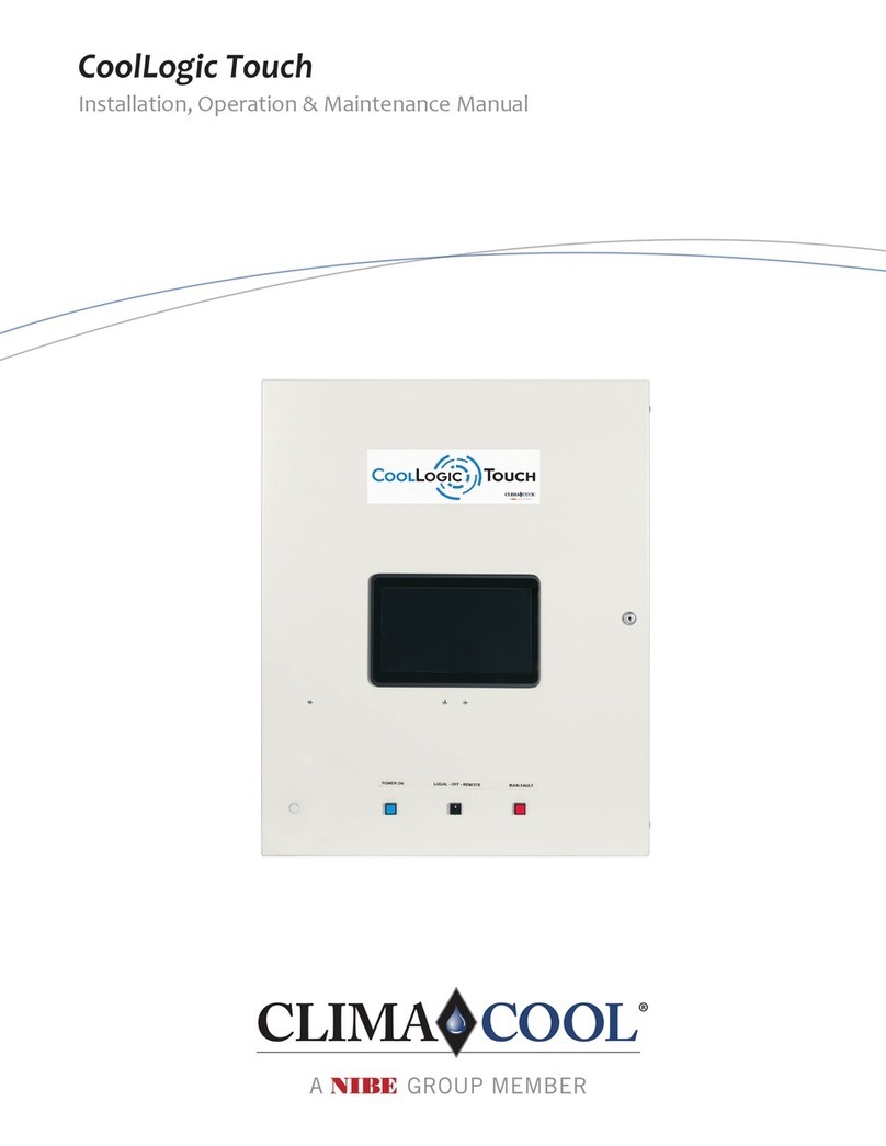
D+H CPS-M1-MSE-020 Series User manual

CPS-M1-MSE
D+H Downloads
99.828.70 1.2/07/22
en Original instructions..............................................Page ............................................................2

2/36 CPS-M1-MSE English 99.828.70 1.2/07/22
Introduction
Your D+H service and sales partner
Safety in the building is not only provided by the product. Safety is cre-
ated above all by competence. All D+H service and sales partners are
certied and regularly trained SHEV specialist companies. They work
closely with D+H Mechatronic AG as the manufacturer to implement
comprehensive system solutions for SHEV and natural building venti-
lation. With holistic support and continuous quality assurance in every
phase of the project: from consulting, planning and project conguration
to installation, commissioning, maintenance and service. This means
that the highest national and international quality standards are reliably
fullled.
Installation and commissioning
The comprehensive network of D+H service and sales partners is avail-
able to you for proper installation and commissioning. Our partner sys-
tem guarantees that D+H products are installed exclusively by trained
and experienced technicians in compliance with the technical directives
and regulations. Personal transfer and instruction of the operators are
included.
Maintenance and repairs
Building operators are responsible for the functional reliability of safety
devices in their own buildings.
Regular and proper maintenance ensures that your system will always
be operational. As SHEV specialist companies, the D+H service and
sales partners are optimally qualied for the maintenance. Owners/
operators can demonstrate at any time that they have fullled their
obligation by means of a service contract.
Quality with a warranty
You receive extended warranty benets for all D+H SHEV systems that
were installed by a D+H service and sales partner and are regularly
maintained. Ask your local D+H service and sales partner about this.
Always in your neighbourhood
We are represented around the globe with our network of subsidiaries
and exclusive partners.
Looking for a local D+H partner?
Simply visit our website:
www.dh-partner.com
WARNING
Read all the safety information, instructions, images and technical data
provided with this product.
Failure to observe the following instructions can result in electric shock,
re and/or serious injury.
Keep all the safety information and instructions in a safe place for future
reference.
Safety information
230 V AC operating voltage!
Risk of injury from electric shock!
• Only an authorised, electrically skilled person is allowed to connect
the power
• Keep children away from the controller
• Only use in dry spaces
• Only intended for installation indoors
• Only use unaltered D+H original parts
Content................................................................................................... 2
Introduction............................................................................................. 2
Safety information................................................................................... 2
Intended use........................................................................................... 3
MSE functional principle......................................................................... 3
Important regulations.............................................................................. 3
Example of application ........................................................................... 3
Performance features............................................................................. 3
Pictogram explanation............................................................................ 3
Overview of components........................................................................ 4
Control module – CM-BT1-D4-P2 .......................................................... 5
Actuator module – AM-1-2-10-24-D6-D2................................................ 5
Digital I/O module - IOM-D1-1212.......................................................... 5
Supply module – PSM-1-24-40 .............................................................. 5
Trigger module – TMA-1-D4-D12 ........................................................... 5
Bistable relay module - BRM-1-COC-0006 ............................................ 5
Actuator module - AM-1-1-08-230-D4-D2............................................... 6
Power packs PS-S1-24-20 and PS-S1-24-40 ........................................ 6
Analog/Digital I/O-Module - ADM-AD1-1212-4....................................... 6
Technical data......................................................................................... 7
24 V emergency supply.......................................................................... 7
Declaration of conformity........................................................................ 7
Arrangement of the modules .................................................................. 8
Installation of the module sockets .......................................................... 8
Removal of the module sockets ............................................................. 8
General instructions for connection........................................................ 9
Wiring diagram (sample) ........................................................................ 9
Connection – PSM................................................................................ 10
Connection – Mains switching...............................................................11
Connection – CM.................................................................................. 12
Connection – Digital inputs and outputs............................................... 13
Further top hat rail levels for additional CPS-M modules ..................... 13
Battery for the clock of the event memory............................................ 13
Connection – soft starter ...................................................................... 14
Connection – BRM ............................................................................... 15
Connection – Frequency converter ...................................................... 16
Connection – IOM................................................................................. 17
Connection – Star-delta circuit ............................................................. 18
Connection – ADM................................................................................ 19
Connection – ADM................................................................................ 20
Connection – AM 24 ............................................................................. 21
Connection – Vent buttons to AM 24 .................................................... 21
Connection – AM 24 with ACB drives................................................... 22
Connection – AM 24 with ACB drives................................................... 22
Connection – AM 24 with pole-changing drives.................................... 22
Connection – AM 24 with pole-changing drives.................................... 22
Connection – Spring return motor ........................................................ 23
Connection – AM 230 ........................................................................... 24
Connection – NSV 401 control and vent button to AM 230 .................. 24
Connection – NSV 401 power supply and D+H ACB drives................. 25
Connection – NSV 401 power supply and D+H drives......................... 25
Connection – NSV 401 power supply and third-party drives................ 26
Connection – TMA................................................................................ 27
Connection – TMA (2 lines) .................................................................. 28
Connection – TMA parallel connection RT ........................................... 29
Connection – TMA to re alarm system (FAS) ..................................... 29
Description of the inputs and outputs ................................................... 30
Commissioning and conguration with the SCS software.................... 31
Standard congurations........................................................................ 31
Description of the software functions.................................................... 32
Operation - Touch panel (optional) ....................................................... 33
Operation - Daily ventilation ................................................................. 34
Operation - Weather automation .......................................................... 34
Operation - SHEV................................................................................. 34
Operation - Trigger on alarm ................................................................ 35
Operation - Closing after alarm ............................................................ 35
Warranty ............................................................................................... 36
Inspection ............................................................................................. 36
Disposal................................................................................................ 36
Maintenance and cleaning.................................................................... 36
Content

3/36CPS-M1-MSEEnglish
99.828.70 1.2/07/22
Intended use
• Modular MSE controller for complex control tasks
• Can be used in the AdComNet SHEV bus system
• Combine lines and groups however you want
• Convenience functions for daily ventilation
• Only intended for installation indoors
Example of application
Pictogram explanation
Control panel O.K.
Fault
SHEV alarm
MSE functional principle
The following functions run simultaneously in the event of smoke detection
and subsequent triggering of the MSE. 1:
1. supply and discharge After successful feedback, the smoke extraction
fans are switched on. 2.
2. the smoke is removed via temperature-resistant smoke extraction fans.
These fans can be installed either on the roof, in the wall of the respective
utilisation units or centrally. In the case of interior rooms, the smoke is led
out of the building via an appropriate duct system. In doing so, it must be
ensured that the smoke does not re-enter adjacent utilisation units. To
avoid this undesirable eect, appropriate re dampers can be installed
within the duct system. 3.
3. postow openings near the oor are opened so that supply air can ow
in at the required ow velocity within the low-smoke layer accordingly. If a
free afterow is not possible, fresh air is supplied mechanically. The smoke
layer must not be destroyed.
Practical tip: For the implementation of complex smoke extraction sce-
narios, a combination of mechanical and natural supply air tracking is
possible.
Important regulations
It is necessary to observe VDE 0833 for danger alarm systems, VdS
2221, VDE 0100 for electrical systems, DIN 18232 for SHEV systems,
the provisions of the local re brigade and of the energy supply compa-
ny for the mains connection.
EN 12101-10 Energy supply
EN 12101-7 Smoke extraction ducts
EN 12101-8 Smoke dampers
EN 12101-3 Fire gas fans
EN 12101-1 Smoke curtains
Performance features
General
Variable module technology for complex control requirements
Flexible system structure through mounting rail system for all modules
and extensions
Connection of supply and communication through integrated plug
connectors
Retrottable modules in case of building modications
Parameterisable MRA and ventilation functions via D+H Software SCS
Inputs and outputs monitored for line breakage and short circuit
Connection of max. 30 re detectors or 10 MRA control points per
monitored line input
AdComNet bus system for seamless networking of modules within the
CPS-M and other D+H AdComNet components
Flexible use of parameterisable, digital inputs and outputs
24 V DC
2x max. 10 A drive current per actuator module
Stabilised output voltage due to switching power supply technology
No signal loss in case of mains failure due to integrated emergency
power supply (72 hours)
230 V AC
Emergency power supply (72 hours)
Up to 45, 230 V AC drives can be connected per drive group (1840VA)
400 V AC
Fans can be controlled either via frequency converter, soft starter or
directly.
Power supply via main switch and with automatic mains switchover if
required.
OK
External control
CO, NO, LPG sensors
MSE operation panel
Smoke detector
Drives for intake
air opening
Fire damper
Smoke extraction
fan
Jetfan
CCS / BMS
Line
Group
CPS-M
CPS-M
KNX, Modbus gateway
AdComNet enable
D+H control panel
AdComNet
400V AC

4/36 CPS-M1-MSE English 99.828.70 1.2/07/22
Overview of components
Supply module socket
MS-S1-RD-TS
Basic module socket
MS-D1-RR-TS
Expansion module socket
MS-S1-DD-TS
Bus termination module
BTM-1-1
Is plugged into the last
module socket.
Bus connection
Connection for the
power supply
Temperature control sensor unit
TCSU1-RJ12
RJ12 connecting cable (2x)
CC-TP/TCSU-1000 (1 m)
CC-TP/TCSU-2000 (2 m)
Touch panel with bracket (optional)
TP-C1-35-RJ12
RJ12 socket
Control module
CM-BT1-D4-P2
Control module
CM-B-1-D4-P2
Mains supply module
PSM-1-24-040
24 V DC actuator module
AM-1-2-10-24-D6-D2
24 V DC actuator module
AM-B-1-2-10-24-D4-D2
230 V AC actuator module
AM-1-1-08-230-D4-D2
Analogue / Digital
I/O module
ADM-AD1-1212-4
Analogue trigger module
TMA-1-D4-D12
Digital I/O module
IOM-D1-1212
Bistable relay module
BRM-1-COC-0006

5/36CPS-M1-MSEEnglish
99.828.70 1.2/07/22
Control module – CM-BT1-D4-P2 Control module – CM-B-1-D4-P2
• Central control element of the control panel (segment coupler)
• One CM controller module is required for each CPS-M
• Each CM controller module can manage up to 29 addition-
al modules (PSM, AM, TMA)
• AdComNet interfaces for implementing decentralised sys-
tems in combination with other AdComNet control panels
• 1000 SCS links and 100 connectors possible
• USB interface for conguring the system and the con-
nected drives (only ACB), and for rmware updates of the
control panel
• Integrated LEDs to indicate operation (green), fault
(yellow), alarm (red) and AdComNet operation
• Status displays for all modules of the respective CPS-M
as well as emergency operation of the individual lines and
groups using the 3.5" TFT touch panel
• Three user-programmable digital inputs for connecting
buttons, switches, external controls etc.
• Two user-programmable, isolated change-over contacts,
for example, for fault and alarm notications
• Integrated event memory for system analysis and traceability
• Connection using removable spring-type terminals
• Conductor cross-sections max. 1.5 mm² exible
• Dimensions WxHxD: 26x130x125 mm
• Installation on a 35 mm top hat rail in combination with a
basic module socket
• Central control element of the control panel (segment coupler)
• One CM controller module is required for each CPS-M
• Each CM controller module can manage up to 29 addition-
al modules (PSM, AM, TMA)
• 30 SCS links and 10 connectors possible
• USB interface for conguring the system and the con-
nected drives (only ACB), and for rmware updates of the
control panel
• Integrated LEDs to indicate operation (green), fault
(yellow), alarm (red) and AdComNet operation
• Status displays for all modules of the respective CPS-M
as well as emergency operation of the individual lines and
groups using the 3.5" TFT touch panel
• Three user-programmable digital inputs for connecting
buttons, switches, external controls etc.
• Two user-programmable, isolated change-over contacts,
for example, for fault and alarm notications
• Integrated event memory for system analysis and traceability
• Connection using removable spring-type terminals
• Conductor cross-sections max. 1.5 mm² exible
• Dimensions WxHxD: 26x130x125 mm
• Installation on a 35 mm top hat rail in combination with a
basic module socket
Supply module – PSM-1-24-040
• Power supply of the control panel system
• Max. 40 A load current for each supply module
depending on the power supply unit
• If a load current of more than 40 A is required, another
PSM (including supply module socket) can be used.
• The PSM always provides power to the actuator and
trigger modules used to the right of it
• Automatic toggling between mains supply and battery
supply in case of a mains outage
• Max. battery capacity 26 Ah (battery type 6)
• 72 hours of emergency supply time
• Integrated protection against excessive discharge
• Temperature-controlled charging voltage with external
temperature sensor
• Integrated LED to indicate a fault (yellow)
• Two connections for peripherals that are and are not
supplied with emergency power
• Connection using removable spring-type terminals
• Conductor cross-sections max. 2.5 mm² exible or for
supply and battery 6 mm² exible
• Dimensions WxHxD: 26x130x125 mm
• Installation on a 35 mm top hat rail in combination with
a basic module socket or for more than one power
supply unit with a supply module socket
Actuator module – AM-1-2-10-24-D6-D2 Actuator module – AM-B-1-2-10-24-D4-D2
• Module for connecting 24 V DC actuators
• 2 independent groups for connecting drives, each with
a total maximum current of 10 A
• The cable is monitored for breaks and short circuits
via the terminal module EM-47K
• Each group is electronically protected against
overload
• 4 user-programmable digital inputs (e.g. ventilation
button)
• 2 user-programmable digital outputs (e.g. NOT
CLOSED signal)
• 2 integrated ACB interfaces for reading out and
conguring the connected ACB drives
• Can be used with 24 V DC pole-changing drives, ACB
drives, spring-return motors and magnets
• Virtual groups in connection with ACB drives possible
• Adjustable ventilation time and opening width for
everyday ventilation
• Integrated LEDs to indicate a fault (yellow) and alarm
(red)
• Connection using removable spring-type terminals
• Conductor cross-sections max. 2.5 mm² Flexible
• Dimensions WxHxD: 26x130x125 mm
• Installation on a 35 mm top hat rail in combination with
an expansion module socket
• Module for connecting 24 V DC actuators
• 2 independent groups for connecting drives, each with
a total maximum current of 10 A
• The cable is monitored for breaks and short circuits
via the terminal module EM-47K
• Each group is electronically protected against
overload
• 4 user-programmable digital inputs (e.g. ventilation
button)
• 2 user-programmable digital outputs (e.g. NOT
CLOSED signal)
• Can be used with 24 V DC pole-changing drives
• Integrated LEDs to indicate a fault (yellow) and alarm
(red)
• Connection using removable spring-type terminals
• Conductor cross-sections max. 2.5 mm² Flexible
• Dimensions WxHxD: 26x130x125 mm
• Installation on a 35 mm top hat rail in combination with
an expansion module socket
Trigger module – TMA-1-D4-D12
• Module for connecting trigger peripheral devices
• Two independent lines for connecting a max. of 10
SHEV buttons and 30 re detectors per line (only
detectors approved by D+H may be used)
• Cables are monitored by the EM-L01 terminal module
• The SCS software can be used to congure the lines
also as user-programmable digital inputs and outputs
• Integrated LEDs to indicate a fault (yellow) and alarm
(red)
• Connection using removable spring-type terminals
• Conductor cross-sections max. 1.5 mm² exible
• Dimensions WxHxD: 26x130x125 mm
• Installation on a 35 mm top hat rail in combination with
an expansion module socket

6/36 CPS-M1-MSE English 99.828.70 1.2/07/22
Power packs PS-S1-24-20 and PS-S1-24-40
Functions:
• Output: 24 V DC, 20 A or 40 A
• Installation on 35 mm top hat rail
• Low ripple
• Reverse-voltage protected and short-circuit resistant
• Multiple power supply units can be combined
• For each power supply unit, one PSM supply module is needed
Technical data:
Type PS-S1-24-20 PS-S1-24-40
Rated input voltage 230 V AC ± 15%
Frequency 45 to 65 Hz
Nominal power 530 VA / 480 W 1040 VA / 960 W
Output voltage 24 V DC ± 1%
Ripple < 50 mVSS
Output current 20 A 40 A
Short-circuit resistant YES
Can be connected in parallel YES
Reverse-voltage protected YES
Input line connection max. 6 mm² star / max. 4 mm² exible
Output line connection max. 6 mm² star / max. 4 mm² exible
max. 16 mm² star / max. 16 mm² exible
Dimensions WxHxD 90x130x150 mm 140x130x150 mm
Bistable relay module - BRM-1-COC-0006
• Six user-programmable, isolated change-over contacts,
for switching signals with 24 V DC or 230 V AC
• change-over contacts as bistable version
• Denition of a switch-o state in the event of a mains and
battery failure possible (failsafe function)
• Integrated LEDs to indicate a fault (yellow) and alarm
(red)
• Connection using removable spring-type terminals
• Conductor cross-sections max. 2.5 mm² exible
• Dimensions WxHxD: 26x130x125 mm
• Installation on a 35 mm top hat rail in combination with
an expansion module socket
Digital I/O module - IOM-D1-1212
• 12
user-programmable digital inputs
• 12
user-programmable digital outputs
• The digital inputs can also be parameterised as LT inputs
• Integrated LEDs to indicate a fault (yellow) and alarm
(red)
• Connection using removable spring-type terminals
• Conductor cross-sections max. 1.5 mm² exible
• Dimensions WxHxD: 26x130x125 mm
• Installation on a 35 mm top hat rail in combination with
an expansion module socket
Actuator module - AM-1-1-08-230-D4-D2
• Module for connecting 230 V AC actuators
• 1 group for connecting drives with a total maximum
current of 8 A
• Up to 45 drives per AM 230 connectable
• D+H 230 V AC drives with SHEV fast mode (HS) are
supported
• The cable is monitored for breaks and short circuits
via the terminal module EM 230
• 2 user-programmable digital inputs (e.g. ventilation
button)
• 1 user-programmable digital output (e.g. NOT
CLOSED signal)
• Can be used with 230 V AC standard drives
• Adjustable ventilation time and opening width for
everyday ventilation
• Integrated LEDs to indicate a fault (yellow) and alarm (red)
• Connection using removable spring-type terminals
• Conductor cross-sections max. 2.5 mm² exible
(230 V AC) or 1.5 mm² exible (24 V DC)
• Dimensions WxHxD: 26x130x125 mm
• Installation on a 35 mm top hat rail in combination with
an expansion module socket
AD I/O module - ADM-AD1-1212-4
• 4
user-programmable multifunctional inputs
(digital or
analog)
• 8
user-programmable digital inputs
• 12
user-programmable digital outputs
• 4 virtual adjustable threshold switches per analog input
from which a virtual user-congurable digital input is set
or reset
• The digital inputs can also be parameterised as LT inputs
• Integrated LEDs to indicate a fault (yellow) and alarm
(red)
• Connection using removable spring-type terminals
• Conductor cross-sections max. 1.5 mm² exible
• Dimensions WxHxD: 26x130x125 mm
• Installation on a 35 mm top hat rail in combination with
an expansion module socket

7/36CPS-M1-MSEEnglish
99.828.70 1.2/07/22
Type CPS-M1-MSE-020-xxxx CPS-M1-MSE-040-xxxx CPS-M1-MSE-060-xxxx CPS-M1-MSE-080-xxxx
Supply 230 V AC, ± 15%, 45 to 60 Hz
Performance*
Performance in standby*
530 VA / 480 W
ca. 7.5 W
1040 VA / 960 W
ca. 8.5 W
1570 VA / 1440 W
ca. 16 W
2080 VA / 1920 W
ca. 17 W
Output voltage
Ripple
24 V DC ± 1%
< 50 mVSS
Nominal output current 20 A 40 A 60 A 80 A
Mode of operation
- Monitoring
- Alarm state / ventilation
Continuous duty
Short-time duty (30 % duty cycle)
Housing Sheet steel
Colour RAL 7035, light grey
Type of protection IP 54 (VdS IP 30)
Protection class I
Temperature range -5 to +40 °C
Air humidity 5% to 95% RH
Installation acc. to ICE 61439 up to 2000 m/üMN
Dimensions W x H x D 500 × 500 × 210 mm 600 × 800 × 250 mm 600 × 800 × 250 mm 800 × 1000 × 300 mm
* For 230 V AC systems plus the power of the NSV 401 and the connected 230 V AC drives
Technical data
• Emergency supply time: 72 hours
• Only use VdS-approved batteries.
• The sum of the nominal currents of the drives and actuators that are
triggered when there is an alarm must not exceed the max. permitted
load of the respective battery type
• The required battery capacity has to be determined for each PSM.
• The sum of the required ampere-hours (Ah) of all components,
including a 30% reserve, must be smaller than the capacity of the
battery
Standard batteries:
For each PS-S1-24-20 (+PSM): 2 x battery type 5 (12 V, 18 Ah ± 15%)
For each PS-S1-24-40 (+PSM): 2 x battery type 6 (12 V, 26 Ah ± 15%)
A special battery calculator is available for the exact determination
of the required battery capacity.
24 V emergency supply
Components Approx. Ah required for 72 hours
Intrinsic consumption by CM 0.52 Ah
CM supply of the modules 0.018 Ah per module
PSM 0.29 Ah
IOM 0,26 Ah
BRM 0,21 Ah
TMA 0.58 Ah
AM 0.43 Ah
AM 230 0,3 Ah
Fire detector 0.005 Ah
Smoke vent button 0.014 Ah
24 V DC Drives / actuators for
180 sec.
0.18 Ah (for each 1 A nominal
current)
Alarm devices 250 mA for 180
sec.
0.045 Ah
Devices and digital outputs with
an emergency supply (can be
adjusted using SCS)
7.2 Ah (for each 100 mA output
current)
Digital outputs with an emer-
gency supply (can be adjusted
using SCS)
3.6 Ah (for each 50 mA output
current)
Touch panel 0.4 Ah
Required capacity = Sum of the required Ah plus a 30% reserve
Battery type Max. permitted
load through
drives / actuators
Connector
Battery type 4 (12 Ah ± 15%) 24 A Flat plug
6,35 mm
Battery type 5 (18 Ah ± 15%) 36 A hole cable
lug Ø 5 mm
Battery type 6 (26 Ah ± 15%) 52 A
Declaration of conformity
We declare under our sole responsibility that the product described
under "Technical Data" complies with the following directives:
2014/30/EU, 2014/35/EU, 2011/65/EU
S.I. 2016/1091, S.I. 2016/1011, S.I. 2012/3032
Technical documents stored at:
D+H Mechatronic AG, D-22949 Ammersbek
Dirk Dingfelder Maik Schmees
CEO CTO
06.07.2022
ACB interface
ACB is used for secure communication between the drive and com-
patible D+H control systems. It enables activation, diagnostics and
conguration with perfect position, directly from the control panel. In this
process, all status messages, such as the OPEN and CLOSED signals,
opening stroke and drive errors are transmitted to the control panel.
The ACB bus is based on an open Modbus RTU protocol via which the
actuator can be directly controlled and queried.
Further information can be found in the D+H ACB Planning Manual.
Max. Number of drives per ACB connection:
AM 24 = max. 20 ACB drives
AM 230 = max. 20 ACB drives (CDC-5-ACB = max. 15)
In conjunction with locking drives (VLD, FRA),
a maximum of 10 drives (incl. locking drives) can be
connected.
Topology of the ACB bus line:
• Stub lines max. 15m
• Total length incl. stubs max. 200m.
• To avoid interference, the cables from the drive to the AM module
must be laid close together.

8/36 CPS-M1-MSE
1
1
2
2
3
3
CM PSM AM AM TMA TMA PSM AM AM TMA TMA
2x Akku Type 6
PS-S1-24-40
2x Akku Type 6
PS-S1-24-40
English 99.828.70 1.2/07/22
Arrangement of the modules
• Each CM controller module can manage up
to 29 additional modules (PSM, AM, TMA)
• The rst PSM provides power to the CM
module as well as to the AM and TMA
modules to the right of it
• Each additional PSM always provides power
only to the modules to the right of it
• This applies also to the emergency battery
power. Therefore, the modules are to be
distributed evenly across the PSM modules
• Due to the higher current consumption and
shorter cable paths, the AM 24 modules
are each to be used rst next to the PSM
module
• The total current of the drives respectively
connected to the PSM must not exceed
the output current of the respective power
supply unit.
Installation of the module sockets
Removal of the module sockets

9/36CPS-M1-MSE
4x 0,8 Ø
6x 0,8 Ø (RT 45)
10x 0,8 Ø (RT 45-LT)
6x 0,8 Ø (RT 45)
10x 0,8 Ø (RT 45-LT)
2x 0,8 Ø
2x 0,8 Ø
OK
OK
4x 0,8 Ø
English99.828.70 1.2/07/22
General instructions for connection
• The connections, particularly the earth connections, may be connected to the respective associated PSM supply module and components only.
No cross-ow of current may occur.
• System voltage 24 V DC and/or 230 V AC!
• If 24 V DC and 230 V AC cables are laid in the same cable duct in the control panel,
it must be ensured that the insulation of each conductor must be designed for the highest nominal voltage (≤ 250 V).
• A green-yellow core may only be used as protective earth conductor.
Wiring diagram (sample)
When selecting and routing cables, regional
installation requirements pertaining to electric
cable systems and necessary safety devices,
and/or directives pertaining to maintaining the
function of electrical cables must be observed
(e.g. MLAR guidelines for the re protection
requirements to be met by cable systems in
Germany).
Note:
Due to the variety available on the market,
no type designations are specied for these
cables. Please contact your D+H Partner for
this information.
Cable line (control panel - detector)
The cables are monitored for short circuits and
line breaks.
Cables for D+H SHEV systems
Cable group (control panel - drive)
At least three-wire design:
• 2 wires for supplying the drive (Mot.a/
Mot.b)
• For pole-changing drives, 1 additional
wire for cable monitoring, through which
the SHEV high-speed (HS) signal is also
transmitted to the drive.
• For ACB drives, 2 additional wires for the
bus connection.
Cross-section (mm²) = cable length (m) x total current
80
Wind/rain sensor
SHEV control panel
External control
SHEV operation panel
Approx. 1.5 m
above upper edge
of nished oor
Ventilation button
Approx. 1.2 m
above upper edge
of nished oor
Fire detector
SD-O 371 or FD-T 271
Drive on
SHEV opening
See cable lengths and cross sections
230 V AC 50 Hz
Separate power circuit.
Identify the fuse.
to additional
Total current 1 A 2 A 3 A 4 A 5 A 6 A 7 A 8 A 9 A 10 A
2 x 1,5 mm² 120 60 40 30 24 20 17 15 13 12 m
2 x 2,5 mm² 200 100 65 50 40 33 28 25 22 20 m
• max. cable length 500 m
• min. cable cross section 1.5 mm²
• A maximum voltage drop of 6.5% (3% with
third-party drives) on the cables is permitted.
• Max. 45 drives can be connected to a group
• The following two formulas must always be
used to calculate cable cross sections. The
higher value must be used.
Cable lengths and cross sections for Mot.a and Mot.b (AM 24 / 24 V drives)
Cable lengths and cross sections for L ▲, L▼, N and PE (AM 230 / 230 V drives)
Total power consumption 200 VA 500 VA 800 VA 1100 VA 1400 VA 1700 VA 1840 VA
5 x 1,5 mm² 167 167 167 132 104 85 79 m
5 x 2,5 mm² 278 278 278 220 173 142 131 m
5 x 4 mm² 444 444 444 351 276 227 210 m
Formula 1: Cross section (mm²) = Basic cable length (m) x total power of all Drives (VA)
96600
Formula 2: Cross section (mm²) = Basic cable length (m)
111

10/36 CPS-M1-MSE
X2.1 X2.4
4321
PSM-1-24-040
1
1
2
2
SNT–
BATT–
SNT+
BATT+
RJ12
TCSU1
X2
X6 X5 X4
–
+
–
N+
–
+–
+
++–––
LN
Output: 24 V DC
PS-1-24-20/40
Input: 230 V AC, 50 Hz
TCSU1-RJ12
L
N
PE
X4
X5.2
X6.2
X5.1
X6.1
X6
X2
X5
X4
English 99.828.70 1.2/07/22
230 V AC, 50 Hz
Separate power circuit.
Identify the fuse.
Do not reverse L+N!
Connect PE
Connection – PSM
RJ12 connecting cable
CC-TP/TCSU
(max. 2 m)
BatteryBattery
No. Name Description
X2.1 N+ Output potential without an emergency supply for
ventilation functions, max. 500 mA
X2.2 - Reference potential (do not connect to P-)
X2.3 + Output potential with an emergency supply, max.
500 mA
X2.4 - Reference potential (do not connect to P-)
X4 TCSU1 RJ12 connection of external battery temperature
sensor
X5.1 BATT+ Secondary power supply (battery),
max 40 A
X5.2 BATT-
X6.1 SNT+ Primary power supply (power pack),
max 40 A
X6.2 SNT-

11/36CPS-M1-MSE
4321
4321
BRM-1-COC0006
4
4
4
3
3
3
2
2
2
1
1
1
X1 X2 X3
X6 X5 X4
COM 6
NO 6
NC 6
COM 6
COM 5
NO 5
NC 5
COM 5
COM 4
NO 4
NC 4
COM 4
4321
NO 3
COM 3
COM 3
NC 3
COM 2
NO 2
COM 1
COM 1
COM 2
NC 2
NO 1
NC 1
N
X1.1
L1
L2
L3
PE
N
L1
L2
L3 T3
T2
T1
L1
L2
L3 T3
T2
T1
Q1
PE
63A
T2
T3
X1.2
L1
L2
L3
PE
N
Q2.1
8
7
Q3.1
2
1
4
3
6
5
F1
L3L2L1
T1
8
7
2
1
4
3
6
5
F2 B13A
230V~24V=
L N PE
SNT+
SNT–
PS-S1-24-40
T1
4321
PSM-1-24-40
1
1
2
2
SNT–
BATT–
SNT+
BATT+
RJ12
TCSU1
X2
X6 X5 X4
–
+
–
N+
–
+–
+
TCSU1-RJ12
A
A
A1
A2
Q2.1
A1
A2
Q3.1
22
21
Q2.1
22
21
Q3.1
English99.828.70 1.2/07/22
Connection – Mains switching
Main switch
Phase monitoring relay
Power supply
400V~/25A/50Hz
Power supply
400V~/25A/50Hz
Emergency power supply
on site

12/36 CPS-M1-MSE
4
4
3
3
2
2
RJ12
1
1
CM-BT1-D4-P2
TP-C1
NO 1
NO 2
NC 1
NC 2
COM 2
n.c.
n.c.
5
1
1
4
2
2
3
3
3
2 1
DI 1.3
ACN D+
ACN D+
DI 1.2
ACN D-
ACN D-
DI 1.4
–
n.c.
Shield
Shield
X1 X2 X3
X6 X5 X4
COM 1
TP-C1-35-RJ12
X1.1 X1.4
X2.1 X2.4
X3
X4.3
X5.3
X6.5 X6.1
X4.1
X5.1
X1
X6
X2
X5
X4
X3
English 99.828.70 1.2/07/22
No. Name Description
X1.1 n.c. n.c.
X1.2 NO 1 Isolated change-over contact, max. 35 V / 1 A,
collective alarm (factory setting, can be pro-
grammed using SCS)
X1.3 COM 1
X1.3 NC 1
X2.1 n.c. n.c.
X2.2 NO 2 Isolated change-over contact, max. 35 V / 1 A,
general malfunction (factory setting, can be pro-
grammed using SCS)
X2.3 COM 2
X2.4 NC 2
X3 TP-C1 RJ12 connection for touch panel
X4.1 Shield AdComNet master interface
X4.2 ACN D-
X4.3 ACN D+
X5.1 Shield AdComNet slave interface
X5.2 ACN D-
X5.3 ACN D+
X6.5 n.c. n.c.
X6.4 DI 1.2 Freely congurable digital input,
0 to 28 V, active minus or plus,
control panel OPEN (factory setting, can be pro-
grammed using SCS)
X6.3 DI 1.3 Freely congurable digital input,
0 to 28 V, active minus or plus,
control panel CLOSED (factory setting, can be
programmed using SCS)
X6.2 DI 1.4 Freely congurable digital input,
0 to 28 V, active minus or plus
X6.1 - Reference potential (do not connect to P-)
Connection – CM
* Termination:
Every segment must be
terminated with 2 resistors
(110 Ω).
The resistors must be
connected as far apart as
possible.
Connections that are not used
also have to be terminated!
Isolated change-over contacts, max. 35 V / 1 A,
(factory settings, can be programmed using SCS)
Collective alarm General malfunction
Freely congurable
digital inputs
Central OPEN
Central CLOSE
Earth the
shielding
once per segment.
RJ12 connecting cable
CC-TP/TCSU
Relay de-en-
ergizes on
fault
Relay
energizes
on alarm

13/36CPS-M1-MSE
CM / AM / TMA / IOM
DI x.1
–
–
DO x.1
24 V DC
CM PSM AM AM TMA TMA
CM PSM AM AM TMA TMA
CM PSM AM
X4.3
X5.3 X5.3
X4.1
X5.1 X5.1
ACN D+
ACN D-
Shield
ACN D+
ACN D-
Shield
English99.828.70 1.2/07/22
Connection – Digital inputs and outputs
Contact Inverted Signal
Open O 0
Closed O 1
Open On 1
Closed On 0
active minus
˄
either
˅
active plus
Digital inputs
Digital outputs
24 V DC
Each max. 50 mA
(programmable using SCS)
Battery for the clock of the event memory
The CM module has a built-in lithium battery on the underside, which
buers the internal clock of the event memory in the event of a power
failure.
The battery should be replaced at least every 10 years.
Attention! Folgende Reihenfolge beachten:
1. Read out and save existing parameterization
2. Change battery. Battery type: Lithium cell CR1216
3. Read in parameterization again
* Termination:
The AdComNet segment must
be terminated with 2 resistors
(110 Ω).
The resistors must in each case
be connected at the end of the
cable.
Connections that are not used
also have to be terminated! Earth the segment
shielding once.
Further top hat rail levels for additional CPS-M modules
If a top-hat rail is not sucient for the conguration of your system, a further top-hat rails can be integrated in the following way.
Further top-hat rail rows are assembled like the rst row of the CPS-M (see « Arrangement of the modules » page 8 )
Connect the AdComNet master interface X4 on the CM module of the rst row to the AdComNet slave interface X5 on the CM module of the
additional row. If you need additional module rows, proceed in the same way.
You can connect to any CM via USB and use the connected rows as a common control panel.
LT inputs, lines and groups can be freely linked across all rows.

14/36 CPS-M1-MSE
5432
1
5432
1
IOM-D1-1212
5
5
5
4
4
4
3
3
3
2 1
2 1
2 1
X1 X2 X3
X6 X5 X4
5432
1
–
DO 1.1
DO 1.2
DO 1.4
DO 1.3
–
DO 2.4
DO 2.4
DO 2.1
DO 2.3
DO 3.2
–
DO 3.1
DO 3.4
DO 3.3
–
DI 3.2
DI 3.3
DI 3.4
DI 3.1
–
DI 2.2
DI 2.3
DI 2.4
DI 2.1
–
DI 1.2
DI 1.3
DI 1.4
DI 1.1
T1
N
PE
T2
T3
T1
N
PE
T2
T3
2 6
5
4
3
2
1
Q2.1
X2
1
2
3
PE
M
3~
U
V
W
PE
1T1 1T2 1T3
1L3 1L2 1L1
13
14
21
22
HIS HIS HIO HIO PE
C13A
F1
1
L1 3
L2 5
L3
T1
2
T2
4
T3
6
Q2.2
3
L2
1
L1
5
L3
42 6
T2T1 T3
Q2.3
4321
4321
BRM-1-COC0006
4
4
4
3
3
3
2
2
2
1
1
1
X1 X2 X3
X6 X5 X4
COM 6
NO 6
NC 6
COM 6
COM 5
NO 5
NC 5
COM 5
COM 4
NO 4
NC 4
COM 4
4321
NO 3
COM 3
COM 3
NC 3
COM 2
NO 2
COM 1
COM 1
COM 2
NC 2
NO 1
NC 1
A1
A2
Q2.1
+A1
-A2
+U 13
S
Q2.3
13
14
F1
95
98
X2
95
96
Q2.2
English 99.828.70 1.2/07/22
Connection – soft starter
Soft starter
Revision switch
Revision switch

15/36CPS-M1-MSE
X1.1 X1.4
X2.1 X2.4
X3.1 X3.4
BRM
X4.4 X4.1
X5.4 X5.1
X6.4 X6.1
BRM
4321
4321
BRM-1-COC-0006
4
4
4
3
3
3
2
2
2
1
1
1
X1 X2 X3
X6 X5 X4
COM 6
NO 6
NC 6
COM 6
COM 5
NO 5
NC 5
COM 5
COM 4
NO 4
NC 4
COM 4
4321
NO 3
COM 3
COM 3
NC 3
COM 2
NO 2
COM 1
COM 1
COM 2
NC 2
NO 1
NC 1
4321
COM x
COM x
NO x
NC x
BRM
X1
X6
X2
X5
X4
X3
English
99.828.70 1.2/07/22
Connection – BRM
Nr. Name Beschreibung
X1.1 NC 1 Floating output 1 - normally closed *
X1.2 COM 1 Floating output 1 – COM
X1.3 NO 1 Floating output 1 – normally open *
X1.4 COM 1 Floating output 1 – COM
X2.1 NC 2 Floating output 2 – normally closed *
X2.2 COM 2 Floating output 2 – COM
X2.3 NO 2 Floating output 2 – normally open *
X2.4 COM 2 Floating output 2 – COM
X3.1 NC 3 Floating output 3 – normally closed *
X3.2 COM 3 Floating output 3 – COM
X3.3 NO 3 Floating output 3 – normally open *
X3.4 COM 3 Floating output 3 – COM
X4.4 COM 4 Floating output 4 – COM
X4.3 NO 4 Floating output 4 – normally open *
X4.2 COM 4 Floating output 4 – COM
X4.1 NC 4 Floating output 4 – normally closed *
X5.4 COM 5 Floating output 5 – COM
X5.3 NO 5 Floating output 5 – normally open *
X5.2 COM 5 Floating output 5 – COM
X5.1 NC 5 Floating output 5 – normally closed *
X6.4 COM 6 Floating output 6 – COM
X6.3 NO 6 Floating output 6 – normally open *
X6.2 COM 6 Floating output 6 – COM
X6.1 NC 6 Floating output 6 – normally closed *
* 5 ... 30 V DC, 10 mA ... 3 A / 5 ... 265 V AC, 10 mA ... 3 A, cos φ = 1
The "Failsafe power failure" parameter can be used to dene the state
of the potential-free contact to be taken in the event of a failure of the
mains and battery supply. If the "None" conguration is selected, the
last status is retained.

16/36 CPS-M1-MSE
X2
1
2
3
PE
3~
U
V
W
PE
L1
L2/N
L3
U V W PE
T2
C16A
F1
T1
N
PE
T2
T3
T1
N
PE
T2
T3
1T1 1T2 1T3
1L3 1L2 1L1
13
14
21
22
HIS HIS HIO HIO PE
4321
4321
BRM-1-COC0006
4
4
4
3
3
3
2
2
2
1
1
1
X1 X2 X3
X6 X5 X4
COM 6
NO 6
NC 6
COM 6
COM 5
NO 5
NC 5
COM 5
COM 4
NO 4
NC 4
COM 4
4321
NO 3
COM 3
COM 3
NC 3
COM 2
NO 2
COM 1
COM 1
COM 2
NC 2
NO 1
NC 1
T1
English 99.828.70 1.2/07/22
Connection – Frequency converter
Revision switch
Frequency converter
Lüftergeschwindigkeit 1
Lüftergeschwindigkeit 2
FWD
+24 V

17/36CPS-M1-MSE
X1.1 X1.5
X2.1 X2.5
X3.1 X3.5
IOM
X4.5 X4.1
X5.5 X5.1
X6.5 X6.1
IOM
5432
1
5432
1
IOM-D1-1212
5
5
5
4
4
4
3
3
3
2 1
2 1
2 1
X1 X2 X3
X6 X5 X4
5432
1
–
DO 1.1
DO 1.2
DO 1.4
DO 1.3
–
DO 2.4
DO 2.4
DO 2.1
DO 2.3
DO 3.2
–
DO 3.1
DO 3.4
DO 3.3
–
DI 3.2
DI 3.3
DI 3.4
DI 3.1
–
DI 2.2
DI 2.3
DI 2.4
DI 2.1
–
DI 1.2
DI 1.3
DI 1.4
DI 1.1
IOM
DI x.x
–
24 V DC
DO x.x
–
X1
X6
X2
X5
X4
X3
English
99.828.70 1.2/07/22
Connection – IOM
Nr. Name Beschreibung
X1.1 DO 1.4 freely congurable digital output
1.4 *
X1.2 DO 1.3 freely congurable digital output
1.3 *
X1.3 - Reference potential (do not connect to P-)
X1.4 DO 1.2 freely congurable digital output
1.2 *
X1.5 DO 1.1 freely congurable digital output
1.1 *
X2.1 DO 2.4 freely congurable digital output
2.4 *
X2.2 DO 2.3 freely congurable digital output
2.3 *
X2.3 - Reference potential (do not connect to P-)
X2.4 DO 2.2 freely congurable digital output
2.2 *
X2.5 DO 2.1 freely congurable digital output
2.1 *
X3.1 DO 3.4 freely congurable digital output
3.4 *
X3.2 DO 3.3 freely congurable digital output
3.3 *
X3.3 - Reference potential (do not connect to P-)
X3.4 DO 3.2 freely congurable digital output
3.2 *
X3.5 DO 3.1 freely congurable digital output
3.1 *
X4.5 DI 1.1 freely congurable digital input
1.1 **
X4.4 DI 1.2 freely congurable digital input
1.2 **
X4.3 - Reference potential (do not connect to P-)
X4.2 DI 1.3 freely congurable digital input
1.3 **
X4.1 DI 1.4 freely congurable digital input
1.4 **
X5.5 DI 2.1 freely congurable digital input
2.1 **
X5.4 DI 2.2 freely congurable digital input 2.2 **
X5.3 - Reference potential (do not connect to P-)
X5.2 DI 2.3 freely congurable digital input
2.3 **
X5.1 DI 2.4 freely congurable digital input
2.4 **
X6.5 DI 3.1 freely congurable digital input
3.1 **
X6.4 DI 3.2 freely congurable digital input
3.2 **
X6.3 - Reference potential (do not connect to P-)
X6.2 DI 3.3 freely congurable digital input
3.3 **
X6.1 DI 3.4 freely congurable digital input
3.4 **
*
max. 50 mA, short-circuit-proof
**
0 ... 28 V,
active minus or plus
(not galvanically isolated)
< either >
active plus
active minus
Digital inputs
Digital outputs
24 V DC
Each max. 50 mA
(programmable using SCS)

18/36 CPS-M1-MSE
1O 2O 3O
1I 2I 3I
13
14
21
22
HIS HIS HIO HIO PE
4O 5O 6O
4I 5I 6I
S1
3~ W2U1
U2V1
V2W1
PE
3
1
2
6
4
5
T1
N
PE
X2 X2
135
246
135 135
246 246
Q2 Q3 Q4
C16A
F1
1
L1 3
L2 5
L3
T1
2T2
4T3
6
Q5
T1
N
PE
T2
T3
T2
T3
5432
1
5432
1
IOM-D1-1212
5
5
5
4
4
4
3
3
3
2 1
2 1
2 1
X1 X2 X3
X6 X5 X4
5432
1
–
DO 1.1
DO 1.2
DO 1.4
DO 1.3
–
DO 2.4
DO 2.4
DO 2.1
DO 2.3
DO 3.2
–
DO 3.1
DO 3.4
DO 3.3
–
DI 3.2
DI 3.3
DI 3.4
DI 3.1
–
DI 2.2
DI 2.3
DI 2.4
DI 2.1
–
DI 1.2
DI 1.3
DI 1.4
DI 1.1
F1
95
98
95
96
Q5
4321
4321
BRM-1-COC0006
4
4
4
3
3
3
2
2
2
1
1
1
X1 X2 X3
X6 X5 X4
COM 6
NO 6
NC 6
COM 6
COM 5
NO 5
NC 5
COM 5
COM 4
NO 4
NC 4
COM 4
4321
NO 3
COM 3
COM 3
NC 3
COM 2
NO 2
COM 1
COM 1
COM 2
NC 2
NO 1
NC 1
+
-stern
dreieck
Q4 Q3
Q2 Q3 Q4
English 99.828.70 1.2/07/22
Connection – Star-delta circuit
Revision switch

19/36CPS-M1-MSE
X1
X6
X2
X5
X4
X3
English99.828.70 1.2/07/22
Nr. Name Beschreibung
X1.1 DO 1.4 freely congurable digital output
1.4
max. 50 mA, short-circuit-proof
X1.2 DO 1.3 freely congurable digital output
1.3
max. 50 mA, short-circuit-proof
X1.3 - Reference potential (do not connect to P-)
X1.4 DO 1.2 freely congurable digital output
1.2
max. 50 mA, short-circuit-proof
X1.5 DO 1.1 freely congurable digital output
1.1
max. 50 mA, short-circuit-proof
X2.1 DO 2.4 freely congurable digital output
2.4
max. 50 mA, short-circuit-proof
X2.2 DO 2.3 freely congurable digital output
2.3
max. 50 mA, short-circuit-proof
X2.3 - Reference potential (do not connect to P-)
X2.4 DO 2.2 freely congurable digital output
2.2
max. 50 mA, short-circuit-proof
X2.5 DO 2.1 freely congurable digital output
2.1
max. 50 mA, short-circuit-proof
X3.1 DO 3.4 freely congurable digital output
3.4
max. 50 mA, short-circuit-proof
X3.2 DO 3.3 freely congurable digital output
3.3
max. 50 mA, short-circuit-proof
X3.3 - Reference potential (do not connect to P-)
X3.4 DO 3.2 freely congurable digital output
3.2
max. 50 mA, short-circuit-proof
X3.5 DO 3.1 freely congurable digital output
3.1
max. 50 mA, short-circuit-proof
X4.5 DI/AI 1.1 freely congurable multifunctional input
1.1 *
digital
0 ... 28 V,
active minus or plus
analog 0 ... 10 V
X4.4 DI/AI 1.2 freely congurable multifunctional input
1.2 *
digital
0 ... 28 V,
active minus or plus
analog 0 ... 10 V
X4.3 - Reference potential (do not connect to P-)
X4.2 DI/AI 1.3 freely congurable multifunctional input
1.3 *
digital
0 ... 28 V,
active minus or plus
analog 0 ... 10 V
X4.1 DI/AI 1.4 freely congurable multifunctional input
1.4 *
digital
0 ... 28 V,
active minus or plus
analog 0 ... 10 V
X5.5 DI 2.1 freely congurable digital input
2.1 *
digital
0 ... 28 V,
active minus or plus
X5.4 DI 2.2 freely congurable digital input 2.2 *
digital
0 ... 28 V,
active minus or plus
X5.3 - Reference potential (do not connect to P-)
X5.2 DI 2.3 freely congurable digital input
2.3 *
digital
0 ... 28 V,
active minus or plus
X5.1 DI 2.4 freely congurable digital input
2.4 *
digital
0 ... 28 V,
active minus or plus
X6.5 DI 3.1 freely congurable digital input
3.1 *
digital
0 ... 28 V,
active minus or plus
X6.4 DI 3.2 freely congurable digital input
3.2 *
digital
0 ... 28 V,
active minus or plus
X6.3 - Reference potential (do not connect to P-)
X6.2 DI 3.3 freely congurable digital input
3.3 *
digital
0 ... 28 V,
active minus or plus
X6.1 DI 3.4 freely congurable digital input
3.4 *
digital
0 ... 28 V,
active minus or plus
* not galvanically isolated
Connection – ADM

20/36 CPS-M1-MSE
X1.1 X1.5
X2.1 X2.5
X3.1 X3.5
ADM
X4.5 X4.1
X5.5 X5.1
X6.5 X6.1
ADM
5432
1
5432
1
ADM-A1-1212-4
5
5
5
4
4
4
3
3
3
2 1
2 1
2 1
X1 X2 X3
X6 X5 X4
5432
1
–
DO 1.1
DO 1.2
DO 1.4
DO 1.3
–
DO 2.4
DO 2.4
DO 2.1
DO 2.3
DO 3.2
–
DO 3.1
DO 3.4
DO 3.3
–
DI 3.2
DI 3.3
DI 3.4
DI 3.1
–
DI 2.2
DI 2.3
DI 2.4
DI 2.1
–
DI/AI 1.2
DI/AI 1.3
DI/AI 1.4
DI/AI 1.1
ADM
DO x.x
–
X1 / X2 / X3
ADM
DI x.x
–
24 V DC
X6 / X5
ADM
DI/AI x.x
–
24 V DC
X4
ADM
DI/AI x.x
–
0 ... 10 V DC
X4
24 V DC
N+ –
in out
English 99.828.70 1.2/07/22
Connection – ADM
< either >
< either >
active plus
Separate signal conditioner *
active plus
active minus
active minus
Digital inputs
Multifunctional inputs
(programmable using SCS)
Digital:
Analog:
Digital outputs 24 V DC each max. 50 mA
(programmable using SCS)
* Without a separate signal conditioner there is no galvanic isolation.
Sensors supplied by the CPS-M do not require an signal conditioner.
This manual suits for next models
4
Table of contents
Other D+H Control System manuals
Popular Control System manuals by other brands

Nice
Nice WIDES User, installation and safety instructions
Precision Engineering
Precision Engineering Bimba PCS user manual

Roberts Gorden
Roberts Gorden CORAYVAC installation manual
Lennox
Lennox Harmony III Homeowner's manual

Yetter
Yetter AIR ADJUST 2940 Operator's manual
Siemens
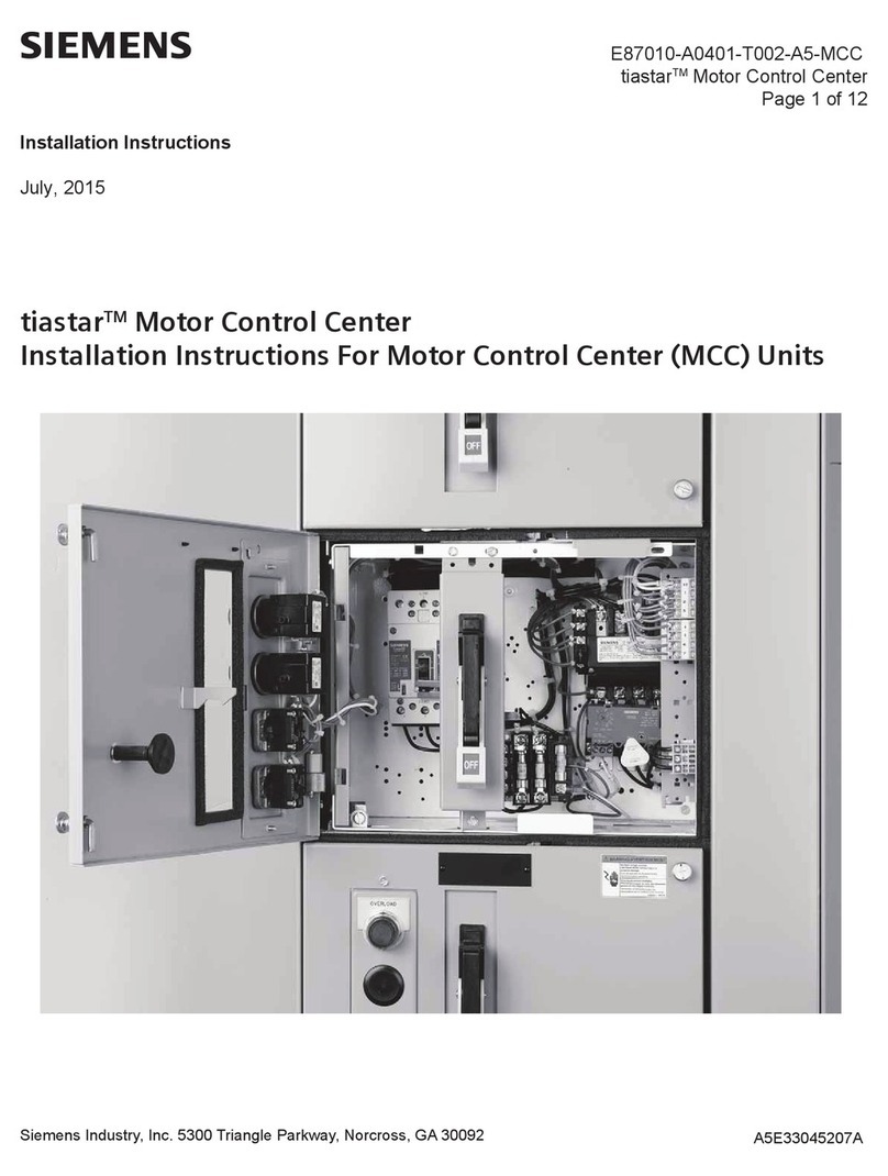
Siemens tiastar MCC installation instructions
