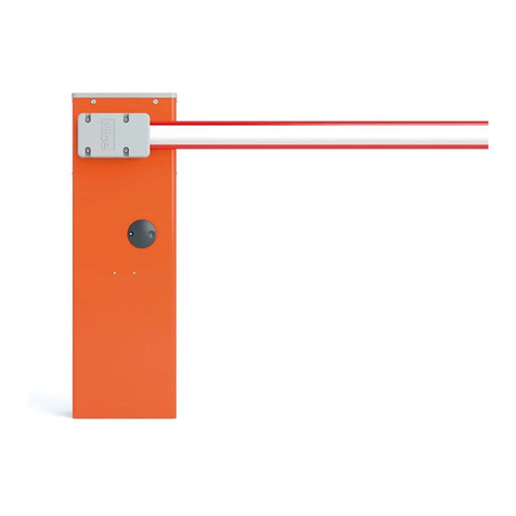
Nice WIDES Operating instructions

EN - User, installation and safety instructions
Electromechanical road barrier
WIDES - WIDESI
WIDEM - WIDEMI
WIDEL - WIDELI
WIDES/ V1 - WIDESI/ V1
WIDEM/ V1 - WIDEMI/ V1
WIDEL / V1 - WIDELI/ V1
Nice

CE declaration of conformity
and declaration of incorporation of partly-completed machinery
Declaration in accordance with the following Directives:
2014/30/UE (EMC); 2006/42/CE (MD) annex II, part B
Note: The contents of this declaration correspond to declarations in the ofcial document led in the ofces of Nice S.p.A. and, in par-
ticular, the latest version thereof available prior to the printing of this manual. The text herein has been re-edited for editorial purposes. A
copy of the original declaration can be requested from Nice S.p.A. (TV) Italy.
Declaration number: 561/WIDE Revision: 2 Language: EN
Manufacturer's Name: NICE S.p.A.
Address: Via Pezza Alta 13, 31046 Rustignè di Oderzo (TV) Italy
Person authorised to compile the technical documentation: NICE S.p.A.
Type of product: Electro-mechanical barrier
Model / Type: WIDES, WIDESI, WIDEM, WIDEMI, WIDEL, WIDELI
Accessories: -
The undersigned, Roberto Griffa, as Chief Executive Ofcer, hereby declares under his own responsibility that the product identied above
comply with the provisions of the following directives:
• DIRECTIVE 2014/30/EU OF THE EUROPEAN PARLIAMENT AND OF THE COUNCIL of 26 February 2014 on the harmonisation of the
laws of the Member States relating to electromagnetic compatibility (recast), in accordance with the following harmonised standards:
EN 61000-6-2:2005, EN 61000-6-3:2007+A1:2011
• DIRECTIVE 2014/35/EU OF THE EUROPEAN PARLIAMENT AND OF THE COUNCIL of 26 February 2014 on the harmonisation of the
laws of the Member States relating to electromagnetic compatibility (recast), in accordance with the following harmonised standards:
EN 60335-1:2002 + A1:2004 + A11:2004 + A12:2006 + A2:2006 + A13:2008 + A14:2010 + A15:2011
EN 60335-2-103:2003 +A11:2009
In addition, the product conforms to the following directive in accordance with the provisions applicable to partly completed machinery:
• Directive 2006/42/EC OF THE EUROPEAN PARLIAMENT AND COUNCIL of 17 May 2006 regarding machines and amending directive
95/16/EC (consolidated text)
- It is hereby declared that the relevant technical documentation has been compiled in accordance with Annex VII Part B of Directive
2006/42/CE and that the following essential requirements have been applied and fullled: 1.1.1- 1.1.2- 1.1.3- 1.2.1-1.2.6- 1.5.1-1.5.2-
1.5.5- 1.5.6- 1.5.7- 1.5.8- 1.5.10- 1.5.11
- The manufacturer undertakes to transmit, in response to a reasoned request by the national authorities, relevant information on the
partly completed machinery. This shall be without prejudice to the intellectual property rights of the manufacturer of the partly completed
machinery.
- Should the partly completed machinery be put into service in a European country with an ofcial language different to the one used in
this declaration, a translation into that language must be provided by the person bringing the machinery into the language area in question.
- The partly completed machinery may not be put into service until the nal machinery into which it is to be incorporated has been declared
in conformity with the provisions of Directive 2006/42/EC, where appropriate.
All parts of the product subject to the following standards comply with them:
EN 13241-1:2003+A1:2011, EN 12445:2002, EN 12453:2002, EN 12978:2003+A1:2009
Oderzo, 14 June 2016 Ing. Roberto Griffa
(Chief Executive Ofcer)

English – 1
CONTENTS
CE DECLARATION OF CONFORMITY
GENERAL WARNINGS:
SAFETY - INSTALLATION - USE 2
A - Special warnings in relation to European directives
applicable to the product 2
B - Installation criteria and special warnings in connection
with essential requirements 3
1 - PRODUCT DESCRIPTION AND INTENDED USE 4
2 - OPERATING LIMITS
2.1 - Product durability 5
3 - INSTALLATION 6
4 - ELECTRICAL CONNECTIONS
4.1 - Types of electrical cables 17
4.2 - Electrical cable connections 17
5 - STARTING THE AUTOMATION AND CHECKING THE
CONNECTIONS
5.1 - Hooking the automation up to the mains 19
6 - TESTING AND COMMISSIONING
6.1 - Testing 21
6.2 - Commissioning 22
7 - PROGRAMMING
7.1 - Control unit 23
7.2 - Programmable functions 23
8 - FURTHER DETAILS
8.1 - Connecting a radio receiver 25
8.2 - Power for external devices 25
8.3 - Connecting boom lights 26
8.4 - Connecting photocells within the barrier mechanism
(box) 26
8.5 - Connecting the back-up battery 27
9 - PRODUCT DISPOSAL 28
10 - BASIC TROUBLESHOOTING... 28
11 - TECHNICAL SPECIFICATIONS 29
MAINTENANCE SCHEDULE (detachable insert) 31
User manual (end user version) 33
(detachable insert)

English – 2
GENERAL WARNINGS: SAFETY - INSTALLATION - USE (original instructions in Italian)
CAUTION Important safety instructions. Follow all instructions as improper installation may cause serious damage
CAUTION Important safety instructions. It is important for you to comply with these instructions for your own and other
people's safety. Keep these instructions
•Before commencing the installation, check the “Product technical specications”, in particular whether this product is suitable for automating
your guided part. If it is not suitable, DO NOT continue with the installation.
•The product cannot be used before it has been commissioned as specied in the chapter on “Testing and commissioning”
CAUTION According to the most recent European legislation, the implementation of an automation system must comply
with the harmonised standards provided by the Machinery Directive in force, which enables declaration of the
presumed conformity of the automation. Taking this into account, all operations regarding connection to the
electricity grid, as well as product testing, commissioning and maintenance, must be performed exclusively by
a qualied and skilled technician!
•Before proceeding with the installation of the product, check that all materials are in good working order and suited to the intended
applications
•The product is not intended for use by persons (including children) with reduced physical, sensory or mental capacities, nor by anyone with
insufcient experience or familiarity.
•Children must not play with the appliance
•Do not allow children to play with the xed control devices of the product. Keep the remote controls out of reach of children.
CAUTION In order to avoid any danger from inadvertent resetting of the thermal cut-off device, this appliance must not be powered
through an external switching device, such as a timer, or connected to a supply that is regularly powered or switched off by
the circuit
•Provide a disconnection device (not supplied) in the plant’s mains power supply, with a contact opening distance that permits complete
disconnection under the conditions dictated by overvoltage category III
•Handle the product with care during installation, taking care to avoid crushing, denting or dropping it, or allowing contact with liquids of any
kind. Keep the product away from sources of heat and naked ames. Failure to observe the above can damage the product, and increase
the risk of danger or malfunction. If this should happen, stop installation immediately and contact Customer Service.
•The manufacturer assumes no liability for damage to property, items or persons resulting from non-compliance with the assembly instructions.
In such cases the warranty for material defects is excluded
•The weighted sound pressure level of the emission A is lower than 70 dB(A)
•Cleaning and maintenance to be carried out by the user must not be carried out by unsupervised children
•Before working on the system (maintenance, cleaning), always disconnect the product from the mains power supply
•Check the system periodically, in particular all cables, springs and supports to detect possible imbalances, signs of wear or damage. Do not
use, if repairs or adjustments are necessary, since installation failure or an incorrectly balanced automation may cause injury
•The packing materials of the product must be disposed of in compliance with local regulations
•When operating a biased-off switch, make sure that other persons are kept away from the automation.
•When performing an operation, keep an eye on the automated mechanism and keep all bystanders at a safe distance until the movement
has been completed
•Do not operate the automation if anyone is working on it; disconnect its power supply before permitting such work to be done
•If the power cable is damaged, it must be replaced by the manufacturer or the latter's technical assistance service, or by a similarly qualied
person, in order to prevent any type of risk
INSTALLATION PRECAUTIONS
•Prior to installing the drive motor, check that all mechanical components are in good working order and properly balanced, and that the
automation moves correctly
•Make sure that the controls are at a safe distance from the moving parts, while allowing a good view of them.
Unless a switch is used, the controls should be installed at least 1.5m off the ground and should not be accessible
•If the opening movement is controlled by a re system, make sure that any windows larger than 200mm are closed by the controls
•Make sure that nothing can be trapped between the moving and xed parts during manoeuvres
•Permanently afx the manual operation label next to the manual control
• After installing the drive motor, make sure that the mechanism, protective system and all manual manoeuvres operate properly

English – 3
A - Special warnings in relation to European directives applicable to the product
• “Construction Products” Directive:
Special warnings for this product in relation to the Construction Products Regulation No. 305/2011:
- The full installation of this product, as described in this instruction manual and for certain types of use (e.g. excluding use solely for vehicles),
may cause the product to fall within the scope of Regulation No. 305/2011 and its harmonised standard EN 13241-1.
- In paragraph B “Installation criteria and special warnings in relation to essential requirements”, all necessary installation criteria are given to
ensure that the product meets the essential requirements of Regulation No. 305/2011; the installer must verify and ensure that all these criteria
have been scrupulously complied with.
- The essential requirements might not be guaranteed if the road barrier mechanism is installed and used without compliance with one or more
of these criteria. It is forbidden to use the product in these situations until the installer has verified the compliance with the Direc-
tive requirements; in this case the label attached to the product must be removed immediately and the “EC Declaration of Conformity” (An-
nex I to this manual) cannot be used. As a result, the installer in turn becomes the manufacturer of the “automatic barrier” product and must
comply with the provisions of Regulation No. 305/2011 and its harmonised standard EN 13241-1. In this case the road barrier mechanism
must be considered as “partly-completed machinery” and the “Declaration of Conformity” of Annex II can be used (for inclusion in the techni-
cal documentation).
• “Machinery” Directive:
- In paragraph B “Installation criteria and special warnings in relation to essential requirements”, all necessary installation criteria are given to
ensure that the product meets the essential requirements of the Machinery Directive. The installer must verify and ensure that all these criteria
have been scrupulously complied with.
- The essential requirements might not be guaranteed if the road barrier mechanism is installed and used without compliance with one or
more of these criteria. It is forbidden to use the product in these situations until the installer has verified the compliance with the
Directive requirements; in this case the “EC Declaration of Conformity: Annex I” cannot be used. As a result, the installer in turn becomes
the manufacturer of the “automatic barrier” product and must comply with the provisions of the Machinery Directive. The manufacturer must
make an assessment of the associated risks, including a list of the essential safety requirements as envisaged in “Appendix I of the Machinery
Directive”, specifying the related adopted solutions. Note that the risk assessment is one of the documents included in the automation Techni-
cal documentation. This must be completed by a professional installer, and the “Declaration of conformity” of Annex II can be used and must
be filled in by the installer of the road barrier mechanism.
Special warnings regarding the use of this product in relation to the “Machinery” Directive; these are to be taken into considera-
tion if the installer becomes the manufacturer of the product.
• The road barrier mechanism comes onto the market as “partly-completed machinery” and is therefore manufactured to be integrated into a
machine or assembled with other machines in order to create “a machine” pursuant to Machinery Directive, only in combination with other com-
ponents and in the manner described in this instruction manual. As specified in the Machinery Directive, the use of this product is not admitted
until the manufacturer of the machine on which this product is mounted has identified and declared it as conforming to the Machinery Directive.
• “Low Voltage” Directive:
Special warnings regarding the fitness of use of this product in relation to the “Low Voltage” Directive.
This product meets the provisions in the “Low Voltage” Directive if used for the use and in the configurations specified in this instruction manual
and in combination with the items in the Nice S.p.A. product catalogue.
If the product is used in unspecified configurations or with other unspecified products, the requirements may not be guaranteed; the use of the
product in these situations is prohibited until the installer has verified compliance with the specified requirements of the directive.
• “Electromagnetic compatibility” Directive:
Special warnings regarding the fitness of use of this product in relation to the “Electromagnetic compatibility” Directive.
This product has been subjected to electromagnetic compatibility tests in the most critical situations of use and in the configurations specified
in this instruction manual and in combination with the items in the Nice S.p.A. product catalogue.
If the product is used in unspecified configurations or with other unspecified products, the electromagnetic compatibility may not be guaran-
teed; the use of the product is prohibited in these situations until the installer has verified compliance with the specified requirements of the di-
rective.
B - Installation criteria and special warnings in connection with essential requirements
When installed correctly, this product meets the essential requirements laid down in Regulation No. 305-2011 according to the requirements in
harmonised standard EN 13241-1, as indicated in Table A and in the European directive on “Machinery”.
Caution! – If the road barrier mechanism were intended solely for the transit of vehicles, it would be excluded from the scope of EN 13241-1; in
this case, compliance with some of the requirements in Table A may not be required. Transit may be considered “solely for vehicles” when other
types of transit (e.g. for pedestrians) are expressly prohibited – for example with appropriate signs – and when adequate space is provided in the
immediate vicinity if other types of transit are required.
TABLE A - Essential requirements for CE marking (according to table ZA.1 of EN 13241-1)
Essential characteristics Clauses in the standard Result
Water-tightness 4.4.2 PND*
Releasing of hazardous substances 4.2.9 Compliant
Resistance to wind load 4.4.3 Compliant
Thermal resistance 4.4.5 PND*
Air permeability 4.4.6 PND*
Safe opening for vertically moving doors 4.2.8 Compliant
Definition of geometry of glass components 4.2.5 PND*
Mechanical resistance and stability 4.2.3 Compliant
Operating forces for power-operated closures 4.3.3 Compliant
Durability of water-tightness, thermal resistance and air permeability 4.4.7 PND*
* PND = Performance not declared, when the product does not offer this performance, e.g. “Air permeability”, or when the requirement is not
applicable, e.g. “Definition of geometry of glass components”.
• Releasing of hazardous substances:

English – 4
The product does not contain and/or release hazardous substances in accordance with the requirements of EN 13241-1 and according to the
list of substances on the website of the European Community
Special warning to ensure the continued compliance with the requirement – It is essential that the other materials used in the installa-
tion, such as electrical cables, comply with this requirement
• Resistance to wind load
Table B shows the resistance of the boom to the differential pressure of the wind. The tests were performed on the barrier equipped with an im-
pact protection profile; other accessories could increase its exposed surface area and thereby reduce its resistance to wind loads.
TABLE B
Type: WIDE S WIDE M WIDE L
Class
with XBA19
with XBA15
with XBA14 + XBA15
4
-
-
4
-
-
-
3
-
-
-
2
Wind pressure [Pa] > 1000 > 1000 > 700 > 450
Maximum wind speed [km/h] 151 151 126 101
Description Hurricane Hurricane Violent storm/gale Storm
• Safe opening for vertically moving doors
The product does not cause uncontrolled movements or allow the boom to drop in the event of failure of a single component of the suspension
or balancing (springs) system.
Special warnings to ensure continued compliance of the requirements:
- Install the product carefully following all the instructions described in Section 3 - Installation and Section 6 - Testing and commissioning.
- Make sure there is an organised maintenance schedule that follows scrupulously the provisions in the “Maintenance Schedule” Section (re-
movable insert at the end of the manual).
• Mechanical resistance and stability
The product is designed and manufactured so that the forces, impacts and stress incurred during normal use do not cause any damage or
jeopardise its mechanical performance.
Warning: See notes to the requirement “Safe opening for vertically moving doors”.
• Operating forces for power-operated closures
The operating forces exerted by the boom with regard to the risks of crushing and impact are safeguarded against by means of one of these
three methods:
1For operation with “hold-to-run command” (man present): as specified in EN 12453. In this case the command button must be placed
in view of the automation and if it is accessible to the public, the command button must not be available to them, e.g. use only with a key
switch.
2For “Semi-automatic” operation: by limiting the forces as specified in EN 12453
3For “automatic” operation: by limiting the forces as specified in EN 12453; in this case, at least one pair of photocells must necessarily be
installed as shown in Fig. 2.
Special warning to ensure continued compliance with the requirement: see notes to the requirement “Safe opening for vertically mov-
ing doors”.
1PRODUCT DESCRIPTION AND INTENDED USE
WIDE is an electromechanical road barrier mechanism for residential, public and industrial use: it controls the opening and closing of a driveway
with a width from 3 to 7 metres depending on the model chosen (S - M - L).
CAUTION! – All uses other than the intended use described and use in environmental conditions other than those described in
this manual should be considered improper and forbidden!
WIDE operates with electric power and, in the event of a power failure, you can use it manually by running the manual release. It can also be
used with a back-up battery (mod. PS324 - optional accessory) which ensures performance of certain operations during power failures.
model:
INSTALLABLE ACCESSORIES
Boom Rubber Lights Pivoting
attachment
Jointed
boom Aluminium skirt Mobile
support
WIDE S
3 m R XBA13 R XBA4 R WIA10 –R 1pc - WA13 –
4 m
XBA19 R XBA13 R XBA4 R WIA10 – – –
WIDE M 4 m
XBA19 R XBA13 R XBA4 R WIA10 R WIA11 R 2pcs - WA13 R WA12
WIDE L
3 + 3 m
XBA15 + XBA9 + XBA15 R XBA13 R XBA6 – – R 2pcs - WA13 R WA12
3 + 4 m
XBA15 + XBA9 + XBA14 R XBA13 R XBA18 – – – –
5 m
XBA5 R XBA13 R XBA6 – – R 2pcs - WA13 R WA12

English – 5
2APPLICATION LIMITS
Check that all the values shown in Section 12 - Product technical specifications and estimated durability (paragraph 2.1) are compatible with
the intended use.
2.1 - Product durability
Durability is the average economic life span of the product; its value is strongly influenced by the index of severity of the manoeuvres. To estimate
durability, proceed as described below:
01. Add up the values for the items in Table 1
based on the chosen barrier mechanism
model:
TABLE 1 SEVERITY INDEX
WIDE S WIDE M WIDE L
Jointed boom / 15% /
Presence of dust and sand 10% 10% 10%
Presence of Salinity 10% 10% 10%
Aluminium skirt 5% 5% 5%
Mobile support / 15% 15%
Ambient temperature above 40°C or below 0°C 5% 5% 5%
Operation interrupted by photocell 10% 15% 15%
Operation interrupted by Stop 10% 15% 15%
Speed setting (trimmer FL) above 50% 10% 10% 15%
Force setting (trimmer I) above 50% 5% 10% 10%
02. Depending on the chosen barrier mech-
anism model, proceed as follows on the
graph:
a - using the value found above, draw a
vertical line until it crosses the curve
b - from this point draw a horizontal line
until it crosses the line of “manoeuvre cy-
cles”
The obtained value is the estimated life
span of your product
0
100.000
200.000
300.000
cicli di manovre
400.000
500.000
10 20 30 40 50
Indice di gravosità (%)
60 70 80 90 100
Severity index (%)
manoeuvre cycles
List of available accessories:
XBA19 - aluminium boom painted white L4000 mm
XBA5 - aluminium boom painted white L5150 mm
XBA14 - aluminium boom painted white L4150 mm
XBA15 - aluminium boom painted white L3150 mm
XBA4 - Boom lights WIDE S / WIDE M
XBA6 - Boom lights WIDE L
XBA18 - Boom lights WIDE L
XBA9 - Universal joint
SIA1 - Foundation plate WIDE S / WIDE M
SIA2 - Foundation plate WIDE L
WA12 - Mobile support
WA13 - Aluminium skirt
WIA10 - Pivoting attachment
WIA11 - Jointed boom
PS324 - Emergency batteries
WA10 - Stickers
XBA13 - Rubber impact protection kit

English – 6
3INSTALLATION
Important! Before installing the product, refer to the 'WARNINGS' Section (at the beginning of the manual) and Section 12
(Technical specications).
Fig. 1 shows the contents of the package (based on the purchased model): check that everything is present and correct.
a - WIDE barrier mechanism cabinet (S-M-L)
b - photocell box for barrier mechanism cabinet
c - box for small hardware
d - anchors
e - manual lock/release key
f - Boom cap + 2 caps to cover the rubber impact protectors (these are
found in the box for small hardware)
g - boom support
h - foundation plate
i - boom connectors (only WIDE L)
WIDE S
WIDE M
WIDE L
1
a
b
e
e
e
f
f
f
i
g
g
g
h
h
h
c
d
Fig. 2 shows the location of the components of a typical installation using Nice accessories:
a - WIDE barrier mechanism (S-M-L) + boom
b - photocells
c - posts for photocells
d - key-operated selector switch
e - ashing light

English – 7
ad
e
c
c
c
b
b
2
Before proceeding with installation, check the installation dimensions (Fig. 3):
338 mm
205
mm
420
mm
1030 mm
314 mm
320
mm
205
mm
1000 mm
280
mm
286 mm
178
mm
1000 mm
3WIDE S WIDE M WIDE L
To install the barrier, proceed as described below:
01. Establish the installation position of the
various system components (e.g. Fig. 2):
- If the base does not exist, start from step
02
- If the base exists, start from step 06
02 06
02. Dig the foundation ditch and prepare the
tubes for the electrical cables: see Table 3
for the type of cables (Section 4)

English – 8
03. Secure the 4 anchors to the foundation
plate with one nut above and one below
The lower nut must be screwed up
to the end of the thread
04. Cast the concrete to secure the founda-
tion plate
Before the concrete hardens, make
sure the foundation plate is perfectly
level
05. Wait until the concrete hardens (usually at
least two weeks) and then remove the 4
upper nuts of the anchors
06. Fixing the barrier mechanism cabinet
a/b - unscrew the screws and remove the
cover
c/d - remove the cabinet door
a
bcd
e/f - position the cabinet and trace the xing points of the slots
g- drill these points on the support surface
h- insert 4 expansion anchors (not supplied)
i - set the cabinet and block it in position with the nuts and washers (not supplied)
ef
g
i

English – 9
07. Set the DIRECTION OF THE BOOM:
If you require LEFT-ORIENTED BOOM with the cabinet on the right (the factory setting), move to step 08 for the adjustment of
the balancing spring (N.B. in the factory it is anchored in non denitive holes)
WIDE S WIDE M WIDE L
7 m.
A
Only with 7 m boom place the balancing springs as shown in Figure “A”
If you require RIGHT-ORIENTED BOOM with the cabinet on the left, you must proceed as follows:
7 m.
A
WIDE S WIDE M WIDE L
rotate through 180° the motor connector (MOTOR - Fig. 5) and the connector of the limit switches (LIMIT SWITCH - Fig. 5)
180°
180°

English – 10
08. Adjusting the balancing spring, based on the model purchased:
In the factory, the balancing spring is anchored in non-denitive holes.
Move the balancing spring attachment into one of the holes on the other arm of the WIDE balance lever (based on the model purchased)
WIDE S
ab
cd
ef
l
90°
gh
i
WIDE S

English – 11
WIDE M
WIDE M
ab
cd
ef
l
90°
i
h
g

English – 12
7 m.
7 m.
WIDE L
WIDE L
ab
cd
ef
l
90°
gh
i
A
A
Only with 7 m boom place the balancing springs as shown in Figure “A”

English – 13
08. Installation of the boom and accessories:
a - insert the two pins in their correct positions (on the motor shaft)
b - position the support on the drive shaft into a “vertical boom” position and secure it with the specic screws and open grover wash-
ers, screwing with force
c - place the cover of the boom and secure it partially with the 6 screws
a
b
c
09. Assembly BOOM CONSISTING OF 1 PIECE (whole or cut):
ONLY for WIDE L, start the assembly from this point:
a- insert them into the free end of the boom (if necessary use a rubber mallet) and continue with step '10'
a
Assembly BOOM CONSISTING OF 2 PIECES (whole or cut):
CAUTION - With booms consisting of two pieces, you must secure the shorter piece of the boom to the aluminium
support.
ONLY for WIDE L, start the assembly from this point:
a - insert the universal joint into the free ends of the two booms. Important: pay attention to the orientation of the joint, because the
screw heads must be on the same side as the holes on the booms
b - unscrew the 3 screws in equal measure to expand the joint inside the booms and continue with step '10'
b
a

English – 14
10. a - lightly oil the aluminium rail on both sides
b - insert the rst piece of the rubber impact protector in the slot as far as the end of the boom: perform this action on both sides
a
b
c - insert the joint for the rubber impact
protector and repeat for the other pieces
Note - The rubber impact protector can
protrude about 1 cm from the end of the
aluminium prole
1 cm
c
d - put on the boom cap and secure it with
the 2 screws supplied
e - position and t together the two caps
to cover the rubber impact protectors
de
f - insert the whole boom within the sup-
port shell up to the stop, then fully tighten
the 6 screws on the support
f

English – 15
11. If any accessories are intended for the boom, they must be installed at this point: refer to the respective instruction manuals and Section
8 (Further details) in this manual
12. Adjust the mechanical stops of the limit
switches
WIDE S WIDE M WIDE L
13. Adjust the balancing of the boom, according to the model purchased:
IMPORTANT - Versions WIDE L:
WIDE L with 5 m boom = requires 1 balancing spring positioned/anchored so as to guarantee the balancing at 45°
WIDE L with 6/7 m boom = requires 2 balancing springs positioned/anchored so as to have the balancing at 45°
a - manually release the gearmotor
b - manually move the boom to about
half way (45°): if the boom remains still,
it means the balance is correct (a slight
imbalance is allowed).
WARNING - The boom must never
move heavily.
45°
20°
60°
45°
WIDE S
WIDE MWIDE L
WIDE S
WIDE MWIDE L
WIDE S
WIDE MWIDE L
WIDE S
WIDE MWIDE L
ab
If the boom does not remain still
proceed as follows:
1 = if the boom tends to rise
2 = if the boom tends to drop
ab
WIDE S
WIDE M
WIDE L
ab
45°
1

English – 16
45°
WIDE S ab
WIDE M ab
WIDE L
2
14. Lock the gearmotor
(based on the purchased model)
WIDE S
WIDE MWIDE L
WIDE S
WIDE MWIDE L
WIDE S
WIDE MWIDE L
WIDE S
WIDE
M
WIDE
L
15. If any other devices (accessories) are intended for the system, they must be installed at this point: refer to the respective instruction
manuals and Section 8 (Further details) in this manual
4ELECTRICAL CONNECTIONS
CAUTION! - All electrical connections must be made with the system powered off Incorrect connections can result in damage
and injury.
Fig. 4 shows the hookup of a typical installation; g. 5 shows the connections to be made on the control unit.
4.1 - Types of electrical cables: Fig. 4
Table 3 - Types of electrical cable (see g. 4)
Connection Type of cable Maximum length
APOWER 3 x 1.5 mm230 m *
B
C
FLASHER WITH AERIAL 1 cable: 2 x 1.5 mm2
1 shielded RG58 cable
10 m
10 m (< 5 m recommended)
DPHOTOCELLS 1 cable: 2 x 0.25 mm2(TX)
1 cable: 4 x 0.25 mm2(RX)
30 m
30 m
E - F KEY SWITCH 2 cables: 2 x 0.5 mm2 ** 20 m
* A power supply cable longer than 30 m may be used provided it has a larger gauge, e.g. 3x2.5mm2, and that a safety grounding system is
provided near the automation unit.
** The two 2 x 0.5 mm2cables can be replaced by a single 4 x 0.5 mm2cable.

English – 17
C
E
F
D
D
D
D
B
A
4
4.2 - Electrical cable connections: Fig. 5
Table 4 - Description of the electrical connections (see Fig. 5)
Terminals Function Description
3-4 Flashing light Output for ashing light connection; when a manoeuvre is in progress, the ashing cycle is 0.5 s ON and
0.5 s OFF
5-6 Services 24 VDC output ( -30% + 50%) to power the services, maximum 200 mA
7-8 Courtesy light It comes on at the start of the operation and goes off 60 seconds after it nishes
7-9 S.C.A. It is OFF when the boom is closed and ON when a manoeuvre is stopped with the boom in any position; it
ashes slowly during opening and rapidly during closing
7-10 Stop Input of normally closed (NC) type for devices which control blocking actions or the immediate stoppage
of the manoeuvre in progress
7-11 Photo Input of normally closed (NC) type for safety devices that cause reverse movement or stoppage if they
intervene during a closing manoeuvre
7-12 Photo 2 Input of normally closed (NC) type for safety devices that cause reverse movement or stoppage if they
intervene during an opening manoeuvre
7-13 Step-by-step Input of normally open (NO) type for command devices whose intervention results in opening or closing
with the sequence Open - Stop - Close - Stop
7-14 Open Input of normally open (NO) type for command devices whose intervention results in an opening manoeuvre
with the sequence: Open - Stop - Open - Stop
7-15 Close Input of normally open (NO) type for command devices whose intervention results in a closing manoeuvre
with the sequence Close - Stop - Close - Stop
43-44 Aerial Radio receiver aerial input The aerial can be incorporated into the ashing light or mounted externally.
Note 1: as an alternative to terminal 7 (common for all inputs and outputs) you can use terminal 6
Note 2:
• If the contact inputs of type NC (Normally Closed) are not used, they must be jumpered to terminal 6 or 7.
• Contact inputs of type NO (Normally Open) must be left empty, if they are not used.
• The contacts of the devices connected to the control unit must be of the mechanical type and free from any potential; no connections are
allowed to devices whose contacts are dened as “open collector”, “PNP” or “NPN” types.
Other
connections
on the control
unit
- Power supply transformer Connection to the secondary winding of the transformer
- Motor output for connection to motor
- Limit switch input for connections to opening and closing limit switches
- Radio (for accessories) connection for radio receivers with SM connector (OXI, etc.)
- Battery (for accessories) connection for PS324 battery

English – 18
TX
NC NO CC NO NC
1 2
RX FLASH
T1
T2
21 543
TX
1 2
RX
21 543
LED FCC
LED OK
LED
MOTOR
FLASH
PHOTO PHOTO PHOTO2 PHOTO2
+
0 V
+ 24 V
+ 24 V
PROGRAM SWITCH
LIMIT
SWITCH
TRIMMER TP FL FRI
FUSE
24 V
CLOSE
OPEN
P. P.
PHOTO2
PHOTO
ALT
LED FCA
12345678910
15
14
13
12
111098765
4
3
24 V
PS324
SM
5
AERIAL = AERIAL LED PHOTO = PHOTOCELL
LEDS
PROGRAM
SWITCH =MICRO
SWITCHES LED FCC = CLOSING LIMIT
SWITCH LED
TRIMMER = ADJUSTMENT
TRIMMER LED FCA = OPENING LIMIT
SWITCH LED
LED OK = OK LED LIMIT SWITCH = LIMIT SWITCH
LED OPEN = OPEN LED FLASH = FLASHING LIGHT
LED CLOSED = CLOSED LED FUSE = FUSE
LED P.P. = STEP-BY-STEP LED MOTOR = MOTOR
LED PHOTO2 = PHOTOCELL LEDS
To make the electrical hookup, proceed as described below with reference to Fig. 5:
01. a - unhook the control unit box from its
position
b - open the box a
g
b
f
02. c - drill through the sections prepared for
passing the cables
d - pull the cables of the intended de-
vices or of those already present in the
system through the hole (leaving an addi-
tional 20/30 cm of cable): for connecting
to the terminals see Fig. 5
c
d
This manual suits for next models
11
Table of contents
Other Nice Control System manuals
Popular Control System manuals by other brands

elsner elektronik
elsner elektronik WS1000 Style Assembly instructions

CorroVenta
CorroVenta SUPERVISION 2.0 user manual

Chromalox
Chromalox MicroTherm Installation & operation manual

Chamberlain
Chamberlain GAROG TST-2 Operational description

Trio
Trio UNIPLAY HMI quick start guide

ROTOTILT
ROTOTILT ICS Direct Translation of the original instruction