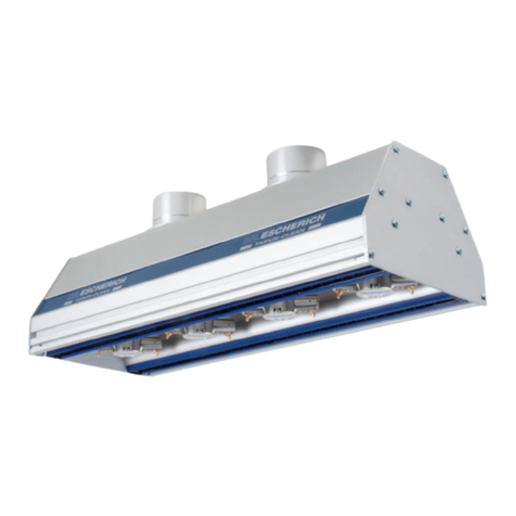
Dr. Escherich TAIFUN-CLEAN 012 User manual

Operating Instructions for:
TAIFUN-CLEAN 012/04/05/014/015
TAIFUN-CLEAN COMPACT
110/140/180/240 (AF)
Dr. Escherich GmbH
Höglwörther Straße 1
81369 München
phone: +49 (0)89 31 85 55-0
fax: +49 (0)89 31 85 55-66
www.dr-escherich.com
Subject to technical changes

1. Description of Product 3
1.1 Application 3
1.2 Function Principle 3
2. Safety Instructions 5
3. General Safety Instructions 6
4. Installation 7
4.1 Mechanical Installation 7
4.2 Compressed Air Connection 9
4.3 Compressed Air Rotating Nozzles Type TAIFUN-CLEAN 12
4.4 Suction Connection 12
4.5 Electrical Cables and High Voltage Supply 12
5. Start-Up 13
6. Errors 14
6.1 Error Display 14
6.2 Trouble Shooting Ionization System 14
6.3 Trouble Shooting Suction System 14
6.4 Returning the System 14
7. Maintenance 15
7.1 Regular Servicing 15
7.2 Replacing Compressed Air Rotating Nozzles Typ TC 16
7.3 Replacing the Ionization Systems 17
8. Technical Data Daten 2
9. Spare Parts and Accessories 19
9.1 Spare Parts 19
9.2 Accessories 20
10. Drawing and Ordering Codes 21
10.1 TAIFUN-CLEAN 04 21
10.2 TAIFUN-CLEAN 05 21
10.3 TAIFUN-CLEAN 012 22
10.4 TAIFUN-CLEAN 014 22
10.5 TAIFUN-CLEAN 015 23
10.6 TAIFUN-CLEAN Compact 110 23
10.7 TAIFUN-CLEAN Compact 180 24
10.8 TAIFUN-CLEAN Compact 180 AF 24
10.9 TAIFUN-CLEAN Compact Special Version 25
10.10 TAIFUN-CLEAN Rotating Nozzles 26
Product Overview 30
Contents

3
Operating Instructions for TAIFUN CLEAN
www.dr
-
escherich.com
Version 12/09
1.1 Application
TAIFUN-CLEAN is installed either above, below or adjacent to the material
surface to be cleaned. It neutralises electrostatic charges and removes
troublesome contamination by means of compressed air (and suction - in the
case of TAIFUN-CLEAN 012, 014 and 015). The device is not suitable for use in
potentially explosive atmospheres (EX environments). Models suitable for this
are available.
The ambient temperature must not exceed + 50°C.
The device must not come into contact with dampness, wetness or aggressive
media.
1.2 Function Principle
The ionization system (Fig. 1) generates positive and negative ions. Due to the
pulsating airstream from the rotating nozzles in combination with the ionization,
contaminating particles are released from the surface. In the case of TAIFUN-
CLEAN 012 014, 015 the particles are transported to the suction channel and
suctioned off in a targeted manner.
1. Description of Product

4
Operating Instructions for TAIFUN CLEAN
www.dr
-
escherich.com
Version 12/09
Fig 1: Function Principle
Position Description
1. Ionization system
2. Rotating nozzles
3. Suction (only for TC 014,015, 012,…)
4. Item to be cleaned
Tab. 1
1
2
3
4
1

5
Operating Instructions for TAIFUN CLEAN
www.dr
-
escherich.com
Version 12/09
2. Safety Instructions
If visible damage and possible electrical faults are identified, switch off
device immediately!
Danger! Danger of injury due to material transport near the device! Safety
equipment, e.g. guard plates and ON/OFF switch for immediate shut-down of
the system should be provided by the operator! Activate all safety equipment
and ON/OFF switch before start-up! Approach the device only when entire
system is switched off! Before initial start of the entire system, check that all
tools and foreign objects have been removed!
Life-threatening high voltage! Faulty cables and faulty high-voltage plugs can
cause injury due to electric power! Install conductive components only when de-
energised! Incorrect installation can cause damage to the cables! Plug in and
out coaxial connectors of ionizers only when de-energised! Observe the
operating instructions of the connected appliances!
Danger! Faulty compressed air lines and connectors can cause severe injury!
Install compressed air lines and connectors only when depressurised!
Note! Persons with heart pacemakers should keep a safety distance of 50 cm
from the high-voltage transformers
This symbol indicates danger for life and limb of persons and danger exists for
machine, material or the environment.
This symbol indicates danger for life and limb of the persons and danger exists
for machine, material or the environment due to dangerous voltage.

6
Operating Instructions for TAIFUN CLEAN
www.dr
-
escherich.com
Version 12/09
Safety in operational practice can only be assured when all required measures
for this are adopted. It is the duty of the machine operator to plan these
measures and check their implementation. In case of incorrect operation or
misuse, life and limb of the operator, the device and other material assets are
endangered.
In particular the operator must ensure that the device is used only according to
regulations and that the device is operated only in a faultless, fully-functional
state.
It must be assured that only sufficiently qualified and authorised personnel
operate, service and repair the device, that these persons are regularly
instructed on all corresponding matters of work safety and environmental
protection, that they know the operating instructions and the warnings contained
in them and that all safety and warning notices on the machine have not been
removed and remain readable.
These operating instructions must be kept at the machine. It must be assured
that than all persons who need to work at the machine can refer to the operating
instructions at all times. There are separate operating instructions for ionization
rods and supply units.
3. General Safety Instructions

7
Operating Instructions for TAIFUN CLEAN
www.dr
-
escherich.com
Version 12/09
The device must be inspected for damage in transit before beginning
installation.
Only persons who are correspondingly qualified and who observe the safety
instructions may perform the setup, assembly and installation of the device.
Install only when de-energised!
Connect only suitable supply units. In case unsuitable appliances are
connected, there is a risk of damage and destruction of the appliances. The
guarantee becomes invalid.
4.1 Mechanical Installation
The TAIFUN-CLEAN can be installed via the T-slot (TC 04, 05 and 015) or the
perforated plates (TC 012, TC 014, TAIFUN-CLEAN Compact, TAIFUN-CLEAN
Spot) at machines and manufacturing devices (s. Fig 2; s. Chapter 10 drawings;
screw diameter and max. permitted torque of the attach screws s. Table 1). The
screws should be re-tightened after two weeks.
For TAIFUN-CLEAN 012, the air guide plate LLB included in the delivery
package must be almost touching nearby machine components at the side to
ensure optimal output ventilation. If necessary the customer should place an
additional separating plate at the side.
The working clearance W (Fig. 2) of the device from the material surface can be
referred to in Table 1.
4. Installation

8
Operating Instructions for TAIFUN CLEAN
www.dr
-
escherich.com
Version 12/09
Model Mechanical
Installation
Maximal
Torque
Working Clearance
(min –max)
Optimal
Working
Clearance
TC 04 Slot fixture M8 in T-
slot 15 Nm* 20-150 mm 50 mm
TC 05 Nuts M8 in T-slot 15 Nm* 20-40 mm 30 mm
TC 014 Borehole
Ø 9 mm 55 Nm* 20-50 mm 50 mm
TC 015 Slot fixtures M8 in
T-slot 15 Nm* 20-30 mm 20 mm
TC
Spot 70
Boreholes
installation plate 55 Nm* 20-40 mm 30 mm
TC Spot 80 Borehole
Ø 9 mm 55 Nm* 20-40 mm 30 mm
TC 012 Borehole
Ø 9 mm 55 Nm* 20-40 mm 30 mm
TC Spot/Compact 110 Borehole
Ø 9 mm 55 Nm* 20-40 mm 30 mm
TC Compact
140/180/240 individual 55 Nm* 20-150 mm 50 mm
TC Compact
140/180/240 UL individual 55 Nm* 20-150 mm 50 mm
*The torque must not exceed the max. permitted torque of the screw
Tab. 2

9
Operating Instructions for TAIFUN CLEAN
www.dr
-
escherich.com
Version 12/09
Bild 2: Transportrichtung T und Arbeitsabstand W
Fig. 2: Transport direction T and work clearance W
For lightweight materials, suitable measures must be taken for retaining the
min. clearance between the material surface and the device, e.g. spacers,
material guides, guide rollers for stabilising the material.
No earthed machine components may be located in the immediate vicinity of
the ionization rods.
No additional components may be positioned between the ionizer and the
product surface (exception: electrically neutral slide elements if necessary)
4.2 Compressed Air Connection
The compressed air supply is connected to the compressed air line of the
TAIFUN-CLEAN device via a filter regulating valve with water/oil separator. The
compressed air must conform to quality class 3 (ISO 8537).
Constrictions to the diameter such as kinks, radii less than 3 x the hose
diameter and quick-fit connectors in the air line must be avoided. Compressed
air lines must be kept as short as possible. The operating pressure of the device
is shown in Table 2. In case of pressure drop in the line, a higher pressure
value could be set at the regulator. The various compressed air consumption
values are shown in Diagrams 1 and 2.
TC 05 TC 015 TC Compact TC 014
W
T

10
Operating Instructions for TAIFUN CLEAN
www.dr
-
escherich.com
Version 12/09
Model Operating Air Pressure(p
min
-
p
max
)
Optimal Operating Pressure
TAIFUN-CLEAN
all devices standard
versions
1.5 - 3.5 bar
1.5 bar
TAIFUN-CLEAN all
in special versions with
low-pressure rotors
0.8 - 1.5 bar
1.0 bar
Tab. 3
TC Compact
110
TC Compact
140
TC Compact
180
TC Compact
240
Effective range mm 10-90 30-110 70-150 130-210
Ø Rotation nozzle mm 70 90 130 190
Operating pressure bar 1.0 - 3.5
Ø Compressed air
connection mm -
Ø Suction connection
port mm -
Ionization Ring electrode
Weight at minimum
working width kg 1.1 1.7 2.0 2.5
Tab. 4

11
Operating Instructions for TAIFUN CLEAN
www.dr
-
escherich.com
Version 12/09
TAIFUN-CLEAN
04 / 014
Diagram 1
TAIFUN-CLEAN 05/015
Diagram 2

12
Operating Instructions for TAIFUN CLEAN
www.dr
-
escherich.com
Version 12/09
4.3 Compressed Air Rotation Nozzles Type TAIFUN-CLEAN
Check firm seating of the rotation nozzles in the TAIFUN-CLEAN profile only
with special tool TCK7. Place the tool on the rotor and turn in a clockwise
direction, until the rotor is hand-tight. Check the rotor seating regularly (s.
Maintenance Plan).
4.4 Suction Connection
Only for TAIFUN-CLEAN, 012, 014, 015! Attach suction hoses to the suction
connection ports of the TAIFUN-CLEAN (diameters s. Table 3) with hose clips.
Lay suction hoses to the adaptor, to the suction unit or the existing output air
system. Keep the hoses as short as possible. Avoid constrictions and radii
under three times the hose diameter, in order to minimise pressure drop.
Diameter of suction connection
port
TAIFUN-CLEAN 014 80 mm
TAIFUN-CLEAN 015 55 mm
TAIFUN-CLEAN 012 55 mm
Tab. 5
4.5 Electrical Cables and High Voltage Supply
The high voltage cables for supplying the ionizers are connected to the supply
unit via plug connection. Only adaptors suitable for the ionizers fitted may be
used for supplying the devices with high voltage. Detailed information is given in
the operating instructions for ionizers and high voltage adaptors and supply
units.

13
Operating Instructions for TAIFUN CLEAN
www.dr
-
escherich.com
Version 12/09
When all cables and hoses are correctly fitted:
1. Switch on supply unit for the ionizers.
2. Switch on compressed air supply and set to operating pressure.
Operating pressure of the rotation nozzles may not exceed the max.
permitted air pressure (Table 2)! If the max. pressure is exceeded,
damage to components can occur! In this case the guarantee on the
rotation nozzles becomes invalid!
3. TAIFUN-CLEAN 012, 014, 015:Switch on suction system. Optimise
suction efficiency by adjusting distance of the device from the material
surface (via device mounting), the compressed air via the filter regulating
valve and/or the flow rate via the throttle valve on the radial ventilator.
5. Start-Up

14
Operating Instructions for TAIFUN CLEAN
www.dr
-
escherich.com
Version 12/09
6.1 Error Display
Errors of the ionization device can be displayed via suitable, connected
adaptors with error display or signal contact. Check the function of the ionisation
device with a Multicheck or Combicheck function meter
6.2 Trouble Shooting Ionization System
Check the installation; installation may only be checked by a qualified
electrician.
Does the power supply voltage agree with that given on the manufacturer's
specification plate?
Is the supply unit and/or the high voltage adaptor switched on?
Is the supply unit working properly? Detailed information on the supply units is
available in the operating instructions concerned.
Are the ionizers working properly? Check the function of the ionizers with a
Multicheck meter; for replacing rods s. Chapter 6 Maintenance.
6.3 Trouble Shooting Suction System
Are the suction hoses fixed tightly to the connection ports?
Are the suction hoses undamaged?
Are the suction hoses constricted, kinked or blocked?
Is the throttle valve open?
6.4 Returning the Device
Dr. Escherich GmbH
Lockwitzgrund 100
01257 Dresden
6. Errors

15
Operating Instructions for TAIFUN CLEAN
www.dr
-
escherich.com
Version 12/09
Only when all components are de-energised!
7.1 Regular Servicing
The device must not come into contact with dampness, wetness or aggressive
media!
Use test meter type H203 to check the function of the ionization rods regularly
and above all after cleaning! Only qualified personnel may clean the ionization
rods!
Ionization rods must be cleaned as needed, but at least every two weeks using
special cleaning fluid type H031 and special cleaning brush type H032.
The TAIFUN-CLEAN unit should be cleaned when dirty as necessary.
Check firm seating of the rotation nozzles in the TAIFUN-CLEAN profile only
with the special tool TCK7. Place the tool on the rotor and turn in a clockwise
direction, until the rotor is hand-tight. Check the rotor seating regularly (s.
Maintenance Plan).
Service Item Service Intervals
Clean ionizers As required min. 2 weeks
Check function of ionizers As required min. 2 weeks
Check rotation nozzles As required min. 4 weeks
Clean TAIFUN-CLEAN device As required min. 4 weeks
Tab. 6
7. Maintenance

16
Operating Instructions for TAIFUN CLEAN
www.dr
-
escherich.com
Version 12/09
7.2 Replacing Compressed Air Rotation Nozzles Type TAIFUN
-CLEAN
Remove the rotation nozzles by placing special tool TCK7 on the rotation nozzle
and turning in a counter-clockwise direction.
Replacing the rotor: Place the key on the rotor and turn in a clockwise direction,
until the rotor is hand-tight. Check the tightness of the rotors regularly (s.
Maintenance Plan).
Fig. 3
TAIFUN-CLEAN 04 TAIFUN-CLEAN 05

17
Operating Instructions for TAIFUN CLEAN
www.dr
-
escherich.com
Version 12/09
Fig. 4
7.3 Changing the Ionisation Systems
1. Release the attach screw(s) as shown in Fig. 4.
2. Pull out the rod carefully in the direction shown.
3. Replace with a new rod in the reverse order, when necessary, at least every
4 weeks
TAIFUN-CLEAN Compact / 140/ 180/ 240, Compact 140/180/240 AF
(Fig. 5 left):
Release the cable fastener.
Release the three attach screws as shown in Fig 5.
Pull out carefully the ring ionizer in the direction shown.
Remove the three attach bolts from the ring ionizer.
Replace with a new ring ionizer in the reverse order.
Fig. 5.
TAIFUN-CLEAN 014 TAIFUN-CLEAN 015
TAIFUN-CLEAN
Compact 140/180/240
(Compact 140/180/240 UL analogue)
TAIFUN-CLEAN
Spot 80, Spot 110, Compact 110

-18-
Operating Instructions for TAIFUN CLEAN
www.dr
-
escherich.com
Ve
rsion 12/09
TAIFUN-CLEAN 012
Release the set-screw for attaching the punctuator.
Pull out the ionizer upwards out of the holder.
Replace with a new ionizer in the reverse order.
TAIFUN-CLEAN Compact 110 (Fig. 5 right):
Release the cable fastener or holding bracket.
Release the three set-screws at the inside of the ring ionizer
(it is possible that the rotation nozzle needs to be removed with the TCK7
tool).
Replace with a new ionizer in the reverse order.

-18-
Operating Instructions for TAIFUN CLEAN
www.dr
-
escherich.com
Ve
rsion 12/09
Description TC012 TC04 TC05 TC014 TC015
Ionisation rods 1x/2x SP55 2 x 2 x 2 x 2 x
Suction connection
ports (mm) Ø 55 - - Ø 80 Ø 55
Compressed air support
rotation nozzle Ø 70 Ø 130 mm Ø 70 mm Ø 130 mm Ø 70 mm
Possible working width
(mm) - 200 – 2000
100 – 2000 200 – 2000 100 – 2000
Weight at working width
(kg/mm) 0.8 2.5/200 1.7 /100 5.5/200 1.9/100
Tab. 7
Description TCC110 TCC 140/140AF TCC180/180AF TCC240/240AF
Ring ionizer 1x 1x 1x 1x
Suction connection port
(mm) - - - -
Compressed air support
rotation nozzles Ø 70 mm Ø 90 mm Ø 130 mm Ø 190 mm
Weight (kg) 1.1 1.7/1.3 2.0/1,4 2.5/1.8
Tab. 8
8. Technische Daten

- 19 -
Operating Instructions for TAIFUN CLEAN
www.dr
-
escherich.com
Version 12/09
9.1 Spare Parts
Tab. 9
9.Spare Parts and Accessories
Description Type Item
Ionisation system
Please refer to type
on manf. spec. plate
Rotation nozzle:
TAIFUN-CLEAN 04 / 014 TCR7A130 E090
TAIFUN-CLEAN Compact 140 TCR7A95
TAIFUN-CLEAN Compact 180 TCR7A130 E090
TAIFUN-CLEAN Compact 240 TCR7A190 E118
TAIFUN-CLEAN 05 / 015 / 012 TCR7A70 E123
TAIFUN-CLEAN Spot 70 / 80 TCR6A42 E037
TAIFUN-CLEAN Spot/ Compact 110 TCR7A70 E123
Tool for installing rotation nozzle TCK7 E385
This manual suits for next models
18
Table of contents
Other Dr. Escherich Cleaning Equipment manuals