Dr. Escherich TAIFUN-CLEAN 014 User manual

Operating Instructions (101703)
TAIFUN-CLEAN 014/015/016
Translation of the Original Instructions (EN)
Version: 3 • 28/08/2019
Dr. Escherich GmbH
Höglwörther Straße 1
81369 München · Germany
Phone +49 (0)89 31 85 55-0
E-mail [email protected]
www.dr-escherich.com
Subject to technical changes

Table of Contents
ii TAIFUN-CLEAN 014/015/016
Table of Contents
1 User Instructions .......................................................................................................................4
1.1 About These Operating Instructions ........................................................................................ 4
1.2 Applicable Documents.............................................................................................................. 4
1.3 Typographical Conventions ...................................................................................................... 4
1.4 Abbreviations ........................................................................................................................... 4
1.5 Explanation of Warning Messages ........................................................................................... 5
1.5.1 Description of Hazard Levels ......................................................................................... 5
1.5.2 Structure of Warning Messages ....................................................................................5
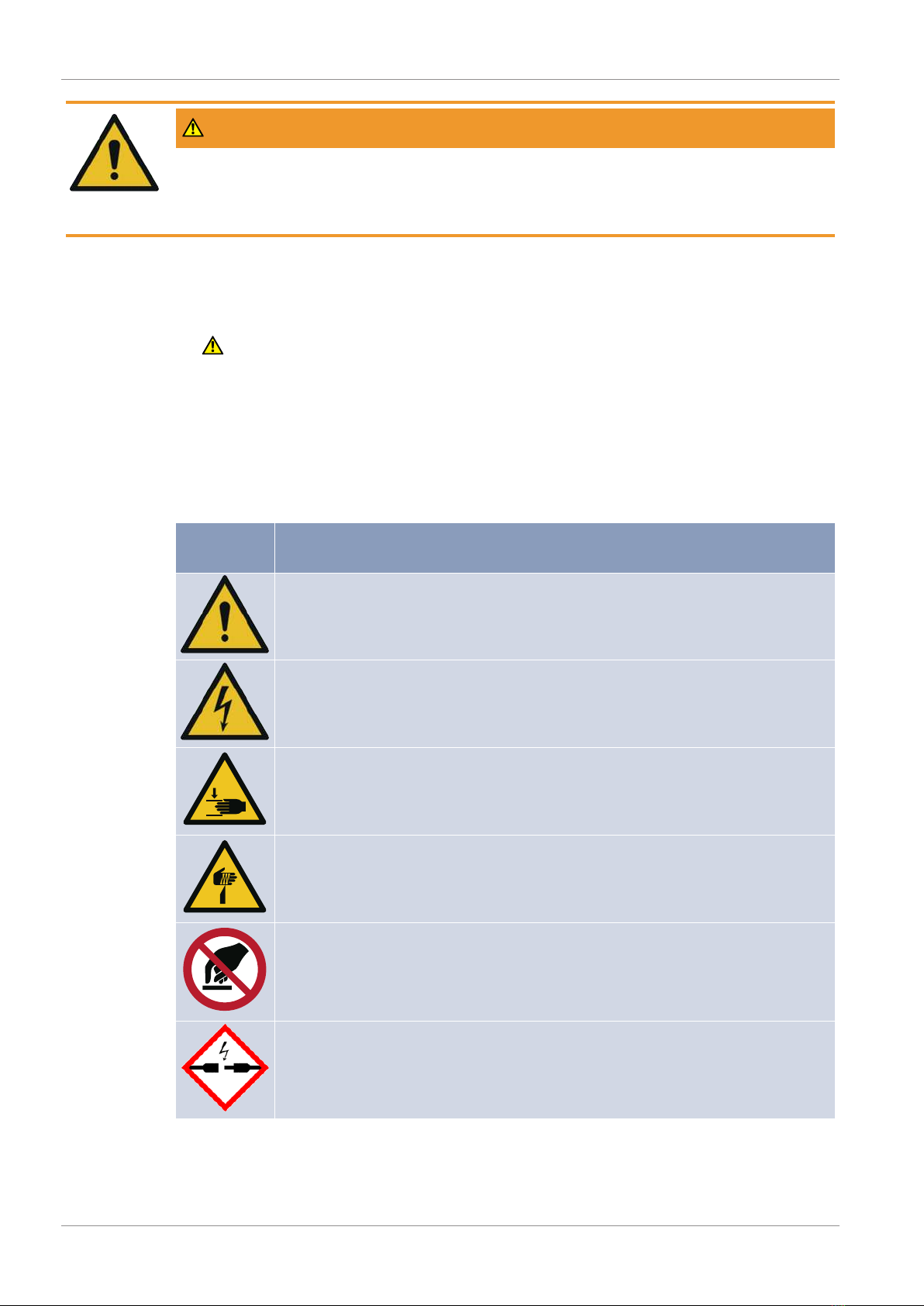
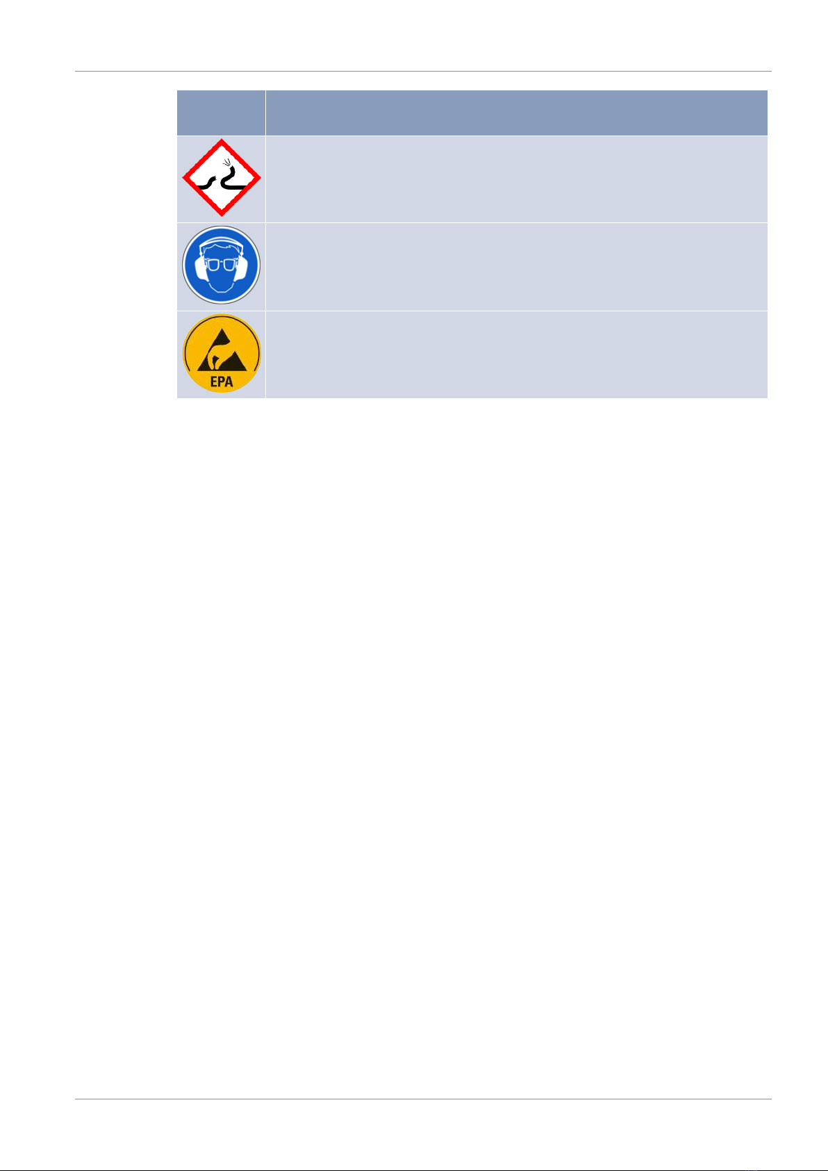
1.5.3 List of Safety Symbols Used........................................................................................... 6
2 General Safety Instructions........................................................................................................8
2.1 Operator's Obligations ............................................................................................................. 8
2.2 Qualification of the Personnel.................................................................................................. 8
2.3 Special Dangers ........................................................................................................................ 9
2.3.1 Dangers from Defective Parts........................................................................................9
2.3.2 Dangers Through the Unauthorized Modification and the Use of Non-OEM Parts ......9
2.3.3 Danger of Electric Shock When Opening the HV Power Supply ....................................9
2.3.4 Dangers from the Pneumatic Equipment ......................................................................9
2.3.5 Risk of Injury Due to Material Transport near the Device ...........................................10
2.3.6 Risk of Injury Due to the Emitters of the Ionisers........................................................10
2.3.7 Danger for Persons with Pacemakers..........................................................................10
2.3.8 Physical Complaints Due to Too Much Ozone.............................................................11
2.3.9 Pain When Touching the Rotating Nozzle in Operation ..............................................11
2.3.10 Hearing Damage Due to Blowing Air Noise .................................................................11
2.3.11 Lubricant Leakage/Contamination ..............................................................................11
2.3.12 Equipment Damage Due to an Electric Arc..................................................................11
2.4 Safety Measures in ESD-Protected Areas............................................................................... 12
3 Product Description ................................................................................................................. 13
3.1 Intended Applications ............................................................................................................ 13
3.2 Ambient and Operating Conditions........................................................................................ 13
3.3 Special Version for ESD Applications...................................................................................... 13
3.4 General View .......................................................................................................................... 14
3.5 Function Principle................................................................................................................... 14
4 Installation ..............................................................................................................................16
4.1 Mechanical Fixing................................................................................................................... 17
4.2 Compressed Air Connection................................................................................................... 18
4.3 Rotation Control (Optional).................................................................................................... 20
4.4 Suction Connection ................................................................................................................ 20
4.5 Electrical Cables and High Voltage Supply.............................................................................. 21
4.5.1 Electrical Cables and High Voltage Supply for AC Ionisers ..........................................21

Table of Contents
TAIFUN-CLEAN 014/015/016 iii
4.5.2 Electrical Cables and High Voltage Supply for DC Ionisers ..........................................22
4.5.3 Earth Connection.........................................................................................................22
5 Start-Up...................................................................................................................................23
6 Troubleshooting ......................................................................................................................25
6.1 Error Display........................................................................................................................... 25
6.1.1 Display of Errors at the AC Ionisers .............................................................................25
6.1.2 Display of Errors at the DC Ionisers .............................................................................25
6.2 Troubleshooting the Ionisation System.................................................................................. 25
6.3 Troubleshooting the Compressed Air Supply......................................................................... 26
6.4 Troubleshooting the Suction System ..................................................................................... 26
6.5 Cleaning Result Is Unsatisfactory ........................................................................................... 26
7 Maintenance ...........................................................................................................................28
7.1 Maintenance Plan .................................................................................................................. 28
7.2 Maintenance of the Rotating Nozzles .................................................................................... 28
7.3 Service for the Rotating Nozzles............................................................................................. 29
7.4 Warranty for the Rotating Nozzles......................................................................................... 30
7.5 Replacing the Rotating Nozzles .............................................................................................. 30
7.6 Replacing the Ionisers ............................................................................................................ 30
7.7 Maintenance of the Ionisers .................................................................................................. 31
7.8 Cleaning the Output Air Component...................................................................................... 31
8 Disposal................................................................................................................................... 32
9 Technical Data .........................................................................................................................33
10 Spare Parts and Accessories..................................................................................................... 34
10.1 Spare Parts ............................................................................................................................. 34
10.2 Accessories ............................................................................................................................. 34
11 Drawings and Order Keys.........................................................................................................36
12 Declaration of Incorporation.................................................................................................... 38

1 | User Instructions
4 TAIFUN-CLEAN 014/015/016
1 User Instructions
1.1 About These Operating Instructions
These operating instructions apply to:
▪ TAIFUN-CLEAN 014 (TC014)
▪ TAIFUN-CLEAN 015 (TC015)
▪ TAIFUN-CLEAN 016 (TC016)
These operating instructions are an integral part of the product and must be available
at any time. Therefore:
uKeep these operating instructions at the product.
uPass these operating instructions on to the next owner if and when you come to
sell the product.
1.2 Applicable Documents
There are separate operating instructions for ionisers and supply units.
1.3 Typographical Conventions
One-step instructions
Instructions consisting of only one action step or instructions in which the order of ac-
tion steps is not important are structured as followed:
üPreconditions (optional).
uStep1 of 1.
ðResult of the action step (optional).
ðResult of the action (optional).
Instructions with several steps
Instructions consisting of action steps in a defined order are structured as followed:
üPreconditions (optional).
1. Step1.
ðResult of the action step (optional).
2. Step2.
ðResult of the action step (optional).
ðResult of the action (optional).
1.4 Abbreviations
In these operating instructions the following abbreviations are used:
▪ AC = Alternating Current
▪ CR = Clean Room
▪ DC = Direct Current
▪ ESD = Electrostatic Discharge

User Instructions | 1
TAIFUN-CLEAN 014/015/016 5
▪ HV = High Voltage
▪ LV = Low Voltage
▪ US = Bottom Side Cleaning
1.5 Explanation of Warning Messages
1.5.1 Description of Hazard Levels
These operating instructions contain notes which you must observe for your personal
safety as well as for avoidance of material damage.
DANGER
An immediate hazard with high risk.
DANGER indicates an imminently hazardous situation which, if not avoided, will result
in death or serious injury.
WARNING
A possible hazard with moderate risk.
WARNING indicates a potentially hazardous situation which, if not avoided, could res-
ult in death or serious injury.
CAUTION
A minor hazard with medium risk.
CAUTION indicates a hazardous situation which, if not avoided, could result in minor or
moderate injury.
NOTICE
Indicates that material damage may result if the appropriate precautions are not
taken.
TIP
Indicates important information about the product or useful tips.
1.5.2 Structure of Warning Messages
Section safety messages
Section safety messages apply to entire chapters or sections of these operating instruc-
tions. Section safety messages are structured as followed:

1 | User Instructions
6 TAIFUN-CLEAN 014/015/016
WARNING
Type and source of danger.
Possible consequences when danger warning is not heeded.
wMeasures to protect against danger.
Embedded safety messages
Embedded safety messages are integrated into the instructions and warn of a danger-
ous step. Embedded safety messages are structured as followed:
1. WARNING!Type and source of danger. Possible consequences when danger
warning is not heeded. Measures to protect against danger.
Step1.
2. Step2.
1.5.3 List of Safety Symbols Used
In these operating instructions the following safety symbols are used:
Safety sym-
bol Meaning
Dangerous area
Dangerous electrical voltage
Danger of crushing
Risk of injury due to sharp parts
Do not touch
Coaxial plugs under high voltage

User Instructions | 1
TAIFUN-CLEAN 014/015/016 7
Safety sym-
bol Meaning
Danger from loose compressed air lines and connectors
Mandatory action: Wear ear and eye protection
ESD-protected areas
Table1: List of safety symbols used

2 | General Safety Instructions
8 TAIFUN-CLEAN 014/015/016
2 General Safety Instructions
2.1 Operator's Obligations
Safety in operational practice can only be assured when all necessary measures are
taken. It is the product operator's responsibility to plan these measures and check
their implementation. In case of wrong operation or misuse, danger exists for life and
limb of the user and danger for the product and other equipment.
In particular the operator must assure that:
▪ the product is used only according to these instructions
▪ the product is operated only in a faultless and fully functional condition
▪ no safety and warning lables are removed and they remain readable
▪ all persons who need to work with or at the product have read and understood
these operating instructions (incl. applicable documents) and that they can refer to
the operating instructions at all times
2.2 Qualification of the Personnel
Type of work/Per-
son Instructed persons
Persons with spe-
cific technical train-
ing
Qualified electri-
cians
Transport X
Set-up X
Electrical installa-
tions X
Pneumatic installa-
tions X
Start-up mechanical
and pneumatic X
Start-up electrical X
Mechanical mainten-
ance, troubleshoot-
ing and repair
X
Electrical mainten-
ance, troubleshoot-
ing and repair
X
Cleaning X
Safety inspection X
Disconnecting the
power supply cables X
Disconnecting the
pneumatic supply
hoses
X
Dismantling X

General Safety Instructions | 2
TAIFUN-CLEAN 014/015/016 9
Type of work/Per-
son Instructed persons
Persons with spe-
cific technical train-
ing
Qualified electri-
cians
Disposal X
Table2: Qualification of the personnel
2.3 Special Dangers
The product is designed safely and corresponds to the state of the art. There is no
danger under normal use. But: During installation and maintenance work there are
dangers, which can only be avoided through the correct handling.
2.3.1 Dangers from Defective Parts
Defective cables and plugs can lead to injury or death by electrical current.
uIn case of visible damage or possible electrical faults, shut down the product imme-
diately.
Defective compressed air lines and connectors can cause severe injury.
uIn case of damage to the compressed air lines and connectors, switch off the com-
pressed air supply immediately and have repairs carried out.
2.3.2 Dangers Through the Unauthorized Modification and the Use of Non-OEM
Parts
The use of unsuitable accessories or unauthorized modifications to the product can
lead to injury.
uDo not make any changes to the product.
uDo not repair the product yourself.
uOnly use accessories that have been approved for the combination with the
product by the manufacturer.
2.3.3 Danger of Electric Shock When Opening the HV Power Supply
There is a danger of electric shock when connecting to the mains and inside the HV
power supply. Touching conductive components can cause death or serious injury.
uOnly a certified electrician may open the HV power supply for purposes of repair.
uBefore opening the HV power supply, turn off the main switch and withdraw the
mains plug or disconnect the power supply cable.
uInstallation and maintenance only when de-energised.
2.3.4 Dangers from the Pneumatic Equipment
Loose compressed air lines and connectors can cause severe injury.
uShut off the compressed air supply during installation and maintenance via the
factory main valve.
Compressed air can move particles into the eyes of user.

2 | General Safety Instructions
10 TAIFUN-CLEAN 014/015/016
uIn applications where pointed and burr-like particles (e.g. iron chips) can occur, al-
ways wear protective glasses.
2.3.5 Risk of Injury Due to Material Transport near the Device
There is a risk of crushing, trapping and injury by shearing with the conveyor (e.g. con-
veyor belt) near the device.
uSafety equipment, e.g. guard plates or ON/OFF switch for immediate shut-down of
the system should be provided by the operator.
uActivate all safety equipment and ON/OFF switch before start-up.
uApproach the device only when the entire system is switched off.
uBefore initial start of the entire system, check that all tools and foreign objects
have been removed.
2.3.6 Risk of Injury Due to the Emitters of the Ionisers
When in operation, the emitters of the ionisers are under high voltage. By means of in-
tegrated HV resistors, the maximum current is limited to about 50–100µA per emitter
tip, depending on the type. The ionisers are thus safe to touch – touching the emitter
tips does not cause bodily injury.
However, high voltage causes a slight tingling sensation. This can lead to startle reac-
tions and therefore result in secondary accidents.
Touching the emitter tips of the DC ionisers during operation can lead to induction of a
charge. The human body can also become electrostatically charged if a person gets too
close to the DC ionisers during operation. Subsequent touching of an earthed compon-
ent can result in an unpleasant and possibly also painful static discharge which also,
however, will not cause injury. This discharge can cause damage to other electronic
components.
uKeep the minimum distance (see Technical Data) from the DC ionisers.
uAvoid touching the emitter tips during operation.
The emitters of the ionisers are sharp. Touching the emitter tips can cause needle-stick
and cut injuries.
uDo not touch the emitter tips even when switched off.
uClean the ionisers only when de-energised.
uDo not restart until the ionisers are dry.
2.3.7 Danger for Persons with Pacemakers
High voltage applied to ioniser generates an alternating electric field (frequency see
Technical Data of the ioniser). This can impair the function of pacemakers. A negative
influence on the proper functioning of pacemakers can lead to ventricular fibrillation
or heart arrest.
uPersons with heart pacemakers must keep a safety distance of 50–100cm (depend-
ing on the model, see the operating instructions for the ioniser) from:
▪ the ioniser discharge tips
▪ HV transformers of the ionisation power supplies if present

General Safety Instructions | 2
TAIFUN-CLEAN 014/015/016 11
uThe operator must mark the danger zone around the ioniser with a warning sign.
2.3.8 Physical Complaints Due to Too Much Ozone
When in operation, the ionisers generate small quantities of ozone. When ozone con-
centration is very high within a long continuous period of exposure, it can cause head-
ache, eye irritation, circulatory problems, etc.
uIn order to avoid exceeding the permitted ozone concentration at the workplace,
the operator must provide sufficient ventilation.
2.3.9 Pain When Touching the Rotating Nozzle in Operation
If the rotating nozzle is installed in the cleaning device in such a way that persons can
come into direct contact with the rotating nozzle when in operation, we recommend
installation of suitable cover discs (see Accessory) as contact protection. Irrespective of
this measure the rotating energy of the rotating nozzle is so low that touching the ro-
tating nozzle could possibly be painful, however no danger of injury exists.
2.3.10 Hearing Damage Due to Blowing Air Noise
Blowing air of compressed air nozzles is resulting in high noise level.
Example: Standard rotating nozzle TCR-7A-070 generates a maximum noise level of
80dBA (laterally, 1m distance) and of 85dBA (in front, 1m distance) at 3.5bar operat-
ing air pressure and barrier-free blowing (without a workpiece).
The value of generated noise level within the application is depending on operating air
pressure, built-in conditions and parts to be cleaned.
Depending on these parameters and the geometry and resonance behaviour of parts,
the resulting noise level can reach values of more than 100dBA. Especially sharp edges
and holes of parts result in high noise levels. Direct decrease of this noise level is diffi-
cult without decline of cleaning result.
uAlways wear hearing protection when the compressed air nozzles are operating.
2.3.11 Lubricant Leakage/Contamination
The bearings of the rotating nozzle are spaced apart from the active compressed air by
internal seals.
The constructive alignment and a corresponding compressed air supply routing
provide effective protection from lubricant leakage from inside the bearing or penetra-
tion of contamination.
In addition the special bearing has a reduced charge amount of lubricant.
Further sealing measures of the bearing chamber prevent loss of lubricant due to leak-
age.
2.3.12 Equipment Damage Due to an Electric Arc
High voltage is applied to coaxial plugs of AC ionisers. When the HV supply is switched
on and coaxial plugs are being plugged in or out, an arc may occur and damage the
socket of the HV supply and the coaxial plug of the AC ioniser.

2 | General Safety Instructions
12 TAIFUN-CLEAN 014/015/016
uPlug in and out coaxial plugs of the AC ionisers only when de-energised.
2.4 Safety Measures in ESD-Protected Areas
Electrostatic discharge can cause defects in customer's electronic components en-
dangered by ESD.
uAssure personal earthing via wrist and shoe earthing.
uWear only clothes which are static dissipative and closed.

Product Description | 3
TAIFUN-CLEAN 014/015/016 13
3 Product Description
3.1 Intended Applications
The non-contact surface cleaning system TAIFUN-CLEAN removes impurities from
three-dimensional as well as structured surfaces.
Loose or electrostatically adhering particles can be cleaned off.
TAIFUN-CLEAN is mounted above, below or next to the product surface to be cleaned.
TAIFUN-CLEAN neutralises electrostatic charges and removes disruptive contamination
by means of compressed air and suction.
3.2 Ambient and Operating Conditions
The product is not suitable for use in areas where danger of explosion exists (EX areas).
Models suitable for this are available.
Ambient temperature must not exceed +50 °C.
The product must not come into contact with dampness, wetness, oil or aggressive
media.
3.3 Special Version for ESD Applications
If the device is designed as ESD version, it is then suitable for cleaning ESD sensitive
components.
As opposed to the non-ESD version, the ESD version of the device incorporates:
▪ ESD compliant hose clamps
▪ Earth terminal bolt
▪ A HV power supply PU55 in "balanced" design should be used to minimise the re-
sidual charge.
NOTICE
Equipment damage due to electrostatic discharge
Electrostatic discharge can cause defects in customer's electronic components en-
dangered by ESD.
wAssure personal earthing via wrist and shoe earthing.
wWear only clothes which are static dissipative and closed.

3 | Product Description
14 TAIFUN-CLEAN 014/015/016
3.4 General View
1
2
43
5
6
Fig.1: Component overview
Item Name Item Name
1 Suction connector 2 Compressed air connection for the
cleaning system
3 Ioniser 4 Ionisation connection
5 Rotation control (optional) 6 Rotating nozzle
3.5 Function Principle
The ioniser (}Fig.2, p.15, item3) generates positive and negative ions which move in
the direction of the work piece surface or material web (}Fig.2, p.15, item4) and on
contact with the surface neutralise disruptive electrostatic charges.
Due to the pulsating airstream from the rotating nozzles (}Fig.2, p.15, item2) in com-
bination with the ionisation, contaminating particles are released from the surface.
The particles are gathered by means of a special suction geometry, transported to the
suction channel (}Fig.2, p.15, item1) and further transported to an external filter
unit.

Product Description | 3
TAIFUN-CLEAN 014/015/016 15
1
2
3
4
3
Fig.2: Function principle
Item Name
1 Suction channel
2 Rotating nozzle
3 Ioniser
4 Object to be cleaned

4 | Installation
16 TAIFUN-CLEAN 014/015/016
4 Installation
uBefore installing the product, inspect it for damage in transit.
WARNING
Risk of injury in case of insufficiently qualified staff
Work performed on the device by unqualified staff may result in personal injury and
equipment damage.
wSet-up, assembly and installation of the device may only be performed by persons
qualified for this while observing the safety instructions.
WARNING
Risk of injury due to electric current
Conductive components can cause serious injury or death.
wDe-energise all components before you begin working.
WARNING
Risk of injury due to loose compressed air lines and connectors
Loose compressed air lines and connectors can cause severe injury.
wBefore starting any work, depressurise all components.
WARNING
Risk of injury due to material transport near the device
There is a risk of crushing, trapping and injury by shearing with the conveyor (e.g. con-
veyor belt) near the device.
wSafety equipment, e.g. guard plates or ON/OFF switch for immediate shut-down of
the system should be provided by the operator.
wActivate all safety equipment and ON/OFF switch before start-up.
wApproach the device only when the entire system is switched off.
wBefore initial start of the entire system, check that all tools and foreign objects
have been removed.

Installation | 4
TAIFUN-CLEAN 014/015/016 17
4.1 Mechanical Fixing
For the screw diameter and maximum permitted torque of the mounting screws refer
to }Table 3, p.17.
The working distance W (}Fig.3, p.17) between the device and the product surface is
shown in }Table 3, p.17.
Model Working distance*
(min. – max.) Mechanical fixing Maximum torque**
TC014 20–40mm Borehole Ø9mm 55Nm
TC015 20–40 mm Slot nuts M8 in T-
slot 15 Nm
TC016 20–40mm Slot nuts M6 in T-
slot 15Nm
Table3: Assembly rated sizes
*The working distance is relative to the object to be cleaned and is measured to the
nearest edge of the cleaning system (without air guide plate).
**The torque must not exceed the maximum permitted torque of the screw.
uTake into account the position of the device in relation to the product conveyor dir-
ection T (}Fig.3, p.17).
T
W
TC016
TC014
TC015
T
W
T
W
Fig.3: Transport direction T and working distance W
The power effect of the blowing air and the suction airstream require, above all in the
case of light weight products, suitable measures for fixing in place and maintenance of
the minimum distance between product surface and the device, e.g. through spacer or
down-holder, product guides and guide rollers to tauten the product.
This also applies to web cleaning applications where the web tension is insufficient to
maintain the working distance.
uAsk your responsible Dr.Escherich sales partner for advice.
Machine components which are earthed must not be located between the ioniser and
the part to be cleaned or in the immediate vicinity of the ionisers.
No additional components must be placed between ionisers and product surface (Ex-
ception: electrically non-conductive or insulated slide or retaining elements if neces-
sary).

4 | Installation
18 TAIFUN-CLEAN 014/015/016
4.2 Compressed Air Connection
Compressed air must be provided via a suitable maintenance unit with filter control
valve and if necessary with water and oil separator to which the compressed air hose
of the product must be connected.
Compressed air quality
The compressed air supply is provided by the customer. The compressed air must com-
ply with the following quality requirements in order to avoid damage to connected
peripheral devices:
▪ technical oil-free
▪ dry
▪ cleaned
▪ maximum residual dust content at least quality class6 (ISO8573-1:2010-04):
particle size 5μm, particle concentration 5mg/m3
Furthermore, depending on the cleaning requirements of the application, the com-
pressed air quality requirements can be considerably higher.
WARNING
Risk of injury due to loose compressed air lines and connectors
Loose compressed air lines and connectors can cause severe injury.
wBefore starting any work, depressurise all components.
TIP
Pressure losses in the compressed air supply line
Compressed air hoses that are too long, undersized cross-sections and constrictions to
the diameter in the compressed air supply line can lead to excessive pressure loss.
wKeep the compressed air hoses as short as practically possible.
wDimension the cross-section of the compressed air line according to the expected
flow rate.
wAvoid constrictions to the diameter in the compressed air supply line:
— no kinks
— no radii less than 3 x the hose diameter
— keep the number of quick-fit connectors as low as possible
}Table 4, p.18 shows the operating air pressure at TAIFUN-CLEAN.
Recommended operating
air pressure [bar]
Maximum permitted oper-
ating air pressure [bar]
Ø compressed air connec-
tion [mm]
1.5–3.5 5.0 See }9Technical Data
[p.33]
Table4: Compressed air connection for the cleaning system
1. The recommended operating pressure is between 1.0 (or 1.5) and 3.5bar. This
pressure range guarantees the rotating speed of the nozzle which was factory ad-
justed.

Installation | 4
TAIFUN-CLEAN 014/015/016 19
2. Exceeding the recommended air pressure of 3.5bar can lead to revs outside of the
specified range and to grease leaking out of the bearing on the nozzle axis.
3. If the operating air pressure is less than recommended, the nozzles rotate too slow
or stop, but won’t be damaged.
4. If the pressure regulator is not located immediately in front of the rotating nozzle,
it may be necessary to set a higher pressure value because of pressure loss in the
feed hose.
NOTICE
Equipment damage due to overpressure
Exceeding the maximum permitted air pressure can lead to damage to the rotating
nozzle. In this case the warranty becomes invalid.
wThe operating air pressure in the rotating nozzle must not exceed the maximum
permitted air pressure.
Compressed air consumption (Nl/min)
1.0 bar 2.0 bar (standard) 3.5 bar
Working width (mm)
Fig.4: Compressed air consumption TC014
Compressed air consumption (Nl/min)
1.0 bar 2.0 bar (standard) 3.5 bar
Working width (mm)
Fig.5: Compressed air consumption TC015

4 | Installation
20 TAIFUN-CLEAN 014/015/016
1.0 bar 2.0 bar (standard) 3.5 bar
Compressed air consumption (Nl/min)
Working width (mm)
Fig.6: Compressed air consumption TC016
4.3 Rotation Control (Optional)
The revs of the rotating nozzles can be monitored by sensors if necessary.
Each rotation of the nozzle produces 2 impulses. These impulses are evaluated via the
TC CONTROL system or an external monitoring system.
The sensor can only be mounted at the factory.
4.4 Suction Connection
The device can be fitted optionally with several suction connectors or alternatively
with suction channel and larger suction connectors.
TIP
Pressure losses in the suction system
Suction hoses that are too long, undersized cross-sections and constrictions to the dia-
meter in the suction system can lead to excessive pressure loss.
wKeep the suction hoses as short as practically possible.
wAvoid constrictions to the diameter in the suction system:
— no kinks
— no radii less than 3 x the hose diameter
1. Attach suction hoses to the suction connectors of TAIFUN-CLEAN (diameters
see }9Technical Data [p.33]) with hose clamps.
These hose clamps are included in the scope of delivery of TAIFUN-CLEAN.
2. Lay suction hoses to the adaptor, to the suction unit or the existing output air sys-
tem.
ESD-protected areas
The conductive suction hose is contacted via the pointed screw of the ESD hose clamp.
The green or green-yellow cable on the hose clamp can be additionally connected to
earth. However, this is not strictly necessary.
This manual suits for next models
2
Table of contents
Other Dr. Escherich Cleaning Equipment manuals
Popular Cleaning Equipment manuals by other brands

Bissell
Bissell CrossWave Cordless 2551 Series Battery removal instructions

Kärcher
Kärcher FR Basic manual

Jetblack Safety
Jetblack Safety JBA-015 Installation operation & maintenance

TEFAL
TEFAL XD5100E0 quick start guide

IPC
IPC PW-H101 2515 NE 3x230v manual

Battenfeld
Battenfeld Frankford Arsenal Quick-N-EZ instructions

SMOKI
SMOKI MAXI 300 Maintenance manual

GreenWorks
GreenWorks SSF405 Operator's manual

SNOWJOE
SNOWJOE SUNJOE SPX-RB1-RM ASSEMBLY QUICK GUIDE

John Downey
John Downey Steamin Demon Classic operating manual

Milwaukee
Milwaukee M12 DRAIN SNAKE Operator's manual

Ultrawave
Ultrawave Hygea 6427 Operator's instruction manual