Pag. 14
Pag. 5
TANKS :
WARNING: when washing the tank or the machine it is mandatory to remove
the ignition key.
To drain the recovery tank use the hose as shown in fig. 3 page 7.
If necessary, the solution tank can also be emptied using the hose as shown in
fig. 3 page7. The same hose, once it has been re-positioned in its seat and with
the tap opened can also serve as a water and solution level indicator.
When the recovery tank reaches its maximum filling level, two sensors stop
the aspirator preventing it from getting damaged by aspirating water.
WARNING: Carefully apply the water disposal procedures when emptying
the tanks.
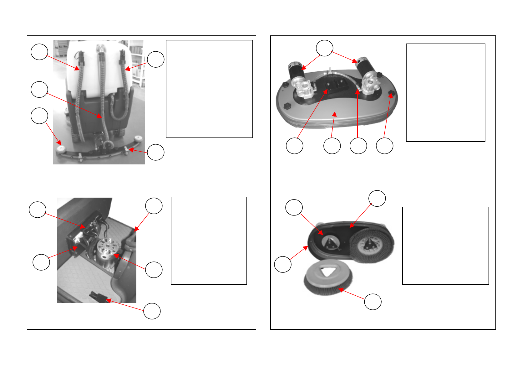
SQUEEGEE :
The squeegee unit inclination can be adjusted using the appropriate knob or
lever ( see fig. 9 page 10).
Best possible drying is ensured if the squeegee is parallel to the floor,
provided that the rubber blades, especially the rear one, are in good
conditions.
WATER FILTER:
In order to ensure water flow to the brushes, it is advisable to periodically
clean the water filter, see fig. 11 page 11.
In this manual the symbol is used to signal possible danger(s).
CAUTION : warns about dangers or potentially dangerous operations that
may cause injuries to the operator.
WARNING : never se flammable products for cleaning but only “suitable
chemical products”.
This machine has been designed and constructed exclusively for the cleaning of indoor
floors in good condition.
GHIBLI warmly advises against other applications.
The information contained in this manual warns about potentially dangerous situations
both for the operator and for the machine.
WARNING : before performing any repairs disconnect the clamp from the
"NEGATIVE" battery wire.
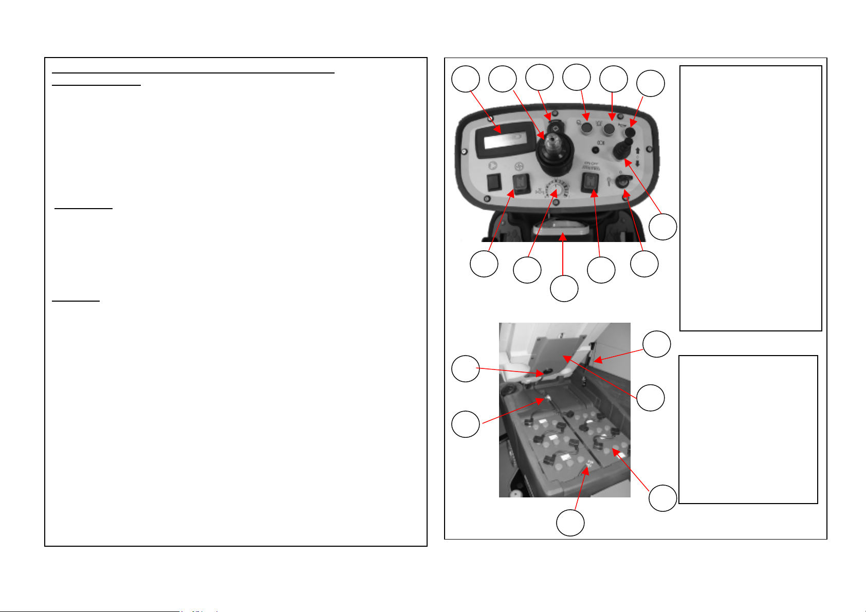
WARNING : if you are not using gel batteries, please remember that
batteries emit dangerous gases and the machine tank must therefore be kept
open while recharging them
WARNING : do not collect flammable materials with the scrubber-dryer
since these can cause explosions or fires.
For Yo r health and safety:
A) Do not use the machine if you have not been instructed about its operation.
- Carefully read the “operation and maintenance” manual before operating the
machine.
- Do not use the machine in areas with flammable or explosive materials.
B) Before starting the machine make sure that all safety devices are working properly.
- Exercise caution when using the machine on sloping or slippery floors.
SAFETY INSTRUCTIONS